About external fire water supply. General information about fire water supply
Chapter 5Operation of funds fire water supply
Operation of fire hydrants.
5.1.1. During the use of a fire hydrant, as well as when checking its technical condition, a fire truck driver and a representative of the operating organization should, as a rule, be at the well.
5.1.2. Opening the cover of the fire hydrant well should be done with a special hook or crowbar, while taking care not to damage the thread of the fire hydrant mounting head.
5.1.3. Fire hydrants are opened and closed by means of a fire column. The fire column is installed by screwing onto the nipple of the hydrant so that the square of its key sits on the square of the hydrant. The outlet pipes of the fire column must be closed with locking devices.
5.1.4. To let water into the hose after installing the fire column, you must:
5.1.4.1. Pre-fill the hydrant with water by opening it half a turn with the central key of the fire column.
5.1.4.2. After filling the hydrant with water, open the central key of the fire column completely by 10-11 turns for old-style fire hydrants and 20-22 turns for new hydrants.
5.1.4.3. Open the gate valves with shut-off valves and trace the passage of water into the pressure hoses connecting the fire column with the fire truck.
5.1.5. To stop the water supply to the hose, proceed in the reverse order:
5.1.5.1. Close the gate valves of the column with shut-off valves.
5.1.5.2. Close the hydrant with the central key of the fire column. After the hydrant is closed, the water from it descends through the drain hole - seed or check valve. If water does not come out of the hydrant through a seed or a check valve, fire departments pump out water from the hydrant riser using a stationary ejector of a fire truck (Appendix 3) and inform the operating organization dispatcher about this to take corrective action.
5.1.6. If there is a hydrant in the well ground water a plug is installed on the drain hole. After using the fire hydrant, it is necessary to pump out water from the well, remove the plug, drain the water from the hydrant riser, and then install the plug on the drain hole.
5.1.7. When opening the cover of the well, it is forbidden to smoke and use open fire to warm the parts in the well. Strictly observe safety measures when checking and during the use of fire hydrants.
When preparing fire hydrants for winter period operating organizations to carry out the following activities:
If there is water in the wells of fire hydrants standing at the level of the flange of the fire stand and above it, pump out water from the well and clog the drain hole (seed) of the hydrant with a wooden plug to prevent water from entering the hydrant riser, which should be recorded in the summary act and logbook fire hydrant checks.
Insulate hatches of hydrant wells with insulation used in construction. Insulation must be laid or applied to the ceiling 0.4 - 0.5 m below the well cover.
IN winter time fire hydrants, sites for the installation of fire trucks, as well as entrances to them must be cleared of snow and ice.
Typical malfunctions of fire hydrants
Symptoms | Causes of the malfunction |
|
The central key of the fire column rotates effortlessly. | Broken worm with ball valve. |
|
The hydrant stem is raised higher than under normal conditions, the fire column is not completely screwed onto the hydrant nipple | Sand got into the worm bushing |
|
The central key of the fire column is turned. | From long-term operation, a square of a fire column key and (or) a square of a fire hydrant stem have been developed |
|
With the central key completely closed, a strong water flow is observed. | The rubber ring of the ball came off. If this defect is found, immediately screw the fire column back on and do not remove it until the arrival of the emergency brigade. |
|
The passage of water due to the lack of tightness at the ball when the hydrant is closed. | Foreign objects have fallen under the rubber ring. |
|
In winter, the central key of the fire column does not rotate. | The ball valve is frozen to the valve box body. Defrost a fire hydrant with steam or with the exhaust gases of fire engine engines. |
Chapter 6Checks of means of fire-fighting water supply
The means of fire-fighting water supply must be constantly monitored to ensure their good condition and constant readiness for use in case of fire.
Checks of fire-fighting water supply are divided into the following types: check without starting water - check No. 1; technical check with water start-up - check No. 2 and check of water pressure networks for water loss. For each type of check in the organization (at the enterprise), a methodology (instruction) must be developed (approved by the head) and agreed with the State Fire Service. During inspections, it is mandatory to control compliance with the regulatory requirements for water sources specified in Section 4 of these Guidelines.
6.1. Inspection No. 1 in settlements and facilities is carried out:
by the engineering and inspection staff of the State Tax Inspectorate when carrying out activities to supervise the implementation of norms and rules fire safety objects (buildings and structures);
the personnel of the guards on duty of the State Fire Service units when extinguishing fires, conducting PTZ, vocational schools, working out plans and fire extinguishing cards, carrying out sentinel service;
service personnel of organizations, enterprises on whose balance sheet there are fire-fighting water supply facilities at least once every two months.
When checking fire hydrants, external inspection
verify :
the presence of signs at the location of the fire hydrant, as well as in the direction of movement towards it;
the presence of a cone (pyramid) on the cover of the fire hydrant well;
the condition of the entrances to the fire hydrant;
the condition of the blind area and the outer cover of the well of underground hydrants, cleaning from dirt, snow and ice;
the internal state of the well of the underground hydrant (at an outdoor temperature of at least -20 ° C);
the presence of a protective cover of the fire hydrant riser;
the presence of insulation of covers (manholes) of fire hydrants.
When checking ground units (ground hydrants), by external inspection, check
the presence of signs at the location of the ground node, as well as in the direction of movement towards it;
condition of entrances to the ground node (ground hydrant);
the presence of a platform for the installation of a fire truck with a length and width of at least 10 m and 3 m, respectively;
the state of shelter of the ground hydrant node;
the presence of fire trunks and hoses at the rate of 40 meters per one branch pipe;
the presence of a button for remote start and stop of water extinguishing pumps;
the presence and serviceability of the connecting heads on the water pipes of ground fire hydrants.
When checking fire reservoirs, external inspection
verify :
the presence of signs at the location of the fire reservoir, as well as in the direction of movement towards it;
condition of entrances to water sources;
the presence of a site for the installation of a fire truck 12x12 m;
the presence of insulation of covers (manholes) and underground reservoirs (in winter);
water level in fire reservoirs, serviceability of the level gauge;
the presence of insulation, the serviceability of water temperature control devices;
serviceability of valves of ground tanks;
the presence and serviceability of connecting heads on the water pipes of fire tanks;
the depth of the reservoir in the place intended for lowering the suction grid.
receiving well (“dry”, “wet”), serviceability of the valve in the well (“dry”), the presence of a grid on the connecting pipeline.
The results of the inspections are recorded in the register of inspections of water sources (Appendix 4). Identified malfunctions are recorded in the register of faulty fire water supply, on the basis of this an act is drawn up on the state of fire water supply sources and one copy is handed over to the head of the enterprise, organization for troubleshooting.
Note:
Fire departments are given the right to control the technical condition of fire hydrants when obligatory observance following conditions:
Checking (testing) hydrants with the launch of water is allowed only at positive outdoor temperatures;
At temperatures from 0 to -20 ° C, only an external inspection of the hydrant is allowed without letting water into the hydrant riser;
Opening the covers of the well at an outdoor temperature below -20 ° C in order to avoid heat loss of the well itself is prohibited;
In all cases, during checks, it is prohibited to use a socket wrench to open the hydrant.
6.2. Check No. 2 with mandatory water release is carried out 2 times a year: in spring (May-June) and in autumn (August-September).
Inspection No. 2 is carried out by a commission appointed by order of the head of enterprises, organizations, institutions, on the balance sheet of which are the means of external fire water supply and consisting of a representative of the administration of this organization and the local division of the State Fire Service.
Check #2 does the following:
6.2.2.1. When checking fire hydrants:
Check the dimensions of the stem square with special overall rings (one with a diameter of 29 mm, the other with a diameter of 31 mm) or by measuring the diagonal of the square, which should be equal to 30 mm;
Check the condition of the hydrant nipple thread;
Check the pressure and flow of water through the hydrant, using one of the following methods;
Close the hydrant, check the operation of the seed hole or valve to release water from the hydrant riser;
Clean the seed hole;
If there is a groundwater hydrant in the well above the fire flange, it is necessary to pump out water from the well, remove the plug, drain the water from the hydrant riser, and then install the plug on the drain hole;
During the spring check, remove the previously clogged seed at the groundwater level in the well below the fire flange;
During the autumn check at the groundwater level above the fire flange, pump out water from the well and the riser of the fire hydrant, clog the seed hole with a wooden plug, about which make an entry in the summary act and in the log book for checking water sources;
6.2.2.2. When checking ground nodes (ground hydrants):
External inspection checks check points No. 1;
Check the operation of the button for remote start and stop of water extinguishing pumps;
Check the pressure and flow of water through the pressure pipes, using one of the following methods;
Check with a tape measure the correspondence of the coordinates on the indicators of hydrants and other water sources;
Check the operation of electric gate valves installed on the bypass lines of water metering devices.
6.2.2.3. When checking fire reservoirs:
External inspection checks check points No. 1;
Check the water yield of fire reservoirs consisting of ground tanks (Appendix 8);
Check the possibility of water intake from the fire reservoir;
Check the compliance of the filling time of fire reservoirs with the requirements of the standards (by calculation, based on the diameter and pressure in the supply pipeline);
When checking fire reservoirs located at the facility, check the presence and serviceability of level gauges and water temperature control devices installed in the control rooms of the duty personnel;
Using a tape measure, check the correspondence of the coordinates on the signs of fire reservoirs.
The results of checks No. 2 are drawn up as a daily act in the form (Appendix 5) and entered in the register of checks of water sources, the identified malfunctions, as a rule, are eliminated during the check. Faulty water sources are entered by the dispatcher of the CPPS (radio telephone operator of the PSCH) into the register of blocked passages and faulty water sources.
Upon completion of inspection No. 2, a summary act is drawn up in the form (Appendix 6) in two copies with the obligatory indication of pumping water from the well and the riser of the fire hydrant and driving fire hydrant seeds in wells with a high level of groundwater and an act of testing fire hydrants (reservoirs) according to the form (Appendix 7) in duplicate with the obligatory indication of water loss.
On the basis of the consolidated GPN, an order is drawn up and handed over to the head of the enterprise, organization for troubleshooting.
6.3. Checking water supply networks for water loss.
It should be borne in mind that water pipelines undergo changes during operation: the network throughput decreases due to pipe corrosion, salt deposits, the withdrawal from the water supply increases, for example, when new consumers are connected to the network, new sections of the network are laid, etc.
Therefore, the actual water yield of network sections in various parts of the city is determined only by special tests of the water supply network on the ground, which are carried out together with workers in the operation of the water supply system annually.
The sections of the water supply network are checked for water loss:
dead-end lines with small pipe diameters;
with reduced pressure;
furthest from pumping stations;
with large water consumption for household, industrial and fire needs;
great length;
old and newly laid.
Devices and methods for measuring water flow. Water flow can be measured in the following ways:
Volume test
This method of measuring water consumption from water supply networks consists in determining the time for filling specially calibrated tanks, as a rule, with a capacity of 500-1000 liters. In this case, the calculation of water consumption is determined using the formula:
Q = V/ t(l/s)
where: V - tank volume, l; t - tank filling time, s.
This method, compared with others, is the most accurate (the error does not exceed ± 1-2%).
2. Test (measurement) with the help of a water meter
The barrel is additionally equipped with a pressure gauge and a set of interchangeable nozzles of various diameters. The flow rate of water from the barrel is determined by the formula for the outflow of liquids from the nozzles:
Or Q=P  , (l/s)
where: H - pressure in the water supply network, m water column;
S is the nozzle resistance;
P - conductivity of the nozzle of the fire barrel.
To determine the conductivity P and S use the following data:
Table 1 |
|||||||||||
Nozzle diameter, mm | |||||||||||
Conductivity nozzle P | |||||||||||
Modern systems water supply systems are complex engineering structures and devices that provide reliable water supply to consumers. Main fire safety requirements provide for the need to receive standard volumes of water under a certain pressure during the estimated time of extinguishing fires. According to their purpose, water pipes are divided into household-drinking production and fire-fighting. Depending on the pressure, fire-fighting water pipes of high and low pressure are distinguished.
Share work on social networks
If this work does not suit you, there is a list of similar works at the bottom of the page. You can also use the search button
Introduction 2.
Types of plumbing. Classification of water supply by pressure 3.
Water supply schemes for settlements 5.
Sources of water supply 8.
Fire hydrant device. requirements for them. nine.
Features of fire water supply in waterless areas 15.
Used literature 22.
Introduction.
Fire water supply is a set of measures to provide water to various consumers to extinguish a fire. The problem of fire water supply is one of the main ones in the field of fire fighting. Modern water supply systems are complex engineering structures and devices that provide reliable water supply to consumers. With the development of water supply to populated areas and industrial enterprises, their fire protection improves, since the design, construction, reconstruction of water pipes takes into account the provision of not only economic, industrial, but also fire-fighting needs. The main fire-fighting requirements provide for the need for the supply of standard volumes of water under a certain pressure during the estimated time of extinguishing fires.
Types of plumbing. Classification of water supply by pressure.
According to their purpose, water pipes are divided into household, industrial and fire-fighting ones. Depending on the pressure, fire-fighting water pipes of high and low pressure are distinguished. In the fire water about water high pressure within 5 minutes after a fire is reported, they create the pressure necessary to extinguish a fire in the highest building without the use of fire engines. To do this, in the buildings of pumping stations or in other departments b fixed premises install stationary fire pumps.
In low pressure water pipesduring a fire, fire pumps are used to create the required pressure, which are connected to fire hydrants using suction hoses.
In high pressure pipelineswater is supplied to the fire site through hose lines directly from hydrants under pressure from stationary fire pumps installed in the pumping station.
All water supply facilities are designed so that during operation they pass estimated flow water for fire needs at the maximum water consumption for domestic and drinking and industrial needs. In addition, in tanks clean water and water towers provide an emergency supply of water to extinguish fires, and fire pumps are installed in the pumping stations of the second lift.
Pump-hose systems,which are collected when extinguishing fires, are also elementary high-pressure fire water pipelines, consisting of a water supply source, a water intake (suction grid), a suction line, a combined pumping station of the first and second rise (fire pump), water pipes (main hose lines), a water supply network ( working hose lines).
water towersdesigned to regulate pressure and flow in the water supply network. They are installed at the beginning, middle and end of the water supply network. The water tower consists of a support (trunk), a tank and a tent-device that protects the tank from cooling and freezing of water in it. The height of the tower is determined hydraulic calculation taking into account the terrain. Usually the height of the tower is 15...40 m.
The capacity of the tank depends on the size of the water supply, its purpose and can vary widely: from a few cubic meters on low-power water pipes to tens of thousands of cubic meters on large urban and industrial water pipes. The size of the control tank is determined depending on the water consumption schedules and the operation of pumping stations. In addition, they include an untouchable fire reserve to extinguish one external and one internal fire within 10 minutes. The tank is equipped with discharge, collapsible, overflow and mud pipes. Often the discharge and collapsible pipes are combined.
A variety of water towers arewater reservoirs,which are designed not only to regulate the pressure and flow in the water supply network, but also to store a fire-fighting supply of water to extinguish fires for 3 hours. The tanks are located on elevated places.
Water tanks and towers are included in the water supply network in series and in parallel. When connected in series, all water from pumping stations passes through them. In this case, the discharge and collapsible pipes are not combined, and they work separately. At a minimum water consumption, excess water is accumulated in a reservoir or in a tank, and at a maximum, this reserve is sent to the water supply network.
When connected in parallel to the water supply network, excess water enters the tanks and tanks (at minimum water consumption), and at maximum water consumption it is sent to the network. In this case, the discharge and distributing pipelines can be combined. To control the water level in tanks and reservoirs, measuring devices are provided.
By type of object servedwater supply systems are divided into city, township, as well as industrial, agricultural, railway, etc.
By type of natural sources usedDistinguish between water pipes that take water from surface sources (rivers, reservoirs, lakes, seas) and underground (artesian, spring). There are also mixed feed water supply systems.
According to the method of water supplywater pipelines are pressure with mechanical water supply by pumps and gravity (gravitational), which are arranged in mountainous areas when the water source is located at a height that provides natural water supply to consumers.
According to the purpose of the systemwater supply is divided intohousehold and drinkingthat meet the needs of the population;production, supplying water technological processes of production;firefighting and combined. The latter suit, as a rule, in settlements. From the same water pipes, water is also supplied to industrial enterprises if they consume an insignificant amount of water or, according to the conditions of the technological process of production, water of drinking quality is required.
With high water consumption, enterprises can have independent water supply systems that provide their household, drinking, industrial and fire-fighting needs. In this case, they usually construct household fire and industrial water pipelines. The combination of fire water supply with economic, and not with production, is explained by the fact that the industrial water supply network is usually less extensive and does not cover all the volumes of the enterprise. In addition, for some technological processes production, water must be supplied under a strictly defined pressure, which will change when extinguishing a fire. And this can lead either to an increase in water consumption, which is not economically feasible, or to an accident in production equipment. An independent fire-fighting water supply system is usually arranged at the most fire hazardous facilities - petrochemical and oil refining enterprises, oil and oil products warehouses, timber exchanges, storage facilities liquefied gases and etc.
Water supply systems can serve both one object, for example, a city or an industrial enterprise, or several objects. In the latter case, these systems are called group systems. If a water supply system serves one building or a small group of compactly located buildings from a nearby source, then it is called local system. To supply water under the required pressure to various parts of the territory of the settlement, which has a significant difference in marks, arrange zoned water supply. A water supply system serving several large water consumers located in a certain area is called a district water supply system.
Water supply schemes for settlements
On the territory of most settlements (cities, towns) there are various categories water users who have different requirements for the quality and quantity of water consumed. In modern urban water pipelines, the consumption of water for the technological needs of industry is on average about 40% of the total volume supplied to the water supply network. Moreover, about 84% of water is taken from surface sources and 16% from underground.
The water supply scheme for cities using surface water sources is shown in the figure. Water enters the water inlet (head) and flows through gravity pipes 2 into the coastal well 3, and from it the pumping station of the first lift (HC-I) 4 is supplied to settling tanks 5 and then to filters 6 for cleaning from pollution and disinfection. After the treatment plant, water enters the reserve tanks
Water supply scheme of the settlement
1 - water intake; 2 - gravity pipes; 3 - coastal well; 4 - pumping station of the 1st lift; 5 - settling tanks; 6 - filters; 7 - spare tanks of clean water; 8 - pumping station II rise; 9 - conduits; 10 - water tower; 11 - main pipelines; 12 - distribution pipelines; 13 - entry into buildings; 14 - clean water consumers 7, of which it is pumped by a pumping station of the second lift (NS-P) 8 through conduits 9 to a pressure-control structure 10 (ground or underground reservoir located on a natural elevation, water tower or hydropneumatic installation). From here, water flows through the main lines 11 and distribution pipes 12 of the water supply network to the inputs to buildings 13 and consumers 14.
A water supply or design system is usually divided into two parts: external and internal. The external water supply includes all facilities for the intake, purification and distribution of water by the water supply network before entering the building. Internal water pipelines are a set of devices that provide water from the external network and supply it to water-folding devices located in the building.
The use of underground water sources usually allows you to do without treatment facilities. Water is supplied directly to reserve tanks 2. When using groundwater, as well as when supplying large cities, there may be not one, but several sources
Plumbing scheme for an underground water source

1 - artesian well with a pump; 2 - spare tank; 3 - NS- II ; 4 - water tower; 5 - water supply network
water supplies located on different sides of the settlement. Such water supply makes it possible to obtain a more uniform distribution of water throughout the network and its flow to consumers. The unevenness of water consumption with an increase in the population in cities is largely smoothed out, which makes it possible to do without pressure-control structures. In this case, water from the NS-P flows directly into the pipes of the water supply network.
Water supply for firefighting purposes in cities is provided by fire trucks from hydrants installed on the water supply network. IN small towns to supply water for extinguishing fires, additional pumps are included in the NS-I, and in major cities fire consumption is an insignificant part of water consumption, therefore, they practically do not affect the mode of operation of the water supply system.
In accordance with modern standards in settlements with a population of up to 500 people, which are located mainly in rural areas, a combined high-pressure water supply system should be installed to provide household, drinking, industrial and fire needs. However, it is not uncommon that only domestic and drinking water supply is constructed, and water is supplied for fire needs by mobile pumps from reservoirs and reservoirs replenished from the water supply.
In small settlements for economic and fire-fighting needs, local water supply systems are most often arranged with water intake from underground sources (mine wells or wells). As water-lifting devices, centrifugal and piston pumps, Airlift systems, wind power plants, etc. The most reliable and convenient in operation centrifugal pumps. As for other water-lifting devices, due to low productivity they can only be used to replenish fire water supplies in reservoirs, reservoirs, water towers.
Sources of water supply
In accordance with the two categories of natural water sources, water intake structures are also divided into two groups: structures for receiving water from surface sources and structures for receiving groundwater. The choice of one or another source of water supply is determined by local natural conditions, sanitary and hygienic requirements for water quality, and technical and economic considerations. Wherever possible, preference should be given to underground sources of water supply.
Surface sources include rivers, lakes and, in some cases, seas. The location of the water intake is determined in such a way that the following conditions are satisfied:
the possibility of using the simplest and cheapest method of taking water from a source;
uninterrupted receipt of the required amount of water;
ensuring the supply of as clean water as possible (cleaning from pollution);
the closest location to the object supplied with water (to reduce the cost of water conduits and water supply).
Groundwater occurs at various depths and in various rocks.
For water supply use:
water of confined aquifers, covered from above with impermeable rocks that protect The groundwater from pollution;
non-pressure groundwater with a free surface, contained in layers that do not have a waterproof roof;
spring (spring) waters, i.e., groundwater that independently comes to the surface of the earth;
mine and mine waters (more often for industrial water supply), i.e., groundwater entering drainage facilities during mining.
Fire hydrant device and operating requirements in winter and summer
A hydrant with a fire column is a water intake device installed on the water supply network and designed to take water when extinguishing a fire.
When extinguishing a fire, a hydrant with a column can be used, firstly, as an external fire hydrant in the case of connecting a fire hose to supply water to a fire extinguishing site and, secondly, as a water feeder for a fire truck pump.
Depending on the design features and conditions of fire protection of protected objects, hydrants are divided into underground and aboveground.
Underground hydrants are installed in special wells, covered with a lid. The fire column is screwed onto the underground hydrant only when it is used. An overhead hydrant is located above the surface of the earth with a column fixed to it.
Fire hydrantis designed to take water from the water supply network to extinguish fires, it consists of a riser, a valve, a valve box, a stem, an adjusting head with a thread and a cover. If the groundwater level is high, a check valve is installed on the outlet of the valve box.

|
1 (10) |
|
|
Rotation frequency of the rod until the valve is fully opened, rpm...... |
12...15 |
|
Effort when opening the hydrant, N (kg).................................................. .............. |
150 (15) |
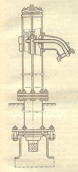
A hydrant-column is installed on the water supply network using a fire stand without a well device. Bandwidth combined hydrant 20 l/s.
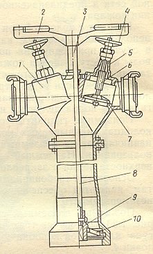
Fire columnIt is used to open and close a fire hydrant, as well as to connect fire hoses when taking water from the water supply network to extinguish fires. The main parts of the column are the body and the head. In the lower part of the body there is a threaded ring for connecting the column to a fire hydrant. In the upper part there is a column control and two branch pipes with connecting heads and two valves. A central key (tubular rod) with a square coupling at the bottom and a handle at the top passes through the gland in the head of the column. The handle is rotated with the valves of the discharge pipes closed. With the valves open, the handwheels will fall into the field of rotation of the handle. Thus, the column has a lock that excludes the rotation of the central key when the valves of the discharge pipes are open. Remove the column from the hydrant only when the hydrant valve is closed.
Technical specifications underground fire hydrant
|
Nominal passage, mm ............................................... ...................................... |
|
|
Working pressure, MPa (kgf/cm 2 ) ................................................................. |
0,8 (8) |
|
Nominal passage of the connecting head, mm .............................................. |
|
|
Weight, kg, not more than ............................................... ............................................ |
Requirements for the operation of fire hydrants in winter and summer
There are mandatory rules for the operation of fire hydrants. Improper handling of fire hydrants can lead to an accident on the water supply network, disruption of the water supply and accidents.
Preparation of fire water supply for operation in winter conditions carried out:
urban water supply - during the period of the autumn inspection by the mobile teams of the AVR REVS (departments);
object water supply - during the autumn inspection by the water supply services of the objects.
Preparation of fire water supply for operation in winter conditions includes:
pumping out water from the risers of fire hydrants of the Moscow type and sealing drain holes with wooden plugs;
with steady sub-zero temperature outside air, pumping out water from the wells of hydrants filled above the level of the riser, followed by the execution of clause 1;
fire hydrants subject to flooding with groundwater and melt water are taken to a special account (Appendix No. 1 "Instructions ...") by the linear sections of the REVS and district fire departments with a mandatory mark in the book of fire water supply checks, subsequent monitoring of their condition by the REVS, pumping water from risers after thaws (if necessary) and mandatory transmission of information to district fire departments;
filling wells of hydrants with a special heat-insulating filler.
Requirements for the commissioning of new sources of fire water supply.
To the fire hydrants
Fire hydrants should be installed on ring water supply networks. It is allowed to install fire hydrants on dead-end lines, regardless of the water consumption for fire extinguishing, provided that their length does not exceed 200 meters.
The diameter of the water pipes on which fire hydrants are installed is determined by calculation in accordance with clause 8.46 of SNiP 2.04.02-84 "Water supply. External networks and structures", but the minimum diameter of water pipes in settlements and on industrial enterprises must be at least 100 mm, in rural settlements - at least 75 mm, the maximum pipe diameter must not exceed 500 mm.
Fire hydrants should be located along highways at a distance of no more than 2.5 m from the edge of the carriageway, but no closer than 5 m from the walls of buildings. It is allowed to have hydrants on the roadway. In the historical part of the city it is allowed to place fire hydrants in accordance with the requirements of clause 8.55 of VSN-89. The distance between hydrants should not exceed 150 meters.
Around the hatches of wells located in the built-up areas of off-road coatings or in the green zone, blind areas 1 m wide with a slope from the hatches should be provided, the blind areas should be 0.05 m higher than the adjacent territory; on the carriageway of streets with improved capital coverings manhole covers must be flush with the surface of the roadway; well hatches on water conduits laid in an undeveloped area should be 0.2 m above the ground.
There must be a free entrance to the hydrant with a width of at least 3.5 meters.
At the location of the fire hydrant, an index plate should be installed at a height of 2-2.5 m from the ground (plates on objects made in accordance with GOST 12.4.026-76 "Signal colors and safety signs" are installed directly at water sources and in the direction of movement to him). The plate should be 12x16 cm in size, red and have inscriptions white color indicating:
type of hydrant (Moscow-type hydrant is denoted by the letter M);
diameter of the water supply network in millimeters (inches);
the nature of the water supply network (a dead-end network is indicated by the letter T in the left upper corner plates);
fire hydrant number (should correspond to the number of the house on which the coordination plate is located). Recording numbers with the number "0" in front (01.02.03., etc.) means that the index plates of these fire hydrants are located on trees, metal poles or street lighting poles, without reference to house numbers;
digital value of the distance in meters from the plate to the hydrant.
In accordance with clause 1.12. GOST 12.4.009-83 fire hydrant indicators must be illuminated by lamps or made using fluorescent or reflective coatings
Hydrants in wells are installed vertically. The axis of the installed hydrant should be located no closer than 175 mm and no further than 200 mm horizontally from the wall of the hatch neck. The distance from the top of the hydrant to the top edge of the hatch should be no more than 400 mm and no less than 150 mm. The technical condition of the fire hydrant is checked by installing a column with a mandatory start-up of water, and there should be no leakage of water in the flange connections of the hydrant.
After the commissioning of fire hydrants, an act is drawn up in 4 copies (one copy each for the fire department, fire department, REVS (department) and the organization that carried out the construction and installation work).
When accepting into operation hydrants located on the facility water supply networks, it is required to additionally test the network for water loss. After the commissioning of fire hydrants at the facility, an act of any form is drawn up in 4 copies (one for the district fire department, the second for the customer, the third for the general contractor, the fourth for the DSPT). On the basis of the act, the characteristics of the fire-fighting water supply of the object are entered into summary sheet object water supply.
To gravity wells
To take water from natural water sources with swampy banks or the impossibility of direct water intake from them, gravity (receiving) wells are arranged for fire extinguishing purposes.
Gravity wells must have dimensions in terms of at least 0.8x0.8 m. They can be made of concrete, stone and wood. The well must be equipped with two covers, the space between which is filled with insulating material for the winter period, which protects the water from freezing.
The depth of water in the well must be at least 1.5 m. The well is connected to the water source by a supply pipe, the diameter of which must be at least 200 mm. The end of the pipe going into the water source must be located above the bottom by at least 0.5 m and below the horizon low waters, not less than 1.0 m. At the end of the pipe from the side of the water source, a mesh of metal wire, which prevents fish and various objects from being sucked into the pipe.
There should be a free access to the gravity well, designed for the simultaneous installation of two fire trucks. At the location of the gravity well, a light or fluorescent sign with the inscription "CKN" should be installed.
To fire ponds
The need for a device and the required volume of fire-fighting reservoirs for the objects and settlements specified in note 1, clause 2.11. should be determined according to the water consumption rates for the estimated fire extinguishing time in accordance with the instructions of paragraphs 2.13.-2.17. and 2.24. SNiP 2.04.02-84.
The number of fire reservoirs must be at least two, while each reservoir must store half the volume of water for fire extinguishing (clause 9.29. SNiP 2.04.02-84).
Fire reservoirs should be placed from the condition of their service to buildings located within a radius of:
In the presence of autopumps - 200 m;
In the presence of motor pumps - 100-150 m, depending on the type of motor pump (clause 9.30. SNiP 2.04.02-84).
Distance from reservoirs to buildings of 3,4 and 5 degrees of fire resistance and up to open warehouses combustible materials must be at least 30 m, to buildings of 1 and 2 degrees of fire resistance - at least 10 m (clause 9.30. SNiP 2.04.02-84).
If the direct intake of water from a fire reservoir by car pumps or motor pumps is difficult, it is necessary to provide for receiving wells with a volume of 3-5 cubic meters. meters. The diameter of the connecting pipeline should be taken from the condition of skipping the estimated water flow for external fire extinguishing, but not less than 200 mm. In front of the receiving well on the connecting pipeline, a well with a valve should be installed, the steering wheel of which must be brought out under the hatch cover. A grid should be provided on the connecting pipeline from the side of the reservoir.
Water must be drawn from each reservoir by at least two fire pumps, preferably from different sides.
Entrances with platforms for turning fire trucks, no less than 12x12 m in size, are arranged to fire reservoirs and receiving wells.
At the location of the fire reservoir, a light or fluorescent indicator should be installed with the following: the letter index PV, the digital values of the water supply in a cubic meter. meters and the number of fire trucks that can be simultaneously installed on the site near the reservoir.
For reliable water intake from natural reservoirs with a high steepness of the slopes of the coast, as well as a significant seasonal fluctuation in water horizons, entrances (piers) are arranged that can withstand the load of fire trucks. The entrance (pier) area should be located no higher than 5 m from the level of the low water horizon (LWL) and above the high water horizon (HWL) by at least 0.7 m and equipped with a drain tray for suction hoses. The depth of water, taking into account freezing in winter, should be at least 1 m, otherwise, a foundation pit (pit) is arranged at the site of the fence. The width of the platform flooring should be at least 4.5-5 m with a slope towards the coast and have a strong side fence 0.7-0.8 m high. less than 25x25 cm.
The chiefs (deputy chiefs) of the units should leave for the technical acceptance of new or reconstructed sources of fire-fighting water supply.
Features of fire water supply in waterless areas
Sometimes, due to the underdeveloped system of urban water supply, there is not enough water for fire extinguishing. In these cases, the head of the first unit that arrived at the fire fire brigade should: organize the supply of fire trunks in decisive directions, ensuring extinguishing in other areas of the fire by dismantling structures and creating the necessary gaps; take measures to find out the location of the nearest water sources from which additional water can be obtained by installing fire fighting equipment for work in pumping or to give a ride with tank trucks, fuel trucks, watering machines and other equipment. When extinguishing a fire by transporting water, such a number of trunks should be used, the uninterrupted operation of which would be ensured by the transported water.
Identification of urban areas not provided with water for fire extinguishing
The determination of building sites that are not provided with water for extinguishing in the area of \u200b\u200bthe departure of the fire department should be preceded by work to determine the water loss of the water supply network for fire extinguishing in strict accordance with regulatory requirements set out in SNiP. When analyzing water loss to extinguish fires in water supply networks, it is necessary to carefully identify areas that do not have water supply networks, pre-built reservoirs (reservoirs), as well as natural water sources (rivers, lakes, ponds, etc.). This information should be put on the water source chart and plots (areas) raised with the necessary calculations, schemes for obtaining water (by transportation, pumping) in case of extinguishing fires on them.
Organization of water supply to the place of fire in waterless areas
The conditions for successful fire extinguishing require a constant supply of the required calculated amount of water to the fire site. Practitioners of the fire department are well aware of the importance of obtaining water in a timely manner and in the required quantity to extinguish fires, which in most cases is the main means of fighting fire.
In each fire department garrison, in the area served by the fire department, based on the analysis of the availability of water for fire fighting, organizational and practical measures should be developed to ensure the organization of timely and in the required amount of water supply for extinguishing fires.
With a lack of water, it is very important to take timely measures to deliver it from the nearest water sources, using regular fire equipment, as well as equipment National economy. In waterless areas, one should not neglect such sources of water as reservoirs with a water level below the suction height of fire equipment or the absence of reliable access roads to them. In these cases, it is necessary to organize the intake of water and its supply using hydraulic elevators, water-removing ejectors and motor pumps. One of the ways to get a large number water through existing water pipelines that have insufficient pressure and minimum flow is to turn on additional backup booster pumps, and in more complex fires, turn off individual sections of the water supply network to direct additional water to the fire site.
When organizing the supply of water by tankers, it must be borne in mind that from a clear and organized work Tanker trucks depend on the uninterrupted operation of the first delivered trunk in the main direction of the spread of fire, and even more so the further introduction of additional trunks to localize and eliminate the fire. To reduce the time when refueling tankers with water and emptying them at the fire site, it is necessary to organize a tanker refueling point at the water source, and a water consumption point at the fire site.
It is advisable to install auto pumps, motor pumps at the point of filling tankers; at the point of water consumption - tank trucks into which water is drained to ensure permanent job fire hoses.
Use of jet pumps to draw and supply water to the fire site
To take water from natural water sources that have unfavorable conditions for the access of fire trucks to them (steep or swampy banks), you can use jet pumps - hydraulic elevators and water-removing ejectors. The operation of these pumps is based on the principle of ejection, created by the energy of the working medium. working environment for hydraulic elevators and ejectors, it is water supplied from pumps of fire trucks or fire motor pumps.
As the practice of extinguishing fires in areas with underdeveloped water supply shows, in the absence of access roads to sources of natural water supply or with unsatisfactory terrain, hydraulic elevators can be used to take water from open water sources at a lifting height of up to 20 m, located at a distance of up to 100 m with a water layer thickness at least 5 cm.
At present, hydraulic elevators G-600 are widely used, water-removing ejectors EV-200, which have the same purpose as G-600, are less commonly used.
The G-600 hydraulic elevator consists of a vacuum chamber and a suction grate; with the help of bolts, an elbow and a diffuser with a mixing chamber and a stand are attached to the vacuum chamber. The conical nozzle is screwed onto the elbow fitting and placed inside the vacuum chamber. To connect the pressure hoses to the hydraulic elevator, there are coupling heads at the ends of the diffuser and the elbow.
The principle of operation of the hydraulic elevator is as follows: under the pressure created by the pump, water flows to the hydraulic elevator. A jet of water emerging from the nozzle creates a vacuum in the diffuser. Under the influence of atmospheric pressure on the surface of the reservoir, water from it through the grate rushes into vacuum chamber, then into the diffuser, where it mixes with water supplied to the hydraulic elevator.
In the practice of extinguishing fires with the adaptation of hydraulic elevators, the following schemes are most widely used.
1. Scheme of water intake by hydraulic elevator systems using suction hoses. The operation of this scheme is carried out when it is necessary to obtain significant water consumption to extinguish a fire. Water is taken from the tank truck through the suction hose by the pump, and its working part is fed through the pressure pipe and further along the pressure fire hose to the hydraulic elevator, from which, together with the ejected water, it enters the tank through the return line of the fire hoses. The ejected part of the water obtained in this way is directed through the second nozzle of the pump to extinguish the fire.
2. Scheme of water intake by hydroelevator systems using a stationary pipeline. In this case, water from the tank truck is supplied through a pipeline connecting the tank with the suction cavity of the pump. In this case, the capacity of the tank truck plays the role of an intermediate capacity that ensures the stable operation of the hydraulic elevator system.
3. Scheme of water intake by hydraulic elevator systems using a water collector. The water collector is installed on the suction pipe of the pump, and the capacity of the tanker is used only to start the system. After starting, the container is turned off and does not participate in the operation of the system. Working and ejected water enters directly into the pump.
When supplying water to the fire site, it is necessary to maintain pressure on the pump, which depends on the ejected flow rate and the height of the water rise from the source. The pressure value when working with the G-600 hydraulic elevator is taken according to the table.
|
Water lifting height, m |
Pump pressure |
||
|
One barrel A or three barrels B |
Two barrels B |
One barrel B |
|
To determine the possibility of bringing the hydraulic elevator system into operation, the water supply in the tanker tank is compared ( V ,l) with the amount of water needed to start it. This quantity is determined by the formula
where - respectively, the volumes of water in the inlet and outlet hose lines, l, determined by the formula ( l – length of the hose line of the system, m; 2 – water reserve coefficient (for one hydroelevator system)).
or according to the table
|
Number of hydraulic elevators |
Hose line diameter, mm |
Length of hose lines, m |
||||
|
One EV-200 |
1100 |
|||||
|
Two EV-200 |
1040 |
1300 |
||||
|
Two EV-200 |
1170 |
1320 1560 |
1650 1950 |
|||
|
Three EV-200 |
1044 |
1287 1566 |
1716 2088 |
2145 2610 |
||
|
One G-600 |
1096 |
1370 |
||||
If the amount of water in the tank remains less than necessary, it must be replenished to the required amount. During normal operation of the hydraulic elevator, it is capable of supplying at least 600 l/min of water, which is sufficient for the operation of one barrel with a 19 mm diameter shower or two or three barrels with a 13 mm diameter shower. The uninterrupted operation of the hydraulic elevator of the system requires all personnel to constantly monitor the correct operation of all sections of the system and take urgent measures to eliminate the detected malfunctions.
Below are the most common malfunctions that can lead to a system shutdown and how to resolve them.
|
Faults |
Troubleshooting |
|
Not enough water in the tank Clogged hydraulic lift nozzle The suction grill is clogged The suction grate of the hydraulic elevator is not immersed in the reservoir Hose lines approaching the hydraulic elevator and departing from it have creases Sudden drop in engine speed Flattening of the sleeves of the hydraulic elevator system Clogging of hydraulic elevators Exceeding the maximum suction height or distance from the installation site of the autopump to the water source Gust of sleeves in the hydraulic elevator system |
Fill up to required amount Disassemble and clean the nozzle clean grate Submerge the grate in a pond Adjust sleeves to eliminate creases Maintain the desired engine operating mode, excluding speed reduction Same Clean the hydraulic elevator from foreign objects Prior to the deployment of the hydraulic elevator system, it is necessary to determine the maximum distance from the installation site of the autopump to the water source and the suction height Damaged sleeves must be replaced with serviceable ones or repaired by applying clamps |
Water supply to the fire site by pumpingIt is used mainly at a significant distance from the water sources of the fire object. This is due to the fact that one pump installed on the water source is not able to create enough pressure to overcome pressure losses in the hose lines and to create working jets of fire nozzles directly at the fire site. For this reason, a pumping method is used, which consists in the fact that water from the water source to the fire site is sequentially supplied from one auto-pump to the next, and the latter in the pumping scheme supplies water directly through the working lines to extinguish the fire.
The practice of using this method of transporting water to supply it to the fire site is quite well developed and, with the clear action of fire truck crews, ensures successful extinguishing of fires that occur in areas with insufficiently developed water supply.
LIST OF USED LITERATURE
1. Abramov N.N. Water supply: Textbook for universities - 2nd ed., Revised. and additional - M .: Stroyizdat, 1988. — 480 s.
2. Beletsky B.F. Designs of water supply and sewerage facilities - M .: Stroyizdat, 1989. -447 p.
3. Kalitsun V.I. Hydraulics, water supply and sewerage: Tutorial for universities / V.I.Kalitsun, V.S. Kedrov, Yu.M. Laskov - 4th ed. revised and additional – M.: Stroyizdat, 2002. – 398 p.
4. Prozorov I.V. Hydraulics, water supply and sewerage: Textbook for building. special universities /I.V. Prozorov, G.I. Nikoladze, A.V. Minaev. – M.: high school, 1995. -448 p.
Other related works that may interest you.vshm> |
|||
| 12257. | Water supply of the city of Kasby | 36.69KB | |
| The purpose of the thesis project and the tasks to be solved: Determining the area of blocks located in the city and the population Determining the daily water consumption Determining the hourly water consumption Tracing water conduits in the network Hydraulic calculation of the network Determination of free pressures Calculation of the longitudinal profile of the main water supply collector Selection of structures in the network Inverter crossing the river water pumping station wells. Daily water consumption... | |||
| 12258. | Water supply of the city of Pakhtakor | 36.83KB | |
| Hydrography The amount of water is the rate of flow of water. The main types of water consumption. Determination of the estimated daily water consumption of the water consumption rate for household drinking needs of the population and landscaping .... | |||
| 15533. | Water supply of the intra-quarter network | 472.08KB | |
| List of permissive and executive documentation. formed during the performance of work at the facility. Organization and technology of work in the main period. Loading and unloading materials storage. Geodetic works. | |||
| 13791. | Water supply and sanitation. Outdoor networks and facilities | 23.08MB | |
| The reference book systematizes materials on the calculation, design, design of networks and structures, optimization of external water supply and sanitation systems, water and sewer pumping stations, etc. related to security issues environment and the ecology of populated areas ... | |||
Fire water supply systems are systems in which water must meet several important criteria: be available at any time of the day and year and be in sufficient quantity to extinguish the fire. Both criteria are extremely important, because the result of extinguishing a fire directly depends on them, which means that human lives are at stake or, in best case, property.
Types and classification
For convenience, we present the data in the form of a table:
The factors by which this classification of types of water supply is carried out directly affect the result when extinguishing a fire.
Natural and artificial water supply
By natural water supply is meant access to a source of water, the origin of which did not depend on man. It can be any body of water: a river, lake, reservoir, pond or sea. The human factor in this case plays a significant role in organizing the access to such a source of water supply. Access should be free and organized by a place for water intake. At first glance, this may seem like a trifle, but such an attitude is a delusion.
The natural source at the place of water intake must have sufficient depth, the bottom, which must be clean. In this case, much depends on natural factors, however, human intervention takes place for quality water intake. Over the years, it may happen that the water source has dried up completely or the water level has dropped significantly. In this case, you should look for a new source of water supply and not necessarily of natural origin. Do not neglect searches.
Artificial water supply is represented by water pipes and fire tank systems. If the construction of the house and the supply of fire water supply to it was carried out according to certain rules and standards, it fully complies with all necessary provisions.
According to building codes and regulations, a fire water supply system must be:
- at residential buildings, whose height ranges from 12 floors;
- in administrative buildings of 6 floors and above;
- in all dormitories and public buildings without exception, regardless of their number of storeys;
- at administrative buildings of an industrial orientation, which have a volume of 5000 cubic meters or more;
- at conference halls, cinemas, clubs, assembly halls which are equipped with cinematographic equipment;
- practically at all, without exception, industrial and warehouse premises.
External and internal water supply
From the name it becomes clear where the source of fire extinguishing water is located. It remains only to find out which water supply is more efficient in this case. Practice shows that for better fire extinguishing and minimization of the consequences of a fire, both types will prove themselves properly. However, there are small nuances. Large in volume, and, accordingly, in number of storeys, the building should be represented by both types of water supply. An exception can only be small buildings that have a small number of storeys and / or a small volume.

Internal water supply is represented by PC - fire hydrants. They should be placed in easily accessible places. Usually these are corridor exits, lobbies, staircase landings, provided that they are heated, in the corridors themselves, if their length exceeds 20 meters. Regulations the same length of the fire hose inside the PC is provided, and the same diameter of the valve and lock of the fire hose.
High and low pressure water supply
Low-pressure water pipelines must supply water with a jet with a water outlet of at least 2.5 l / s and a jet of at least 10 meters. High pressure water supply has more complex system: no later than 5 minutes after a fire message has been received, the pumps that create required pressure in the system for effective water pressure.
The choice of what will be the fire water supply - with high or low pressure - depends on the design of the building. Below is a table that will help you understand the state of fire water pipelines in terms of the flow of water needed for fire extinguishing:
| Jet or room height, m | Jet volume, l/s | Head, sleeve length, m | Jet volume, l/s | Head, sleeve length, m | Jet volume, l/s | Head, sleeve length, m | ||||||
| 10 | 15 | 20 | 10 | 15 | 20 | 10 | 15 | 20 | ||||
| Tip spray diameter, mm | ||||||||||||
| 13 | 16 | 19 | ||||||||||
| Fire hydrants with a diameter of 50 mm | ||||||||||||
| 6 | - | - | - | - | 2.4 | 9.4 | 9.8 | 10.2 | 3.4 | 8.4 | 9.5 | 10.3 |
| 8 | - | - | - | - | 2.6 | 13.3 | 13.7 | 14.1 | 4.2 | 12.0 | 13.2 | 14.5 |
| 10 | - | - | - | - | 3.4 | 15.2 | 15.7 | 16.3 | 4.6 | 16.0 | 17.4 | 18.2 |
| 12 | 2.4 | 20.3 | 20.6 | 21.3 | 3.8 | 18.8 | 19.3 | 21.3 | 5.3 | 20.4 | 22.4 | 24.8 |
| 14 | 2.6 | 23.5 | 24.7 | 24.9 | 4.2 | 24.1 | 25.4 | 26.2 | - | - | - | - |
| 16 | 3.3 | 31.7 | 32.4 | 32.8 | 4.8 | 29.3 | 30.2 | 31.5 | - | - | - | - |
| 18 | 3.5 | 39.4 | 39.7 | 40.2 | 5.2 | 37 | 38 | 40 | - | - | - | - |
| Fire hydrants with a diameter of 65 mm | ||||||||||||
| 6 | - | - | - | - | 2.5 | 8.6 | 8.9 | 9.2 | 3.2 | 7.4 | 8.2 | 8.7 |
| 8 | - | - | - | - | 2.7 | 11.2 | 11.6 | 11.9 | 4.4 | 11.3 | 11.8 | 12.3 |
| 10 | - | - | - | - | 3.2 | 14.3 | 14.5 | 14.8 | 4.7 | 14.3 | 14.8 | 15.1 |
| 12 | 2.4 | 19.7 | 19.9 | 20.2 | 3.6 | 18.2 | 18.5 | 18.9 | 5.3 | 18.3 | 18.6 | 19.3 |
| 14 | 2.7 | 23.2 | 23.6 | 23.8 | 4.3 | 23.3 | 23.7 | 23.9 | 5.6 | 21.4 | 22.2 | 23.0 |
| 16 | 3.0 | 30.0 | 31.4 | 31.7 | 4.7 | 27.4 | 28.4 | 28.8 | 6.2 | 26.0 | 27.4 | 28.4 |
| 18 | 3.5 | 37 | 38.2 | 38.6 | 5.0 | 33.3 | 34.5 | 34.8 | 6.9 | 32.5 | 33.6 | 34.2 |
| 20 | 3.8 | 46.4 | 46.8 | 47.2 | 5.5 | 41.3 | 41.6 | 42.5 | 7.4 | 37.3 | 38.7 | 39.2 |
water towers
Separately, we should consider water towers - a kind of water tanks designed to extinguish fires. By themselves, water towers regulate the pressure, as well as the flow of water in the water supply network. According to SNiP, their installation is carried out in such a way that they start and end the water supply network. Any water tower consists of a support-barrel and a reservoir. To prevent freezing of water in it, the water tower must be protected by a tent.

Otherwise, when negative temperatures freezing water will expand the walls of the tank or support, causing water to leak. The height of water towers depends on the terrain and usually ranges from 10 to 45 meters. The volume of the tower also changes accordingly: from a few cubic meters to tens of thousands of cubic meters of water.
One of the varieties of water towers are water tanks. Their goal: to store such an amount of water that would be sufficient to effectively extinguish a specific object for a duration of at least 2.5 hours.
Both water towers and water tanks are equipped with special measuring instruments to control the water level.
fire hydrants
A hydrant is a device for taking water when extinguishing fires. Depending on the location, fire hydrants can be used either to connect a fire hose or to supply water to a fire truck.
Distinguish between underground and aboveground hydrants. An underground hydrant must be located below ground level in a specially equipped manhole cover, but at the same time have free access to it. That is, it should not be closed by anything, and nothing should prevent the connection of the fire hose. An overhead hydrant is installed above ground level and is a column with an adjusting head. On the head there is a thread or a special lock for quick attachment of a fire hose.
Pumping stations
For forced distillation of water through the system and to create the necessary pressure and pressure, there are pumping stations - also one of the components of the entire water supply system in case of fires.
Typically, a pumping station is a room in which pumps are placed (their number depends on the water supply system), power supply systems and pipelines that set the direction from the pumping station.

The pumps are equipped with pressure gauges (to measure the pressure that the pump creates) and pressure and vacuum meters (measure the vacuum when water is taken). The location of pumps, pipelines, electrical panels and other structures at the pumping station should be such that they do not interfere with free access to them, ensure normal functioning, and also expand the area of the pumping station in the future.
The scheme of operation of the pumping station should be built in such a way that, in the event of a fire, it is possible to respond immediately. The second feature of each pumping station is the ability to take in water intended for household needs. This allows you to cope with a fire if there is a shortage of water in the fire system.
Typically, pumping stations are organized either in basements buildings, or independently of them. Since the pumping stations are powered from a high voltage network, much attention is paid to safety when working at the station, as well as during emergencies. Water and electricity combined are not exactly good friends for a person.
Alarm and automatic operation of the water supply
Human factor at work fire fighting system, as practice shows, is not reliable enough. Automation that has been properly tested and confirmed normative documents, is more reliable and such. Which can ensure the necessary uninterrupted operation of any of the elements of the system. Water flow, pressure control, temperature regime, voltage control in electrical system power supply, various kinds of protection, as well as a warning system - all this should be done automatically.

Composition of the fire cabinet kit
Alarm signaling is used to provide light and / or sound notification of a fire, the start of operation of one of the elements of the fire system, breakdowns during the operation of the system. Signals should be sent to a fire station or to another place where there is a 24-hour service staff. Wherein sound signals have differences in their tone, depending on what the duty officer needs to be warned about.
Conclusion
Over the many years of firefighting practice, it has been repeatedly proven that relying only on the fire service is not enough. The elimination of fires should begin immediately after their discovery, and for this the health of the entire water supply system plays an extremely important role. Planning during construction, operation and control over the operation of the water supply system are the main criteria on which not only the safety of property, but also human lives depends.
Water supply plays a major role in firefighting and should initially be designed for emergency connection in such conditions. This requires the steady availability of water in sufficient volumes and easy accessibility regardless of time. Two criteria on which the correct functioning in case of fire essentially depends.
According to its purpose, water supply can be divided into three areas:
- Use in the household and as a drink,
- For production needs
- Fire fighting works.
A water supply network is essential for uninterrupted and reliable use water resource in all spheres of human life.
The water supply system includes:
- cleaning facilities,
- Water tanks,
- Pumping stations of two levels of lifting,
- Water networks.
The main types of fire water supply:
natural and artificial
Natural is a lake, river, pond, sea, reservoir, etc., which is not created by human hands. But it matters when organizing water intake in free access. To do this, it is important to take into account the depth and purity of the reservoir, as well as the drying up of the sources. Artificial is the use of tanks of fire systems. When constructing any buildings, it is necessary to take into account the access of water supply for fire fighting measures.
Exist certain rules during construction by the presence of water supply:
- At a height of more than a twelve-story building,
- In any public places or hostels,
- In office and similar buildings from six floors,
- in warehouses and production facilities,
- In all clubs, cinemas and other public places,
- For industrial buildings larger than 5000 cubic meters.
Indoor and outdoor
Both methods show the placement of water for access in case of fire. Each of them is effective in its performance. At domestic water supply access should be in easy connection points: in corridors, stairwells and lobbies. A proportional hose length is required to all PCs, similarly to the diameter of the valve and the lock of the hose for a fire. If the building is higher than the norm in height and volume, but these two types are used.
High and low water supply pressure
With a high water supply, the pumps are turned on in advance, at least 5-10 minutes in advance, as they create the necessary water pressure. The low pressure jet is from two and a half liters per second, the height is over 10 meters. When choosing these types, it is taken into account which building by design needs to be extinguished.
Auxiliary elements for fire fighting:
1. Water tower.
This is a reservoir for storing liquid, it is used to extinguish fires. The tower controls the flow of water in the networks and regulates the jet pressure. They are built at the beginning of the chain and at the end of the network. The design of the water tower consists in the presence of the water tank itself and the stem for support. So that when fluctuating low temperatures, the water does not freeze, it is covered with a special tent. If the water freezes, it will expand the walls of the vault and begin to flow out. The height and volume depends on the local topography. Water pressure tanks are also being built to extinguish any single building for at least two hours. In these structures, there is a special measuring technique to understand how much water they have.
2. Fire hydrates.
This element is used to collect water and extinguish a fire. Its location determines the way of use, either connected to a fire hose or for filling with water. Above-ground hydrates are located above the ground level and are a column with an installation head, on which there is a thread for connecting a sleeve or a lock. Hydrants are installed in mounted wells, for convenient verification of the operation of all connections, seals and flanges, this allows you to quickly maintain and control the operation of the system.
3. Pumping stations.
They serve to pump water through the system to obtain the necessary head and pressure. There are entire pump-type stations that are built in the form small building with a complex of pipelines and power supply. Such rooms are equipped with devices for calculating pressure, created by the pump and to measure the discharge of water during the intake. The location must correspond to the availability of use, thus ensuring the correct functioning of the pumping stations.
Water occupies one of the main places in human life in order to create comfortable conditions the house needs a water supply system. In addition, it provides safety in case of fires and fires by extinguishing them. At the moment, a developed network of water supply systems gives certain guarantees of a successful outcome in emergency situations.
1. General concept about p / p water supply.
Fire water supply - a set of measures to provide water to various consumers to extinguish a fire. The problem of fire water supply is one of the main ones in the field of fire fighting.
2. Basic concepts of hydraulics
Fire jets. Fires are usually extinguished with water and foam jets. As firefighting practice has shown, in order to successfully eliminate combustion, water jets must have a sufficiently large impact force at the highest possible flow rate and maximum flight range.
Such jets are obtained from a nozzle consisting of conical and cylindrical parts. The conical part of the nozzle increases the output speed, while the cylindrical part maintains the shape of the jet and prevents it from splashing. The flight range of the jet from the conical nozzle is the greatest at an inclination to the horizon of 30 degrees, in this case it is 4 times higher than the maximum lifting height. To extinguish outdoor fires, the compact part of the jet must be at least 17 m.
Water hammer - a sharp increase in pressure in pipelines (fire hoses) as a result of a change in the speed of the fluid moving in them with a rapid shutdown of the flow. Water hammer is especially dangerous in long pipelines, in which significant masses of liquid move at high speeds, as it can lead to pipeline rupture. The phenomenon of water hammer is observed when a fire hose is suddenly closed or opened with a plug valve. Pressure from hydraulic shock propagates through the water pipe in the form of an elastic wave at a speed that depends on the elasticity of the fluid and the walls of the water pipe. For example, the propagation velocity of a hydraulic shock wave in steel and reinforced concrete pipes is 700-1300 m/s, in fire hoses 50-120 m/s.
The waves that have arisen at the control device propagate against the movement of the fluid flow, and when they reach the pump or the free surface of the liquid, they again move towards the control device, reducing the pressure in the water supply system that previously arose from the direct wave. After the operation of the regulating device is stopped, the water hammer phenomena are quickly extinguished due to the dissipation of energy. If the closing time of the gate valve is longer than the travel time and the return of the hydraulic shock waves, then the pressure does not reach its maximum value.
3. Norms of water consumption.
Water consumption rates for extinguishing fires in cities and towns are calculated depending on the number of inhabitants, the number of simultaneous fires and the number of storeys of the building. Cities and settlements have an extensive network of artificial fire reservoirs, as well as well-maintained entrances to natural reservoirs and sites (piers) for the installation of fire trucks.
The minimum water supply in fire reservoirs is 3 thousand m 3 per 1 km 2 of the city's development. In cities with a powerful fire-fighting water supply, the water supply in fire reservoirs can be reduced to 1.5 thousand m3 per 1 km2 of development. The estimated number of simultaneous fires at industrial and agricultural enterprises depends on the area they occupy: one fire with an area of up to 150 hectares, two fires - more than 150 hectares.
When calculating the water consumption for external fire extinguishing at industrial and agricultural enterprises, the degree of fire resistance, the volume and width of the building, and the fire hazard category of production are taken into account. For example. Minimum flow water per fire at an industrial enterprise 10-100 l/s, at an agricultural enterprise 5-30 l/s. Fire extinguishing time locality or at the enterprise for at least 3 hours.
4. Fire water supply.
Fire water pipeline.
According to their purpose, water pipes are divided into household, industrial and fire-fighting ones. Depending on the pressure, fire-fighting water pipes of high and low pressure are distinguished.
In the high-pressure fire-fighting water supply, within 5 minutes after a fire is reported, the pressure necessary to extinguish the fire in the highest building without the use of fire engines is created. To do this, stationary fire pumps are installed in the buildings of pumping stations or other separate premises.
In low-pressure water pipelines during a fire, fire pumps are used to create the required pressure, which are connected to fire hydrants using suction hoses. All water supply facilities are designed so that during operation they pass the estimated water flow for fire needs at the maximum water flow for household and drinking and industrial needs. In addition, an emergency supply of water is provided in clean water tanks and water towers for extinguishing fires, and fire pumps are installed in pumping stations of the second lift.
Pump-hose systems, which are assembled when extinguishing fires, are also elementary high-pressure fire-fighting water pipelines, consisting of a water supply source, a water intake (suction grid), a suction line, a combined pumping station of the first and second lifts (fire pump), water pipes (main hose lines ), water supply network (working hose lines) Water pipelines are designed to transport water from the pumping station of the second lift to the water supply network of a city or object. At least two water pipes are always provided so that in the event of an accident on one, at least 70% of the calculated water consumption for extinguishing fires is supplied through the second. Water pipelines are connected by jumpers with valves, with which you can turn off emergency sections.
Water towers are designed to regulate the pressure and flow in the water supply network. They are installed at the beginning, middle and end of the water supply network. The water tower consists of a support, a tank and a tent-device that protects the tank from cooling and freezing of water in it.
The height of the tower is determined by hydraulic calculation, taking into account the terrain. Usually the height of the tower is 15-40m. The capacity of the tank depends on the size of the water pipeline, its purpose and can vary widely: from a few cubic meters to low-power water pipelines to tens of thousands of cubic meters in large urban and industrial water pipelines. The size of the control tank is determined depending on the water consumption schedules and the operation of pumping stations. In addition, they include an untouchable fire reserve to extinguish one external and one internal fire within 10 minutes. The tank is equipped with discharge, collapsible, overflow and mud pipes. Often the discharge and collapsible pipes are combined.
A variety of water towers are - water tanks, which are designed not only to regulate the pressure and flow of water in the water supply network, but also to store a fire-fighting supply of water to extinguish fires for 3 hours. Tanks are located on high ground.
Water tanks and towers are included in the water supply network in series and in parallel. When connected in series, all water from pumping stations passes through them. In this case, the discharge and collapsible pipes are not combined, and they work separately. At a minimum water consumption, excess water is accumulated in a reservoir or in a tank, and at a maximum, this reserve is sent to the water supply network
5. Water network.
The water supply network is used for the uninterrupted transportation of water to consumers in the required quantities under pressure sufficient to supply water to the most remote and highly located point of water intake, as well as to extinguish fires.
Water supply networks are divided into ring and dead-end. In ring water supply networks, unlike dead-end ones, it is possible to turn off emergency sections of pipelines without stopping the supply of water to subsequent sections, in addition, they have less hydraulic shock. At the same time, the total length and, consequently, the cost of ring networks is much higher than that of dead-end networks.
In this regard, ring networks are usually used in urban and industrial water supply systems, and dead-end networks are used to supply small villages, livestock farms, etc. So that the water in the pipes does not freeze in winter, they are laid below the freezing depth of the soil. For example, for middle lane in our country, the depth of water supply networks is 2.5 - 3 m.
6. Fire hydrant.
The fire hydrant is designed to take water from the water supply network to extinguish fires. It consists of a riser, a valve, a valve box, a stem, a threaded mounting head and a cover. If the groundwater level is high, a check valve is installed on the outlet of the valve box.
Hydrants are placed at a distance of no more than 150 m from one another in wells on fire supports. The capacity of the hydrant at a pressure loss of 0.1 MPa is 40 l / s, it maintains tightness at a network pressure of up to 1.5 MPa.
7. Fire column.
The fire column is used to open and close the fire hydrant, as well as to connect fire hoses when taking water from the water supply network to extinguish fires. The main parts of the column are the body and the head.
In the lower part of the body there is a threaded ring for connecting the column to a fire hydrant. In the upper part there is a column control and two branch pipes with connecting heads and two valves. A central key with a square sleeve at the bottom and a handle at the top passes through the stuffing box to the column head.
The handle is rotated with the valves of the discharge pipes closed. With the valves open, the handwheels will fall into the field of rotation of the handle. Thus, the column has a lock that excludes the rotation of the central key when the valves of the discharge pipes are open. Remove the column from the hydrant only when the hydrant valve is closed.
8. Rules for the operation of fire hydrants.
Improper handling of fire hydrants can lead to an accident on the water supply network, disruption of the water supply and accidents. Mandatory rules for the operation of fire hydrants have been developed. When using a hydrant next to a well in daytime install a pointer, and at night illuminate the rear headlight of the car or a lantern. In winter, after work is completed, water is removed from the fire hydrant riser through the drain hole, and if it is closed, it is pumped out with a foam mixer.
The use of fire hydrants in winter is reported to the relevant departments of the water supply service. The technical condition of all fire hydrants is checked twice a year: before the onset of the spring-summer and autumn-winter periods - jointly by representatives of the water supply and fire services.
The test begins with an inspection of the hydrant. A column is installed on the hydrant and water is let in, water is pumped out of the riser, in the absence of check valves, the drain hole is closed. The test results are documented.
The fire department has the right to selectively check hydrants without a representative of the plumbing service with the launch of water only at positive air temperature. If the air temperature is minus (not lower than 15C), then the hydrants are inspected only externally, and at more low temperatures Do not open well covers. Hydrants with water start-up are checked only with the help of a fire column. The plumbing service dispatcher is immediately notified of malfunctions of hydrants and the elimination of defects in each fire hydrant is monitored, a sign indicating its location is posted. The cleaning of hydrant covers from snow, the acquisition, installation and monitoring of the condition of the signs are assigned to the relevant housing and maintenance organizations, enterprises, institutions and organizations on whose territory or in whose interests hydrants are installed.
ABOUT repair work on the water supply network, the service dispatcher notifies fire station. The lid of the well is opened with a hook or crowbar. while making sure that it does not hit the thread of the hydrant riser. Because in water wells various combustible and poisonous gases can penetrate, when opening the cover and during operation, it is forbidden to smoke or use open fire. Firemen are not allowed to go down into the wells to check hydrants and while using them.
When installed on a fire column hydrant, the valves are closed, the column is screwed on smoothly, without effort. The column is considered fully worn if the entire thread of the hydrant riser is closed and the column is tight. When winding the column, its central key must be stationary.
To open the hydrant valve, smoothly turn the central key of the column until a characteristic noise of water appears, filling the hydrant riser and the column body. The flow of water can also be determined by the exit of the trickle from the outlet of the hydrant. After filling the hydrant and the column with water, open the hydrant valve (turn the central key of the column until it stops), and then the valves of the column pressure pipes.
9. Internal fire water supply.
The internal fire water pipeline is designed to extinguish fires, mainly in the initial stage of development. It is arranged in residential and public buildings, industrial buildings, warehouses and bases.
In high-rise and high-rise buildings, internal fire water supply usually serves as the main means of extinguishing fires on floors. The duration of extinguishing fires from internal fire hydrants is 3 hours.
The number of jets and water consumption depend on the degree of fire resistance of buildings, the category of production according to fire hazard and volume of buildings. The main parts of the internal fire water pipeline: inlets, bypass lines at water meters, a water supply network with risers, fire hydrants. The internal fire water supply is combined with a drinking or industrial water supply. Under normal conditions, the water pressure in the fire and drinking water supply is the same.
In the event of actuation of the fire hydrant, the pressure in the fire water supply network drops, water from the utility and drinking water supply begins to flow into the fire water supply through the check valve and the liquid flow control relay. As soon as water begins to flow through the relays, they work and turn on fire pumps, as well as electric valves. Fire pumps and electric shutters can also be switched on remotely using buttons installed at fire hydrants.
10. Fire reservoirs.
In the absence or low power of the fire water pipeline, water for extinguishing fires is taken from fire reservoirs. They are natural (rivers, lakes) and artificial. Well-maintained dead-end roads are made to fire reservoirs with loopback detours at the water source or areas 12x12 m in size for the installation of fire engines and their maneuvering.
Depending on the steepness of the slopes of the coast, seasonal fluctuations in water horizons, the presence building materials carry out various bank protection works, construct receiving wells and platforms for the installation of fire engines.
In winter, on open water sources covered with ice, ice holes are made to take water at least 0.6x0.6 m in size. A barrel without a bottom with two lids is frozen into the hole, between which they put thermal insulation material. The location of the fire hole is marked with a sign. When constructing fire reservoirs and reservoirs, the distances between them are up to 250 m in cities and industrial enterprises and up to 150 m in rural areas. The capacity of reservoirs and reservoirs is taken from the calculation of extinguishing fires for 3 hours.
11. The procedure for organizing accounting, control and carrying out work to check the external fire water supply, as well as interaction with the services involved in its operation.
The constant readiness of fire water sources for their successful use on fires is ensured by carrying out the main preparatory measures:
quality acceptance of all water supply systems upon completion of their construction, reconstruction and repair. Joint preparation of fire water supply sources for operating conditions in spring-summer and autumn-winter periods; Periodic testing of water supply networks for water loss:
establishing a close relationship between operational water services.
In order to qualitatively check the technical condition of the SG, the following work schedule is carried out:
1. The presence of the index is checked according to GOST, the correspondence of its data to the actual one.
2. The fire column is installed on the hydrant, while the correspondence of the square on the hydrant rod with the square coupling of the fire column is revealed,
ease of connection of pressure-suction hoses and compliance with the location of the well neck relative to the hydrant 3. Water is released by opening ball valve with a fire station
4. The operation of the drainage hole is checked, the SG drainage hole is closed after draining the water at the groundwater level above the flange of the fire column in order to prevent water from entering the hydrant riser (in autumn-winter period), the neck of the well is closed with a lid
5. The presence of an entrance with a width of at least 3.5 meters is checked
6.According to the results of checking the technical condition of fire hydrants, an act is drawn up. (Appendix 3)
7. Once a year, water supply networks are tested for water loss. Based on the test results, acts are drawn up, signed by a representative of MUP "Vodokanal" and the head of the guard
8. The guard on duty checks the steam generator during the development of operational cards (according to the schedule), and in winter under the following conditions:
10. At temperatures from - 10C to - 20C, external inspection of hydrants is allowed. Starting water is prohibited.
11. Opening well covers to inspect the hydrant at temperatures below -20C in order to avoid heat loss is prohibited.
12. In all cases, during checks, it is prohibited to use a socket wrench to open the SG
13. If, during the external inspection, defects are revealed that could serve as an obstacle to the possibility of using SG to extinguish a fire, an act is drawn up. (Appendix 4)
14 The dispatcher of the TsPPS OGPS-16 is obliged to immediately report all detected malfunctions to the operating company by fax, indicating the exact address of the faulty hydrant, the nature of the malfunction, the name of the transmitting information, the date of transmission of the information, the name of the receiving information. (Appendix 5) Control over troubleshooting is established. Suggested terms for troubleshooting are specified in Appendix No. 6. After the SG malfunction is eliminated, the operational enterprise reports to the fire department of the branch. The duty guard performs a control check of the SG troubleshooting. After checking, a note is made in the corresponding journal and these hydrants are deregistered as faulty.
15. All SG inspections are carried out by guards on duty with a representative of MUE Vodokanal (operational service) in the summer, and in winter, based on the results of external inspections, if there are comments, a representative is invited and an act is drawn up (Appendix 4).
16. When disconnecting a section of the network, no more than 5 SGs should be disconnected.
17. If it is necessary to turn off the sections of the water supply system where more than 5 SGs are installed, a representative of MUP "Vodokanal" is obliged to arrive at the OGPS-16 no later than 5 days before the shutdown and agree with the head of the OGPS-16.
18. Every year, the director of the branch and the director of MUP "Vodokanal" agree on the combination of work in their schedules for SG checks, water loss tests.
12. Requirements for the acceptance into operation of new sources of p / p water supply. Requirements for external networks of p / n water pipes, installation of fire hydrants.
1. The depth of the pipeline should be 0.5 m more than the calculated depth and field temperature penetration into the soil (i.e. 2.5 - 2.8 m + 0.5).
2. External fire water supply should be provided in the form of an annular circulation system with constant circulation of water in it. The device of dead-end networks is not allowed.
3. Fire hydrants should be of the Norilsk type and installed on the main sections at a distance of 100m from each other.
4. The main lines of the fire water supply should be located no further than 2.5 m from the edge of the carriageway with the provision of measures to protect fire hydrants from snow drift by arranging booths (pyramids)
5. In places where hydrants are installed carriageway roads should be made with a width that allows vehicles to pass along the road when fire trucks are installed on a hydrant. The water supply network should be divided into repair sections by sections of valves. When one of the sections is turned off, no more than 5 hydrants should be turned off.
13. Requirements for ground, underground fire tanks designed to store fire water.
1. Ground fire tanks must be insulated with heat-insulating materials and heated water, ensuring its temperature is not lower than + 5 degrees.
2. Fire tanks must be equipped with devices for direct water intake by fire truck pumps.
3. The volume of open water bodies must be calculated taking into account the possible evaporation of water and the formation of ice. The excess of the edge of an open reservoir above highest level water in it should be at least 0.5 m.
The number of fire tanks or reservoirs must be at least two, while each of them must store 50% of water for fire extinguishing.
14. The procedure for checking the p / n water sources, the frequency and form of reporting on the results of the check.
Checking the sources of p / n water supply is carried out by employees of guards on duty in accordance with the schedule along pre-designed routes, as well as in the course of working off, compiling, adjusting OP and OK, PTZ, PTU, extinguishing fires, eliminating accidents and natural disasters.
Checks are usually made in the afternoon according to the schedule. The time (period) of the check is agreed in advance with the person responsible for technical condition water supply networks and the maintenance of sources of p / p water supply.
The department with the head of the guard leaves for the check and checks the water sources. Based on the results of the inspection, the head of the guard on duty draws up an act (Appendix No. 2), and when checking in the winter period, an act (Appendix No. 3).
15. Checking fire reservoirs.
Fire reservoirs provide a supply of water for firefighting purposes in the absence of water supply networks.
When checking the PV, it is necessary to check:
- the presence of an index in accordance with GOST 12.4.009PZ, the correspondence of its data to the actual one;
- the presence of an entrance to the PV.
An entrance with a width of at least 4 m, a platform for turning fire trucks 12x12 in size, a hatch and ventilation should be arranged to the place of water intake from the PV. (PV must have a hatch with a size of at least 0.6x0.6 m with double covers and a ventilation pipe with a cross section of 250-300 cm2.
16. Testing of water supply networks for water loss.
The test is carried out by the head of the duty guard together with a representative of the facility (water supply service) in order to establish the possibility of taking the estimated amount of water for fire fighting needs.
Preparatory activities and practical testing of sections of water networks include readiness necessary equipment for these purposes, theoretical training personnel are held once a year and are timed to coincide with the spring-summer inspection of sources and networks of fire-fighting water supply.
For testing sections of low pressure water supply networks from technical means it is necessary to have a fire column equipped with a smoothbore pipe with a diameter of 65 mm and a length of 500 mm, and a plug with a pressure gauge.
When water is supplied from a fire column, according to the pressure gauge, after 2 minutes, the water flow is determined using the table (Appendix No. 5 to the methodological recommendations for checking the p / p water supply No.


