Terms of verification of sources of external fire-fighting water supply. Measuring devices for testing
As part of residential, public and industrial buildings, one of the most effective means of this kind is a water supply channel, which is used for its intended purpose at specific points of the object. Through the water supply lines, the liquid is directed to pumping stations and then to direct diffusers. To ensure that the fire plumbing regularly performs its tasks long time while maintaining optimum load, it should be regularly tested and maintained.
Plumbing design
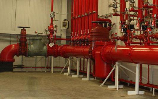
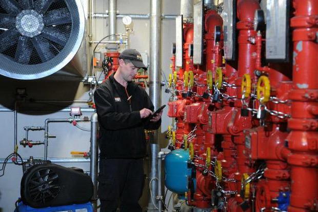
The fire water supply system is not only channels for supplying and supplying water. This is a whole infrastructure of devices, accessories and fixtures that are not always directly related to the maintenance of a water carrier. Nevertheless, almost all fire water supply systems are formed on the basis of steel pipes or their parts connected by welding. A faucet is also an obligatory component of the pipeline - wrought iron is used as the optimal material for this part or in last resort bronze is used. The faucet is designed to be connected to fire hoses if we are talking about mobile systems firefighting.
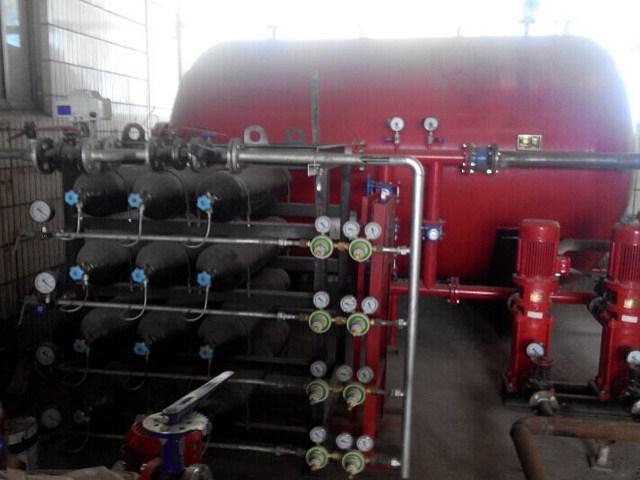
As already mentioned, one of the technological service points of the water channel is the pump. Could it be a pumping station? high blood pressure, capable of simultaneously serving several stationary sprinklers and mobile water supply channels. Also, as part of the water supply, regulatory and shut-off valves, switches, tanks, detectors, etc. The configuration of the placement of these devices may vary depending on what scheme the fire water pipeline is implemented directly in the structure of a particular object. So, there are external and domestic ways placement of communication.
Fire outdoor plumbing
The outdoor method of installation and operation is optimal when it comes to extinguishing large construction sites using special technical means. In particular, most systems of this type are focused on volumes up to 1000 m3. Concerning specific types objects, then the external fire water supply is used for almost all production facilities of classes C, D and D. It is also allowed to extinguish hangars, terminals, storage facilities.
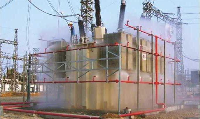
The water consumption in this case is about 10 l / s. This is an average value, since theoretically the maximum value can reach 35 l / s. However, in the case of residential and public facilities, there are limiting requirements for loads on water supply networks and distribution lines. The level of pressure with which water will be supplied is also preliminarily calculated. For example, the recommended value when using low pressure is 10 m. As the number of storeys increases, the force can increase at the rate of 4 m per floor. Despite attractive power indicators, outdoor type fire water supply is not always effective in combating internal sources of ignition. Accordingly, in such situations, internal water supply lines are more often used.
Fire internal plumbing
The standards for organizing an internal fire water supply system are defined in the relevant section of SNiP under the number 2.04.01-85. This water supply system provides fire extinguishing in industrial and public buildings, regardless of their categories. The height of the water supply can be 50 m, and the volume can reach 50 thousand m 3. For residential buildings the internal fire water pipeline on average supplies water at a speed of 1.5 l / s - provided that the diameters of the sleeves and trunks are adjusted to 38 mm.
It is thanks to the narrow jet that such systems can provide carrier supply to great heights. For the same reason, it is not advisable to use them in fire protection of low buildings. Most often, such structures are introduced into the infrastructure of hospitals, schools, universities, assembly halls, industrial premises.
The main task that the internal fire water supply system performs is to prevent the spread of fire at specific points. Therefore, if in the case of external water supply, the main goal is to supply mobile lines with sleeves, then internal complexes are guided by stationary sprinklers integrated into the ceilings of the premises. These can be deluge and sprinkler nozzles with different designs of nozzles, focused on dispersing drops or fog. Such devices are structurally complex, but their advantage is the ability to operate in automatic mode.
Water loss test
In the process of checking the system for water loss, it is assessed to what extent the pressure indicators on the main trunk correspond to the standard pressure. This check allows you to insure against overloads on the line and prevent accidents. Water loss tests are carried out twice a year. The time for testing is selected based on the period in which the most active water consumption at the facility is observed. For example, in the summer season. At the same time, communications should be checked with a minimum pressure in the main central line. This will allow to evaluate the possibility of the channel operation under the least favorable conditions.
In addition to pressure, checking the fire water supply also reveals the height of the compact segment of the jet, the amount of water consumed and the pressure at the valve. But in most cases it is not required to specifically make disparate measurements, since these indicators are interrelated. For example, the pressure on the main barrel will correspond to that in the crane. And at least the data on flow rate and jet height will fit into the standard.
The test for water loss itself is carried out sequentially on the fire hydrant, which has the greatest distance from the pumping station. If the line is loaded by several cranes, each of them must be activated. Including, adjacent taps and communications connected to the riser, to which the fire water supply is connected, are involved. At the same time, the requirements note that the pressure should be measured only at the main supply valve. Or, alternatively, the highest fire hydrant of the system can be controlled for convenience.
Measuring devices for testing
Pressure is the main measurement parameter, so the pressure gauge will also become the main tool in the work of the tester. Typically, measuring inserts with pressure gauges are used for such purposes. The ends of the inserts are provided in advance with special coupling heads.
As for the placement of the fixture, the position between the fire hose and the valve will be optimal. Directly the instrument pressure gauge is installed on the insert. If there is no possibility of a direct connection, then a flexible meter hose can be used, which will also allow you to transfer the degree of pressure to the pressure gauge scale.
Depending on the tasks of the water supply system, it may also include measurements of other parameters. For example, temperatures. But for this it is necessary to use either combined pressure gauges with a thermometer function, or industrial bimetallic devices with an external measurement sensor.
Checking system elements
In addition to checking the metrological and performance indicators of the water fire infrastructure, the technical condition of its components is also tested. The main object of the test is They are not always tested as part of the test for water loss, so a separate survey justifies itself.
The absence of breaks, deformations and defects on the surfaces of the trunk are the main criteria by which the internal fire water supply is also evaluated in this part. Requirements for both external and internal systems Initially, it is prescribed that for hand-held barrels, outlet diameters should be in the range of 13-19 mm. The average allowable value is 16 mm.
Sleeves are also checked for integrity and fit. In particular, the sleeve length can be 10, 15 or 20 m. As for the diameters, they vary from 51 to 66 mm. The specific size of the barrel and sleeve is selected based on the type of object being serviced and the requirements for fire fighting tactics.
By the way, checking the internal fire water supply also extends to the analysis of the quality of the sprinklers, which have their own design features. The performers evaluate their tightness, the quality of the water supply, the integrity of the element base and the quality of the connections. Almost every system also provides for the presence of water tanks, which can be called backup sources. Tanks of this type are checked for tightness and quality of connection with the communications of water lines.
Evaluation and registration of inspection results
In each case, the positive parameters will be different, since we can talk about an individual water supply project. The pressure indicator is considered as a basic criterion. Its value, in accordance with the normative proportions, will be superimposed on the optimal values that appear in the design solution. In any case, a positive check of the fire water supply will be such only if the integrity of the equipment and its compliance with specific technical parameters- length, diameter, etc.
After fixing the results of the check, a special document is drawn up. In particular, the tester writes a protocol in which the data on the results of testing the water loss potential are entered. This document contains information about the pressure at the barrel and valve. Along with this, a fire water supply act is drawn up, which indicates the time and place of the tests, as well as information about the building and the equipment being serviced. The characteristics of the tested communications are also detailed - for example, the type of barrel, sleeve material, crane dimensions, etc. Both documents must ultimately be signed by all members of the commission involved in the verification process.
Security Requirements
During the test, participants in the test must comply with safety rules. First of all, persons who have undergone appropriate training in handling fire water supply tools are allowed to the tests themselves. Each participant must have special clothing with a water-repellent coating. The characteristics of its tissues must correspond to the loads with which the examined water supply works.
Typically, such activities are carried out at special test sites, but in some cases, when it is necessary to evaluate the performance of the system as a whole, the verification is inevitably carried out at the site of equipment operation. In such situations, for example, water loss tests can only be carried out at times when the jet supply does not pose a threat to passing people and vehicles.
Inside the building, the fire safety of the water supply must also be ensured if the infrastructure of the interaction of the source, pump and sprinkler is checked. Since a comprehensive check may involve performing a number of collapsible manipulations, a complete set of tools and accessories suitable for a particular type of plumbing fittings should be prepared in advance.
Maintenance Requirements
Technical condition if the infrastructure is used regularly, it should be checked at least twice a year. Pipes, risers, reinforcing elements, connecting fittings, hoses with barrels, fire cabinets and other devices and fixtures are subject to verification. If necessary service staff performs repair work, changes worn parts, renews lubricating fluids in the motor filling of the pump and makes structural changes.
It should be borne in mind that the condition of the water supply can adversely affect not only the effectiveness of the fire extinguishing function, but also the safety of the building itself or the room to which it is attached. For example, under a high pressure load, even without a fire hazard, a pipe loop can voluntarily break out of a flimsy joint, causing property damage.
At the same time, the maintenance of the fire water supply also affects the performance of the line as such. Employees evaluate the quality of the pumping station and the stability of water supply from the main source. If necessary, they also make adjustments to the pressure and performance parameters of the equipment so that they optimally meet the requirements. fire safety for the current period.
Conclusion
The key to successful testing and efficient operation of the fire water pipeline is provided at the design and installation stage. Experts determine the rationality of laying circuits according to one or another scheme, taking into account the potential of hydrants, pumping stations and water supply lines. If conscientious work has been done at these stages, then the fire water pipeline is more likely to demonstrate compliance with both water loss standards and technical requirements.
In the future, the quality of operation of the water infrastructure will also depend on other factors. For example, how protected are the same hydrants in winter time. No less acute are the issues with a place for transport. near public buildings and production facilities Parking for fire trucks is required. At the very least, access roads and roads to the nearest sources of water supply should be prepared, regardless of the time of year.
It will be useful to provide for the nuances of energy supply. Usually, pumping stations with automatic control work from the mains, so the presence of a backup generator will make it possible to insure in the event of an emergency interruption of the power supply from the central line.
1. Grounds for the event:
Pursuant to the requirements of paragraph 55 of the Rules fire regime in Russian Federation(as amended by Decree of the Government of the Russian Federation of February 17, 2014 No. 113) the head of the organization ensures that the sources of external fire water supply and organizes inspections of their performance at least 2 times a year (in spring and autumn) with the preparation of relevant acts.
2. Purpose of the test:
Determine the possibility of obtaining compact jets with a height of at least 10 m at full fire water consumption and the location of the trunks at the level of the highest point of the tallest building of the facility (4.4. SP 8.13130.2009 as amended on 01.02.2011)
3. Conditions for holding events:
Fire hydrants must be checked under the following conditions:
water start-up only at positive temperatures; at an air temperature of 0 to -15 °C, only external inspection is allowed without running water.
at temperatures below -15 °C, opening the well covers for inspection is prohibited in order to avoid heat loss from the well itself.
4. Technical component of the events:
4.1. When checking fire hydrants, it is necessary to reflect:
condition of entrances to fire hydrants;
the placement of hydrants in wells should ensure the free installation of the well cover and the opening of the hydrant cover and the complete winding of the fire column;
the presence of pointers, the correspondence of the coordinates on the pointer to the actual location of the fire hydrant;
the presence and serviceability of the hatch and the cover of the well;
integrity and serviceability of covers and threads of the nipple, the upper square of the rod and the hydrant body; the presence of a hydrant riser cover;
the presence of water in the well, the body of the hydrant;
fastening the body of the hydrant to the stand;
tightness of the valve, ease of its opening and closing;
the state of the thread on the hydrant (by winding the fire column);
check the operation of the hydrant with the installation of a fire column and determine throughput(water consumption) hydrant;
specify the type and diameter of the conduit on which the hydrant is installed.
4.2. Minimum distances before internal surfaces wells that must match:
from the walls of the pipes (with a pipe diameter of up to 400 mm) - 0.3 meters; (from 500 to 600 mm) - 0.5 meters, (more than 600 mm) - 0.7 meters;
from the plane of the flange (with a pipe diameter of up to 400 mm) - 0.3 meters, (more than 400 mm) - 0.5 meters;
from the edge of the socket facing the wall (with pipe diameters up to 300 mm) - 0.4 meters, (300 mm) - 0.5 meters;
from the bottom of the pipe to the bottom (with a pipe diameter of up to 400 mm) - 0.25 meters, (from 500 to 600 mm) - 0.3 meters, more than 600 mm - 0.35 meters;
from the top of the valve stem with a rising spindle - 0.3 meters; from the flywheel of the gate valve with a non-rising spindle - 0.5 meters;
from the hydrant cover to the well cover not more than 450 mm vertically, and the clear distance between the hydrant and the top of the shell is not less than 100 mm;
the height of the working part of the wells must be at least 1.5 meters.
5. Water loss test:
5.1 Volume test
This method of measuring water consumption from water supply networks consists in determining the time for filling specially calibrated tanks, as a rule, with a capacity of 500-1000 liters. In this case, the calculation of water consumption is determined using the formula:
Q=V/t(l/s)
where: V is the volume of the tank, l; t is the tank filling time, s.
This method, compared with others, is the most accurate (the error does not exceed ± 1-2%).
5.2 Testing (measuring) with a water gauge
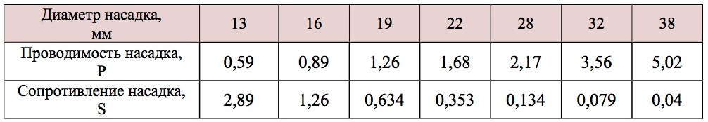
The barrel is additionally equipped with a pressure gauge and a set of interchangeable nozzles of various diameters. The flow rate of water from the barrel is determined by the formula for the outflow of liquids from the nozzles:
Q = √ H/ S or Q = PH -2, (l/s)
H - pressure in the water supply network, m water column;
S is the nozzle resistance;
P is the conductivity of the nozzle of the fire barrel.
To determine the conductivity P and S use the following data:
Table 1 Conductivity of fire nozzle nozzle
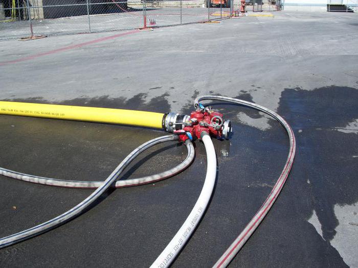
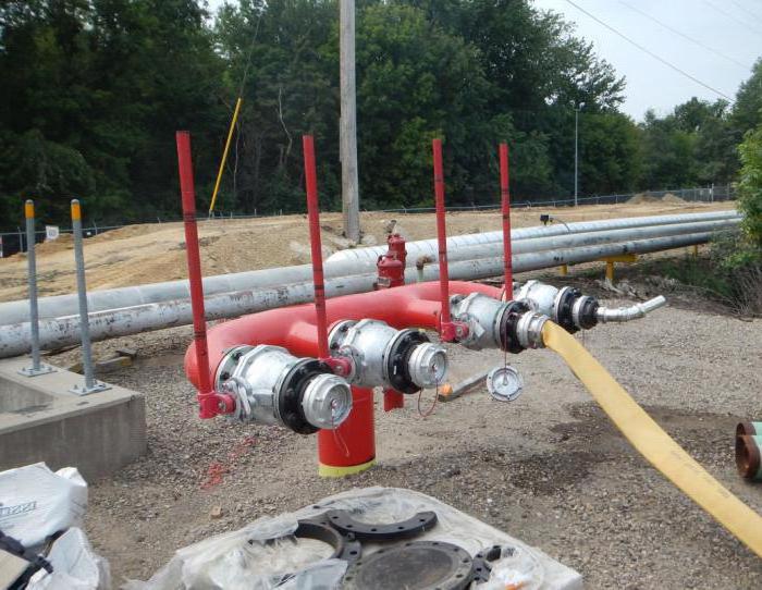
5.3. Test (measurement) using a fire column
When using this method, it is necessary to first calibrate the fire column, i.e. determine the flow of water depending on the reading of the manometer. The fire column is equipped with two pieces of pipes 500 mm long, 66 mm (2.5) or 77 mm (3) in diameter with connecting heads, a pressure gauge is installed on the column body. The total flow of water from a column installed on a fire hydrant is equal to the sum of the flow rates through two nozzles. The total water yield of the network is determined by the total water flow from several columns installed on the fire hydrants of the tested section of the water supply.
With a small water loss of water supply networks, you can use one pipe of the column, and attach a plug with a pressure gauge to the other pipe.
The water flow through the fire column is determined by the formula:
Q = PH -2, (l/s)
H - water pressure in the network, m;
P is column conductivity.
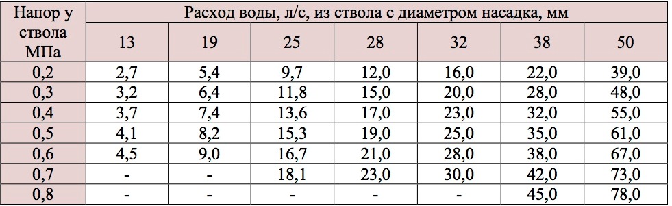
Table 2 Water output of a fire column
Number of open column nozzles Nozzle diameter Average column conductivity
Table 3 Conductivity of the fire column
In areas of water supply networks with small diameters (100-125 mm) and low pressure (10-15 m), it is more expedient to take water from the pump suction line from the well, filling it with water from the hydrant to the spout. In these cases, the flow rate of water from the hydrant is somewhat greater than the flow rate of water taken by the pump from the hydrant through the column.
Table 4 Water yield of the water supply network
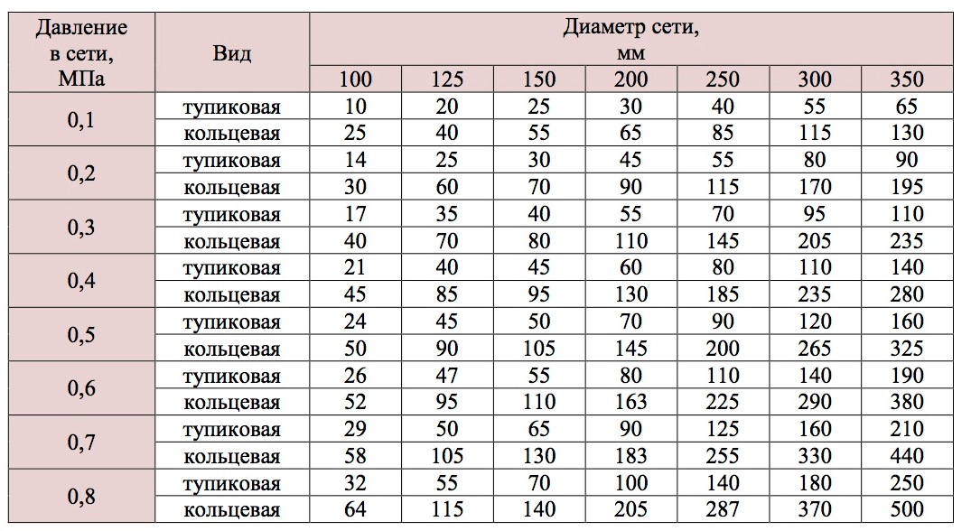
The water yield of the water supply network is determined using a fire column and a control and measuring device. Tests are carried out both at normal pressure and with the inclusion of booster pumps (pumping station).
For testing it is necessary:
install a fire column on a hydrant;
connect the smooth pipe of the instrument to the column;
open the fire hydrant until its drain channel is completely blocked;
measure free pressure;
compare the pressure gauge readings with tabular data, determine the water yield from the hydrant at the beginning of the water supply section, then repeat similar tests at the end of the water supply section. The arithmetic mean of the two values obtained during the tests will be the water yield of the section of the water supply network.
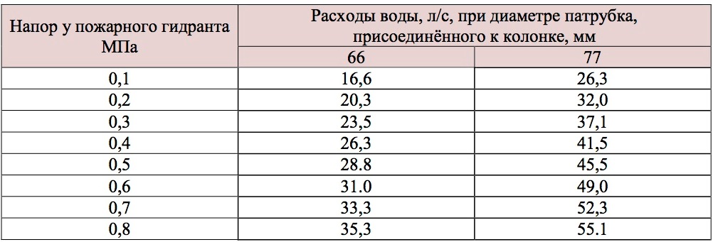
Water consumption through one branch pipe of a fire column, depending on its diameter and pressure at the hydrant.
6. List of characteristic malfunctions of fire hydrants
Plate:
there is no fire hydrant indicator (coordination plate);
The information on the plate is not correct or is not clearly visible.
Well:
covered with soil, debris, etc.; paved;
crowded with equipment, vehicles, etc.;
there is no entrance;
muted;
not closed (flowing);
low pressure in the network;
unfrozen;
there is no well drainage; shifted kit; no kit cover; no entrance;
ice does not allow to pronounce the opening.
Riser:
no riser;
low riser; the thread on the riser is knocked down; the riser is not fixed; the riser is clogged with soil; crack in the riser; no riser cover; shifted riser;
drain device does not work.
Stock :
no stock; the stem is broken; the stem is bent;
a long stem does not allow water to be started; large stem square; the edges of the stem are erased.
Flange:
bolts on the upper flange prevent the column from screwing on;
leak under the top or bottom flange; broken flange.
Highway:
disabled;
not hermetic
no bypass ring.
7. Terms and definitions:
Water supply network- the amount of water supplied per unit of time, depending on the pressure in the network and the type of water supply network.
Water pipes high pressure
- water supply free pressure, which ensures the height of the compact jet of the fire nozzle at least 10 m at the level of the highest point of the tallest building at full standard water flow for fire fighting. SNiP 2.04.02.
locking device- 1) a movable valve assembly designed to block its flow section; 2) a device designed to supply, regulate and shut off the flow of fire extinguishing agent. GOST R 51052; NPB 83.
Sources of outdoor fire fighting water supply: External water supply networks with fire hydrants and water bodies used for fire fighting purposes. (3.1 of SP 8.13130.2009 as amended, Amendment N 1 of 09.12.2010)
pressure gauge — 1) measuring device or a measuring apparatus for measuring pressure or differential pressure; 2) a device for measuring pressure or pressure difference. GOST 8.271; STSEV 4840.
Test Method- an organizational and methodological document that is mandatory for implementation, including a test method, test tools and conditions, sampling, algorithms for performing operations to determine homogeneous or several interrelated characteristics of object properties, forms of data presentation and assessment of accuracy, reliability of results, safety requirements and protection environment. GOST 16504.
Pressure fire hose- fire hose for transporting fire extinguishing agents under overpressure. GOST 12.2.047.
External fire water supply (NPV)- a system of structures and devices that delivers water through pipes from a water source to a place of consumption. (Clause 3.5 of SP 8.13130.2009 as amended, Amendment N 1 dated 09.12.2010)
fire column- a removable device installed on a fire hydrant for water extraction. GOST 12.2.047.
fire reservoir- a special reservoir or open reservoir designed to store the fire volume of water. SNiP 2.04.02
fire hydran t - a device for the selection of water from the water supply network to extinguish a fire. GOST 12.2.047.
Normal pressure fire pump I am a single or multi-stage firefighter centrifugal pump operating at outlet pressure up to 1.5 MPa (15 kgf/cm2). NPB 163.
fire stand- detail of the pipeline for the installation of a fire hydrant. GOST 12.2.047.
Maintenance- a set of operations or an operation to maintain the operability or serviceability of the product when used for its intended purpose, storage and transportation. GOST 18322.
Test conditions- a set of influencing factors and (or) modes of operation of the object during testing GOST 16504.
8. List of guidance documents:
1. The federal law 123 " Technical regulation on fire safety requirements.
2. Rules of the fire regime in the Russian Federation.
3. GOST 12.4.009-83 “Fire equipment for the protection of facilities”.
4. GOST 8220-85 “Underground fire hydrants. Specifications”.
5. GOST 12.4.026-76 “Signal colors and safety signs”.
6. SNiP 2.04.02-84 “Water supply. External networks and structures”.
7. GOST 25151-82 “Water supply. Terms and Definitions
8. Handbook of the head of fire fighting. - M., Stroyizdat Ivannikov V.P., Klyus P.P.
9. SP 8.13130.2009 Sources of external fire fighting water supply
9. List of outgoing documents:
ACT of checking serviceability and operability, testing the network of external fire-fighting water supply
Application No. 1 Technical certificate LPS systems
Annex No. 2 Test report of NPS for performance
Appendix No. 3 Fire hydrant inspection protocol
Annex No. 4 Test protocol for water loss of a water supply section
Appendix No. 5 Defective statement
We also recommend
 Switching power supply: repair and refinement
 Remote control of light
 Swimming lessons for preschool children
 Notes for the master - home household alarms
 Clock propeller on Atmega8
 Device and relay application examples, how to choose and connect a relay correctly Microcontroller and relay simple switching circuits