Metal-cutting machines, sale of metal-cutting equipment in the catalogue, descriptions, prices, characteristics. Types of metal cutting equipment
"Metal cutting machines"
Classification of machine tools by technological purpose, degree of automation, types of processing, dimensions, mass and accuracy.
by technological purpose: turning; drilling and boring; grinding, polishing, finishing, sharpening; combined and physico-chemical processing; gear and thread processing; milling; planing, slotting, lingering; cut. Each group is divided into 9 types: by purpose, design features, versatility, etc. By degree of automation: semi-automatic, automatic, CNC, GPM. By weight: light (up to 1t), medium (1-10t), heavy (10-100t), unique (above 100t). By accuracy: N - normal accuracy, P - increased accuracy, V - high accuracy, A - extra high accuracy, C - especially precise machines (machine master).
Dimensions of machines. Machine model and its designation.
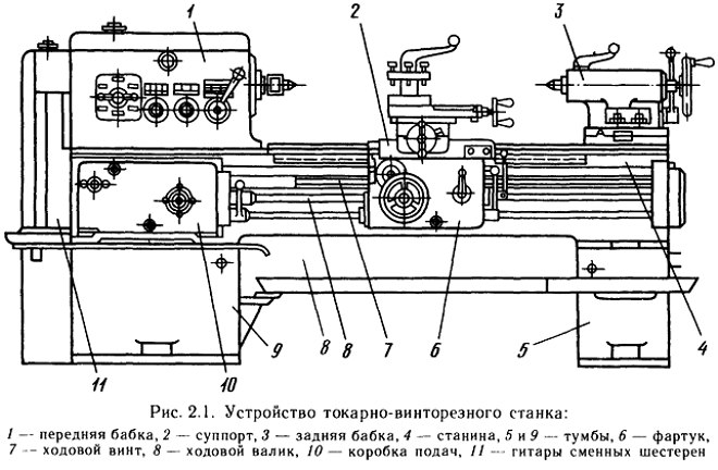
Size range- they call a group of the same type of machines similar in kinematic scheme, design, appearance, but having different basic parameters - sizes. The design of a machine of a given size designed for a given type of processing is called model. The first digit - indicates the group, the second - the type, the third and the fourth - characterizes the working space (basic size). The letter after the first or second digit indicates that the machine has been upgraded, and the letter after the numbers indicates a modification, a modification of the basic model of the machine. 16K20F3 - screw-cutting lathe(first 2 digits) with a center height of 200 mm of normal accuracy, F3 - numerical control, 3 coordinate movements in x, y, z.
Purpose, cutting patterns and technological capabilities of screw-cutting lathes.
The purpose of the machine is external and internal turning, cutting of right and left metric, inch, modular and pitch threads, single and multi-start threads with normal and increased pitch, face threads, etc. The machine is used in single and small-scale production. With proper operation on machines of medium size with normal accuracy, surfaces can be obtained according to 8 ... 7 degrees of accuracy with a roughness R a of not more than 3.2 ... 1.6 microns. On special high-precision machines, when using a tool from single crystals of diamonds, it is possible to obtain surfaces with a shape error determined by tenths of a micron and a roughness R z up to thousandths of a micron.
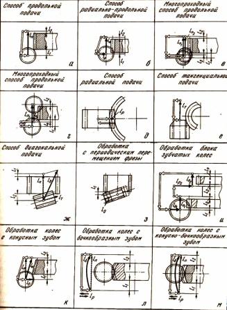
Purpose, cutting schemes and technological capabilities of gear hobbing machines.
Gear hobbing machines work according to the copying method and the bending method. Machines working according to the copying method are used for cutting cylindrical gears. In the case of installing a special tool, also for the manufacture of bevel wheels. The bending machines are designed for processing cylindrical gears with straight and helical teeth, as well as worm gears. Machine tools of classes H, P can provide the processing of wheels according to the 7th - 5th degree of accuracy (GOST 1643-81) when processing with worm cutters and 9 - 8th - when working with disk and finger cutters. Machine tools of classes B.A and C, when processing module wheels up to 12 mm with worm cutters, allow obtaining 4 - 2 degrees of accuracy. Master machines, which are modifications of class C machines, can provide the 1st degree of accuracy when processing worm wheels.
Purpose, classification, basic movements and technological capabilities of milling machines.
They are designed for processing external and internal, flat, shaped surfaces, ledges, grooves, straight and helical grooves, splines on shafts, cutting gears, etc. They produce universal, specialized and special milling machines according to their design. The shaping motions are the rotation of the cutter (main motion) and the feed motion that inform the workpiece or cutter. Main motion drives and feed drives are made separately. For a CNC machine, according to accuracy class P, the following tolerances (µm) are established: accuracy of linear one-sided positioning with a travel length of more than 400 to 1000 mm - 25; on the roundness of the hole processed by the cutter with contour PU - 12; for the straightness of rounded edges - 20.
Purpose, cutting scheme and technological capabilities of gear shaping machines.
On these machines, spur gears of external and internal gearing are cut, and in the presence of a copier and a helical cutter, helical gears are cut. In addition, blocks of several wheels can be cut on these machines. The advantage of these machines is the continuity of work without loss of time to approach the workpiece and exit from it. Setting up the machine for cutting helical gears is no different from the usual one. In this case, copiers with screw guides are installed, which impart additional rotation to the copier. As a result of rotational and reciprocating motion, the teeth of the cutter will move along a helix, the angle of inclination of which must be equal to the angle of inclination of the helix of the teeth of the cut wheel on the dividing cylinder.
Purpose, classification, basic movements and technological capabilities of boring machines.
Boring machines are designed for processing body parts. They can be used for boring, drilling, milling, countersinking, threading, etc. Boring machines are divided into the following types: horizontal boring machines; coordinate boring machines; diamond boring (finishing and boring) machines. When using additional interchangeable units (milling heads, faceplate), it is possible to mill mutually perpendicular planes, machine outer cylindrical surfaces, etc. Possibility of processing blanks from four sides without reinstallation. Coordinate boring machines can also be used as measuring machines for controlling linear dimensions along three axes, angular dimensions of center-to-center distances. It is possible to carry out precise marking in the idea of punching, as well as to make division and marking on metal surfaces. On finishing machines, a high accuracy of hole processing is achieved - a deviation from roundness of 3 ... 5 microns and a surface roughness R a = 0.16 ... 0.63 microns.
Aggregate machines for processing body parts, their technological capabilities and classification.
Aggregate machines are called special machines, which are assembled from functionally independent normalized and partially special units and parts. On aggregate machines, drilling, boring, threading, reaming of holes and their countersinking and countersinking, grooving, end trimming, and milling are performed. In such machines, the workpiece is usually stationary, which allows it to be processed simultaneously by a large number of tools from several sides. Classification: 1) depending on the dimensions of the processed workpieces, the speakers are divided into three groups, differing in size, weight and unified units used: Medium-sized speakers equipped with quill power heads with a flat-cam feed drive with a power of 1.1 ... 3 kW; Speakers of large sizes, equipped with hydraulic or electromechanical tables, on which spindle units are installed. 2) according to the absence or presence of a transport device for the periodic movement of the processed workpiece, the AU is divided into single- and multi-position ones.
Automatic lines, their purpose, classification and technological capabilities. rotary lines.
Automatic lines are called production lines of machines and units connected into a single system in which the entire complex of technological processes takes place without the direct participation of the worker. They are classified: 1) according to the degree of combination of processing time and transportation of workpieces of an automatic line: - stationary, - rotary, - conveyor; 2) by the number of threads: - single-thread (each operation is performed on one workpiece), -multi-thread (one and the same operation is performed on several workpieces); 3) according to the number of types of simultaneously processing blanks: - single-subject, - multi-subject. The flexible automatic line is readjusted to the given one and reconfigured to the new part nomenclature. Rotary lines - a set of rotary automatic machines on which workpieces are processed, made in the process of continuous transportation together with the cutting tool. Main Feature rotary lines is the combination in time of transport blanks and their processing.
Machine modules and flexible machine systems, their composition and technological capabilities.
Purpose, technological capabilities and classification of grinding machines.
Unlike blade tools, grinding wheels work by touch. With the rotational movement of the circle in the zone of its contact with the workpiece, part of the grains cut off the material in the form of a very large number of thin chips (10 8 ppm). The cutting process with each grain is almost instantaneous. Classification of grinding machines according to the shape of the surface to be treated: flat - surface grinding, face grinding, longitudinal grinding; cylindrical - circular grinding (center), centerless grinding; screw - thread grinding; running (involute) - gear grinding; shaped - profile grinding. Grinding machines are characterized by high accuracy, which allows to ensure high quality of processing, determined by accuracy, which allows to ensure high quality of processing, determined by the accuracy of dimensions (2 - 4 microns and turning), shape (for example, non-circularity 0.3 - 0.5 microns, cylindricity 1 - 2 µm, flatness 2 µm) and the location of the treated surface, as well as its roughness (R a - 0.63 - 0.16 µm). Dimensional accuracy during grinding is determined by small depths of cut (0.05 - 0.005 mm or less), which requires micro-movement of the assembly
Purpose, classification, basic movements and technological capabilities of drilling machines.
Designed for processing through and blind holes with end tools (drills, countersinks, reamers, taps). Types of operations performed on drilling machines: drilling, reaming, countersinking, reaming, tapping. Using special tools and fixtures on drilling machines, you can bore a large diameter hole - trepanning, lapping a hole, trimming ends (zikovka). The following types of drilling machines are most common: vertical drilling single-spindle machines, radial drilling machines, desktop single-spindle vertical drilling machines, machines for deep drilling (horizontal layout), aggregate drilling machines which consist of normalized units. Can have up to 100 or more spindles.
Multi-purpose machines and their technological capabilities.
More than 70% of parts of the type of bodies of revolution, in addition to turning, require additional operations: machining holes (drilling, boring, etc. from which they are located // prependicularly or at an angle to the axis of the part, milling under different angles grooves, volumetric milling. The creation of multi-purpose machines provides complete complex machining of a part on one machine in one setup. Significantly improves machining accuracy and machining performance. The polar coordinate drive, depending on the processing conditions, must provide either position control (mechanical division), or continuous control with a resolution of 0.001 and switching on at a frequency of 0.2-0.25 rpm.
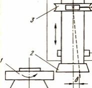
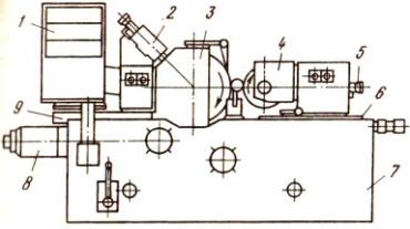
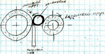
Purpose, main units and cutting scheme on centerless grinding machines.
They are used in large-scale production for high-performance grinding of surfaces such as bodies of revolution of small diameter and large length, as well as workpieces without center holes. 1 - control block, 2 and 5 - dressing devices for the grinding wheel and driving circle, 3 - grinding headstock, 4 - headstock of the leading circle, 6 - slide of the headstock of the leading circle, 7 - machine bed, 8 - feeder for plunging, 9 - sled sanding bean.
Metal cutting machines manufactured domestic producers, are divided into several categories, which characterize the corresponding classification. You can determine which category this or that equipment belongs to by its marking, which says a lot to those who understand it. However, no matter what category the metal-cutting device belongs to, the essence of processing on it comes down to the fact that the cutting tool and the part make shaping movements, and it is they that determine the configuration and dimensions of the finished product.
The most common types of metal-cutting machines: 1-6 - turning, 7-10 - drilling, 11-14 - milling, 15-17 - planing, 18-19 - broaching, 20-24 - grinding.
Types of metal cutting equipment
Metal-cutting machines, depending on the purpose, are divided into nine main groups. These include the following devices:
- turning- all varieties (marked with the number "1");
- drilling and boring– machines for drilling operations and boring (group “2”);
- grinding, polishing, finishing– metal-cutting machines for finishing, grinding, sharpening and polishing technological operations(group "3");
- combined– metal cutting devices special purpose(group "4");
- carving and gear cutting- machines for processing elements of threaded and gear connections (group "5");
- milling– machines for performing milling work(group "6");
- slotting, planing and broaching- metal-cutting machines of various modifications, respectively, for planing, grooving and broaching (group "7");
- split- equipment for cutting work, including saws (group "8");
- different- examples of such metal-cutting units - centerless-peeling, saw-cutting and others (group "9").
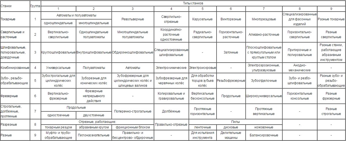
Groups and types of metal cutting machines (click to enlarge)
In addition, machine tools can be one of the following types:
- multi- and single-spindle, specialized (semiautomatic and automatic), copy multi-cutting, revolving, drilling and cutting, carousel, frontal and special;
- equipment for performing technological operations of boring and drilling: multi- and single-spindle, semi-automatic, vertical, horizontal and radial type, boring devices of coordinate, diamond and horizontal type, different drilling models;
- different types grinding machines (flat, internal and circular grinding), roughing and polishing equipment, grinding and specialized units;
- types of metalworking machines designed for processing elements of gear and threaded connections: gear cutting (including those intended for processing conical wheels), gear cutting - for cylindrical gears, gear hobbing, threading, threading and gear grinding, gear finishing, testing, thread milling, devices for processing the ends of teeth and elements of worm pairs;
- metal-cutting machines belonging to the milling group: console (vertical, horizontal and universal models) and consoleless (vertical devices, longitudinal, copying and engraving models);
- planing equipment and models for a similar purpose: longitudinal machines on which one or two racks are installed; horizontal and vertical broaching devices;
- cutting equipment: equipped with either a smooth metal disc, cutter or saws various designs(tape, disk, hacksaw); correct-cutting types of metalworking machines;
- other types of machines for processing metal blanks: dividing, used to control drills and grinding wheels, filing, balancing, straightening and centerless roughing, sawing.
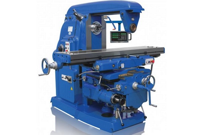
Vertical- milling machine— one of the representatives of an extensive milling group
The classification of metal-cutting machines is also carried out according to the following parameters:
- by weight and overall dimensions of the equipment: large, heavy and unique;
- by level of specialization: machines designed for processing workpieces of the same size - special; for parts with different, but the same size - specialized; universal devices, on which you can process parts of any size and shape;
- according to the degree of processing accuracy: increased - P, normal - N, high - B, especially high accuracy - A; also distinguish between machines on which you can perform particularly precise processing - C, they are also called precision.
Machine marking
The classification of equipment designed for processing metal blanks suggests that, having seen its marking, any specialist will immediately be able to tell which metal-cutting machine is in front of him. This marking contains alphabetic and numeric characters that indicate individual characteristics devices.
The first digit is the group to which the metal-cutting machine belongs, the second is the type of device, its type, the third (and in some cases the fourth) is the main unit size.
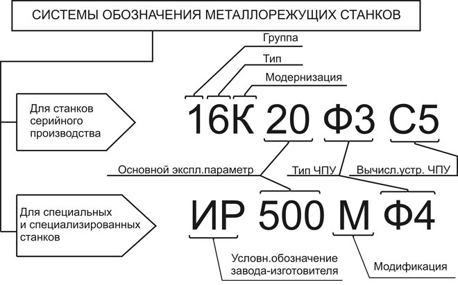
After the numbers listed in the model marking, there may be letters that determine whether the model of the metal cutting machine has special characteristics. Such characteristics of the device may include its level of accuracy or an indication of a modification. Often in the designation of the machine, the letter can be found already after the first digit: this indicates that you have a modernized model in front of you, in the typical design of which any changes have been made.
As an example, you can decipher the marking of the machine 6M13P. The numbers in this designation indicate that we have a milling machine (“6”) of the first type (“1”), which belongs to the 3rd standard size (“3”) and allows processing with increased accuracy (letter “P” ). The letter "M", present in the marking this device, indicates that it has undergone modernization.
Automation levels
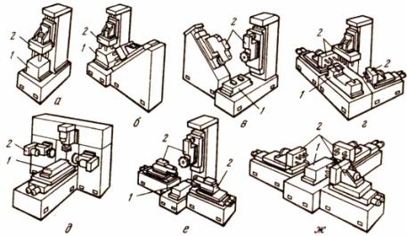
Types of lathes, as well as devices for any other purpose, which are used in mass and large-scale production, are called aggregate. They got this name due to the fact that they are completed from the same type of units (assemblies): beds, working heads, tables, spindle units and other mechanisms. Completely different principles are used in the creation of machines that are necessary for small-scale and single-piece production. The design of such devices, which are highly versatile, can be completely unique.
The classification of lathes (as well as equipment of any other categories) according to the level of automation implies their division into the following types:
- manual models, all operations on which are carried out in manual mode;
- semi-automatic, in which part of the technological operations (setting the workpiece, starting the device, removing the finished part) is performed manually (all other operations related to auxiliary ones are carried out automatically);
- automatic, for the operation of which it is only necessary to set the processing parameters, they perform all other operations independently, in accordance with a given program;
- CNC metal-cutting units (all processes on such machines are controlled by a special program that contains an encoded system of numerical values);
- metal-cutting equipment belonging to the category of flexible automated modules.
The most prominent representatives of metal-cutting machine tools are CNC devices, the operation of which is controlled by a special computer program. Such a program, which is entered into the memory of the machine by its operator, determines almost all the parameters of the operation of the unit: spindle speed, processing speed, etc.
All types of metalworking machines equipped with a CNC system contain the following typical elements in their design.
- The operator's console (or console), through which a computer program is stored in the memory of the machine that controls its operation. In addition, with the help of such a remote control, you can also perform manual control of all parameters of the unit.
- Controller - important element CNC system, with the help of which not only control commands are generated that are transmitted to the working elements of the equipment, and the correctness of their execution is controlled, but also all necessary calculations. Depending on the degree of complexity of the unit model, both a powerful compressor and a conventional microprocessor can be used as a controller to equip it.
- A screen or display that acts as a command and control panel for the operator. Such an element allows you to monitor the operation of the metal-cutting machine in real time, control the processing process, and, if necessary, quickly change the parameters and settings.
The principle of operation of metalworking machines equipped with a CNC system is simple. A program is preliminarily written that takes into account all the requirements for processing a particular workpiece, then the operator enters it into the machine controller using a special programmer. The commands embedded in such a program are given to the working elements of the equipment, and after their execution, the machine automatically turns off.
The use of metal-cutting machines equipped with a numerical program management, allows you to perform processing with high accuracy and productivity, which is the reason for their active use to equip industrial enterprises producing products in large series. Such units are due to high level of their automation are perfectly integrated into large automated lines.
Machine design
All machines belonging to the category of metalworking have many common features in its design. In fact, the device and technical characteristics of such units must ensure the correct execution of technological movements of two types:
- the feed motion that the cutting device or the workpiece itself makes;
- the movement by which cutting is carried out.
To perform these movements, as well as to ensure the stability of the functioning of all other elements of metalworking equipment, its design includes the following working bodies:
- control system responsible for starting and stopping the machine, monitoring all parameters of its operation;
10.09.2011 18:36
The most common type of equipment in modern machine-building and instrument-making production were processing machines construction materials by chip removal. The classification of machine tools, adopted back in the USSR, was based on the technological method of processing workpieces, characterized by the type of surfaces being machined, the type of machine tool and the type cutting tool. A variety of machined parts and applied processing methods predetermined the existence of many types and models of machine tools general engineering(machines of precision instrumentation do not yet have a clear classification system accepted by the standard).
The most common types of metal cutting machines
Depending on the nature of the work performed on them and the cutting tools used, the machines are divided (classified) into groups. According to the classification proposed by the Moscow Experimental Research Institute of Metal-cutting Machine Tools (ENIMS) in the USSR, all mass-produced machine tools were divided into 11 groups. Each of these groups of machines, in turn, is divided into ten varieties (types) 0-10 according to the following main features:
- technological features of the machine (peeling, finishing);
- degree of automation;
- the number of the most important working bodies (or tools) and their location, etc. Each type has 10 standard sizes.
Zero group and zero type of machines are reserved.
Machine tool groups
- Zero group and zero type of machines are standby.
- The first group - lathes(positions 1 - 6 in the figure) this group includes machines that are designed for processing surfaces of rotation. When processing on machines of this group, the cutting movement is due to the rotation of the workpiece.
- The second group - drilling and boring machines(in the figure positions 7 - 10). The main purpose of the machines of this group is the processing of round holes in the part. The cutting motion comes from the rotation of the machine tool. In some types of machines of this group, movement is imparted by moving the table with the fixed part.
- The third group - grinding machines(in the figure positions 20-24). In this group of machines, processing is carried out using abrasive grinding wheels.
- Fourth group - milling machines(in the figure positions 11-14). In this group of machines, processing (cutting) is performed using cutters.
- Fifth group - planing machines(in the figure positions 15-17). This group of machines includes machines whose common feature is the use of the rectilinear reciprocating movement of the cutter or workpiece as the cutting movement.
- Sixth group - broaching machines (in the figure positions 18 and 19). This group includes machine tools that use broaching as a cutting tool.
- The seventh group - polishing and finishing machines. The unifying factor of this group is abrasive cutting tools: abrasive belts, powders, pastes, abrasive bars.
- Eighth group - gear machines. This group of machines is intended for the processing of wheel teeth, gear grinding machines are also included here.
- The ninth group - threading machines. This group of machines is intended for the manufacture of threads (except for lathes).
- The tenth group - various and auxiliary machines. Machine tools not included in other groups.
This classification allows assign a code number to each serial production machine(index) - type and model symbol. The index consists of three to four digits: the first digit indicates the group, the second - the type (variety) of the machine within this group, the third and fourth - characterize one of the most important dimensions of the machine or workpiece. Uppercase letter after the first digit indicates a machine upgrade. The letter after all numbers indicates a modification (modification) of the basic model of the machine or technological features it (for example, increased accuracy). For example, let's decipher the designation of the machine mod. 3740. The number 3 means that the machine belongs to the group of grinding machines; number 7 indicates its type - surface grinding with round table; the last two digits indicate the largest table diameter - 400 mm. Machine mod. 2135: number 2 means that the machine of the second group (drilling), number 1 - vertical, 35 - the maximum allowable nominal diameter drilling in medium strength steel 650 MPa. Model 2H135 is a modernized machine.
To designate models of specialized and special machine tools in the USSR, each machine-tool plant was assigned an index of one or two letters. These letters are supplemented with numbers indicating the serial number of the special machine being produced (for example, AM - Minsk Plant of Automatic Lines; MP - Minsk Machine-Tool Plant named after Kirov; MK - Moscow Machine-Tool Plant "Red Proletarian", etc.).
According to the degree of universality and specialization, machines are distinguished
- universal, or general purpose, on which various operations are performed for processing parts of various nomenclature (screw-cutting lathe, revolving, etc.);
- specialized - for processing parts of one or a few names, similar in configuration, but having various sizes, used mainly in mass production;
- special - for processing one part or parts of the same standard size, used in mass production, sometimes in large-scale production.
Depending on the mass, metal-cutting machines of general engineering are divided into categories
- light - up to 1 ton
- medium - up to 10 tons
- heavy - over 10 tons
And the latter, in turn, into large ones - 10-30 tons, actually heavy - 30-100 tons and especially heavy (unique) - more than 100 tons.
According to the degree of accuracy, classes of machine tools are distinguished
- normal accuracy - H;
- increased accuracy - P;
- high accuracy - B (precision);
- especially high accuracy - A
- especially precise - C ("master"-machines made individually).
Machining accuracy is mainly determined by the machining method and the degree of accuracy of the machine. So, machines of normal accuracy are intended mainly for processing medium-sized parts within qualifications 7-9.
Machine tools with program control (PU)
Machine tools with program control (PU) can be with systems cyclic program control(CPU) or with numerical control systems(CNC). Machines with digital indication and pre-setting of coordinates are allocated in a separate group. In machines with a CPU (they have the index C in the model designation), only technological information is entered into the program carrier, and dimensional adjustment is provided on the machine with stops. In CNC machines (indices F2, FZ, F4), control is carried out from a program carrier, in which both technological and dimensional information are encoded. Machines with digital indication and pre-setting of coordinates (index F1) have an electronic device that sets the coordinates of the points of the surface to be machined, and the cross table is brought to the required position. The cross table has a feedback sensor, each instantaneous position of the table is displayed on the remote control (digital indication). In these machines (most often boring machines), either a pre-set of coordinates or a digital indication is usually used. For overall assessment the quality of the machine use a system of technical and economic indicators. Among the most important indicators that determine the perfection of the design of the machine in comparison with other machines of a similar purpose are: productivity, processing accuracy, degree of automation, manufacturability, metal consumption, footprint, cost.
Metal-cutting machines, depending on the purpose, are divided into nine main groups. These include the following devices:
1. turning- all types of lathes of the turning group (in the marking they are indicated by the number "1");
2. drilling and boring- machines for drilling operations and boring (group "2");
3. grinding, polishing, finishing- metal-cutting machines for finishing, grinding, sharpening and polishing technological operations (group "3");
4. combined- metal-cutting devices for special purposes (group "4");
5. carving and gear cutting- machines for processing elements of threaded and gear connections (group "5");
6. milling- machines for milling (group "6");
7. slotting, planing and broaching- metal-cutting machines of various modifications, respectively, for planing, grooving and broaching (group "7");
8. split- equipment for cutting work, including saws (group "8");
9. different- examples of such metal-cutting units - centerless-peeling, saw-cutting and others (group "9").
Groups and types of metal cutting machines (click to enlarge)
In addition, machine tools can be one of the following types:
· multi- and single-spindle, specialized (semiautomatic and automatic), copying multi-cutting, revolving, drilling and cutting, carousel, frontal and special types of lathes;
equipment for performing technological operations of boring and drilling: multi- and single-spindle, semi-automatic, vertical, horizontal and radial type drilling machines, coordinate, diamond and horizontal type boring machines, various drilling models;
· various types of grinding machines (flat, internal and circular grinding), roughing and polishing equipment, tool-grinding and specialized units;
Types of metalworking machines designed for processing elements of gear and threaded joints: gear cutting (including those designed for processing conical wheels), gear cutting machines for cylindrical gears, gear hobbing, thread cutting, threading and gear grinding, gear finishing, testing, thread milling , devices for processing the ends of teeth and elements of worm pairs;
· metal-cutting machines belonging to the milling group: cantilever (vertical, horizontal and universal models) and non-cantilever (vertical devices, longitudinal, copying and engraving models);
planing equipment and models for similar purposes: longitudinal machines on which one or two racks are installed; horizontal and vertical broaching devices;
cutting equipment: equipped with an abrasive wheel or a smooth metal disc, a cutter or saws of various designs (tape, circular, hacksaw); correct-cutting types of metalworking machines;
Other types of machines for processing metal blanks: dividing, used to control drills and grinding wheels, filing, balancing, straightening and centerless roughing, sawing.
Vertical milling machine - one of the representatives of an extensive milling group
The classification of metal-cutting machines is also carried out according to the following parameters:
· by weight and overall dimensions of the equipment: large, heavy and unique;
By level of specialization: machines designed for processing workpieces of the same size - special; for parts with different, but the same size - specialized; universal devices on which you can process parts of any size and shape;
· according to the degree of processing accuracy: increased - P, normal - N, high - B, especially high accuracy - A; also distinguish between machines on which you can perform particularly precise processing - C, they are also called precision.
Machine marking
The classification of equipment designed for processing metal blanks suggests that, having seen its marking, any specialist will immediately be able to tell which metal-cutting machine is in front of him. This marking contains alphabetic and numeric characters that indicate the individual characteristics of the device.
The first digit is the group to which the metal-cutting machine belongs, the second is the type of device, its type, the third (and in some cases the fourth) is the main unit size.
Deciphering the marking of metal-cutting machines
After the numbers listed in the model marking, there may be letters that determine whether the model of the metal cutting machine has special characteristics. Such characteristics of the device may include its level of accuracy or an indication of a modification. Often in the designation of the machine, the letter can be found already after the first digit: this indicates that you have a modernized model in front of you, in the typical design of which any changes have been made.
As an example, you can decipher the marking of the machine 6M13P. The numbers in this designation indicate that we have a milling machine (“6”) of the first type (“1”), which belongs to the 3rd standard size (“3”) and allows processing with increased accuracy (letter “P” ). The letter "M", present in the marking of this device, indicates that it has been upgraded.
Automation levels
Types of lathes, as well as devices for any other purpose, which are used in mass and large-scale production, are called aggregate. They got this name due to the fact that they are completed from the same type of units (assemblies): beds, working heads, tables, spindle units and other mechanisms. Completely different principles are used in the creation of machines that are necessary for small-scale and single-piece production. The design of such devices, which are highly versatile, can be completely unique.
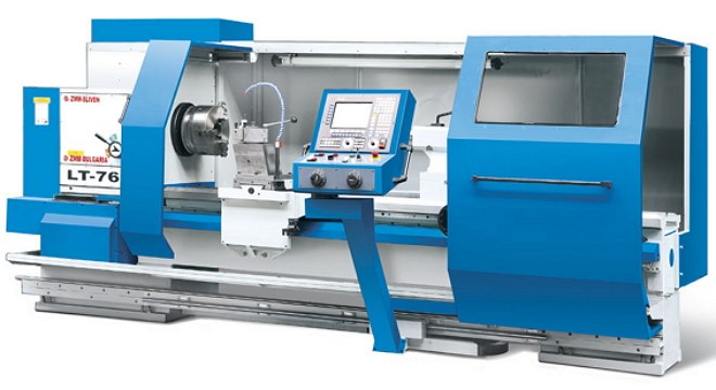
CNC lathe
The classification of lathes (as well as equipment of any other categories) according to the level of automation implies their division into the following types:
1. manual models, all operations on which are carried out in manual mode;
2. semi-automatic, in which part of the technological operations (setting the workpiece, starting the device, removing the finished part) is performed in manual mode (all other operations related to auxiliary ones take place in automatic mode);
3. automatic, for the operation of which it is only necessary to set the processing parameters, they perform all other operations independently, in accordance with the specified program;
4. CNC metal-cutting units (all processes on such machines are controlled by a special program that contains a coded system of numerical values);
5. metal-cutting equipment belonging to the category of flexible automated modules.
The most prominent representatives of metal-cutting machine tools are CNC devices, the operation of which is controlled by a special computer program. Such a program, which is entered into the memory of the machine by its operator, determines almost all the parameters of the operation of the unit: spindle speed, processing speed, etc.
CNC can be equipped with even the most compact desktop machines
All types of metalworking machines equipped with a CNC system contain the following typical elements in their design.
· The operator's console (or console), through which a computer program is stored in the memory of the machine that controls its operation. In addition, with the help of such a remote control, you can also perform manual control of all parameters of the unit.
· The controller is an important element of the CNC system, with the help of which not only the control commands are formed, transmitted to the working elements of the equipment, and the correctness of their execution is controlled, but also all the necessary calculations are made. Depending on the degree of complexity of the unit model, both a powerful compressor and a conventional microprocessor can be used as a controller to equip it.
· A screen or display that acts as a command and control panel for the operator. Such an element allows you to monitor the operation of the metal-cutting machine in real time, control the processing process, and, if necessary, quickly change the parameters and settings.
The principle of operation of metalworking machines equipped with a CNC system is simple. A program is preliminarily written that takes into account all the requirements for processing a particular workpiece, then the operator enters it into the machine controller using a special programmer. The commands embedded in such a program are given to the working elements of the equipment, and after their execution, the machine automatically turns off.
The use of machine tools equipped with numerical control allows processing with high accuracy and productivity, which is the reason for their active use to equip industrial enterprises that produce products in large batches. Such units, due to their high level of automation, are perfectly integrated into large automated lines.
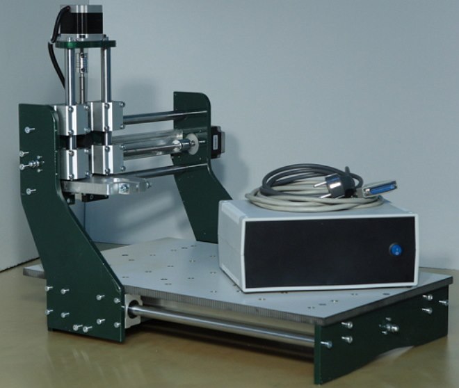
Screw-cutting lathe device
Machine design
All machines belonging to the category of metalworking have many common features in their design. In fact, the device and technical characteristics of such units must ensure the correct execution of technological movements of two types:
the feed motion that the cutting device or the workpiece itself makes;
The movement by which cutting is carried out.
To perform these movements, as well as to ensure the stability of the functioning of all other elements of metalworking equipment, its design includes the following working bodies:
a control system responsible for starting and stopping the machine, monitoring all parameters of its operation;
a node with the help of which the movement from the electric motor is converted and transmitted to the actuator;
The drive itself, which can be electrical, mechanical, pneumatic or hydraulic.
A metal cutting machine is a machine designed to process workpieces in order to form specified surfaces by removing chips or by plastic deformation. Processing is carried out mainly by cutting with a blade or abrasive tool. Machine tools are also used for smoothing the surface of the part, for rolling the surface with rollers. Metalworking machines carry out cutting of non-metallic materials, for example, wood, textolite, nylon and other plastics. Special machines also process ceramics, glass and other materials.
Metalworking machines are classified according to various criteria, depending on the type of processing, the cutting tool used and the layout.
The most common types of metal cutting machines
Classification
Metal-cutting machines, depending on the nature of the work performed and the type of cutting tools used, are divided into 11 groups (see figure).
- Group of lathes(pos. 1 - 6) consists of machines designed for processing surfaces of rotation. The unifying feature of the machines of this group is the use of the rotational movement of the workpiece as a cutting movement.
- Group of drilling machines(pos. 7 - 10) also includes boring machines. The unifying feature of this group of machines is their purpose - the processing of round holes. The cutting motion is the rotational motion of the tool, which is usually also accompanied by a feed motion. In horizontal boring machines, the feed can also be carried out by moving the table with the workpiece.
- Group of grinding machines(pos. 20 - 24) is combined on the basis of the use of abrasive grinding wheels as a cutting tool.
- Group of polishing and finishing machines combined on the basis of the use of abrasive bars, abrasive belts, powders and pastes as a cutting tool.
- Group of gear machines includes all machines that are used for processing the teeth of wheels, including grinding.
- Group of milling machines(pos. 11 - 14) consists of machines that use multi-blade tools - milling cutters as a cutting tool.
- Planer group(Pos. 15 - 17) consists of machines in which a common feature is the use of the rectilinear reciprocating movement of the cutter or workpiece as the cutting movement.
- Group of cutting machines includes all types of machines designed for cutting and sawing rolled materials (rods, angles, channels, etc.).
- Group of broaching machines(vines 18 and 19) has one common feature: use as a cutting tool of special multi-blade tools - broaches.
- Group of threading machines includes all machines (except machines of the turning group) designed specifically for the manufacture of threads.
- Group of miscellaneous and auxiliary machines unites all machines that do not belong to any of the above groups.
Table of machine tool figures
| Name of machines | Cipher groups |
Type code | |||||||||
| 0 | 1 | 2 | 3 | 4 | 5 | 6 | 7 | 8 | 9 | ||
| Reserve | 0 | - | |||||||||
| Turning | 1 | Automatic and semi-automatic: | Turning- revolving |
Drilling- cutting |
carousel | Turning and frontal |
Multi-cutting and copying |
Specialized wrought |
Different turning |
||
| specialized wrought |
one-spin- sensible |
multi-spin- sensible |
|||||||||
| Drilling and boring | 2 | - | Vertical- drilling |
semi-automatic | Coordinate boring | Radially- drilling |
Horizontally- boring |
Diamond boring |
Horizontally- drilling |
Different drilling |
|
| one-spin- sensible |
multi-spin- sensible |
||||||||||
| Grinding and finishing | 3 | Krugloshli- foval |
Intra- foval |
Peeling- grinding |
Specialized honed grinding |
- | Sharpening | Surface grinding | Lapping, polishing, honing, finishing | Various figurative | |
| Electro- physical and electrical chemical |
4 | - | Light beam | - | Electro- chemical |
Electro- spark |
- | Electro- erosion, ultrasonic piercing |
Anode- mechanical cutting |
- | |
| Tooth-and thread-machining- ing |
5 | Thread- rifled |
Gear shaping for processing cylindrical calic wheels |
Gear cutting for processing bevel wheels | Gear hobbing for machining cylindrical wheels and splined shafts |
For cutting worm wheels | For processing the ends of the teeth of the wheels | thread-free cereals |
Dental finishing nye, check- nye and running |
Tooth and thread boslifoval- nye |
Various gear and thread I process- shie |
| Milling | 6 | - | Vertical- milling cantilever |
Milling non- discontinuous action |
Longitudinal single-column nye |
Copy- nye and gravel roving |
Vertical- consoleless |
Longitudinal two-column nye |
Console- milling operations rational |
Horizon- tal- milling cantilever |
Various milling |
| Planing, slotting, broaching | 7 | Longitudinal | Cross- planing |
Slotting | Long-drawn horizontal nye |
Broaching vertical for pulling | - | Various planers | |||
| one- rack |
two- rack |
internal | outdoor | ||||||||
| Split | 8 | Cut-off, equipped | Right- cutting |
Saws | - | - | |||||
| turning tool | grinding circle |
smooth or notched disc | tape | disk | Hacksaw | ||||||
| Different | 9 | Coupling and pipe battling |
Saw-notched | Right- and centerless peeling |
Balancing | For test- tools |
Divider- machines |
Balancer- military |
- | - | |
Machine numbering
The USSR adopted a unified system symbols machines, based on the assignment of a code (number) to each machine model. The numbering of metal-cutting machine tools, developed by the Experimental Research Institute of Metal-cutting Machine Tools (ENIMS), is based on the decimal system. All machines are divided into 10 groups, each group is divided into 10 types, and each type is divided into 10 sizes. As can be seen from the table, the grouping of machines into groups during numbering is based on a slightly different principle than during classification. The number assigned to each machine model can consist of three or four numbers and letters, and the letters can be after the first digit or at the end of the number, for example: 612, 1616, 6H82, 2620, 6H12PB.
The first digit of the number indicates the group to which it belongs. this machine. The second digit indicates the type of machine in this group. The third or third and fourth digits together indicate the conditional size of the machine. So, for example, for lathes, the third and fourth digits show the height of the centers in centimeters or decimeters (1620, 1616, 1670); for turret lathes and automatic machines - the maximum diameter of the processed bars in millimeters (1336, 1125, 1265); for drilling machines - the maximum diameter of drilling a hole in mild steel in millimeters (2A125, 2A135, 2150). For console milling machines, the third digit conditionally indicates the size of the table. In order to distinguish design machines of the same size, but with different technical specification, a letter is entered between the first and second digits. So, for example, all machines of models 162, 1A62, 1B62, 1K62 are lathes with a center height of 200 mm. However, model 162 has a maximum RPM of 600, model 1A62-1200, 1B62-1500, and modern model 1K62 has 2000 rpm. The letters at the end of the number indicate different modifications of the machines of the same basic model. So, for example, the horizontal milling machine model 6N82G is a simplified type of the basic universal milling machine model 6N82, the copy milling machine model 6N12K is a modification of the basic vertical milling machine model 6N12, etc. In some cases, the fourth digit also means the release machine of the same standard size, but with an improved design. For example, model 262 is a horizontal boring machine second size. Similar in size modern boring machine new design code-begins as model 2620.
Machine classification by types.
Machines of the same type may differ in layout (for example, universal milling, horizontal, vertical), kinematics, i.e. a set of links that transmit movement, design, control system, dimensions, processing accuracy, etc.
The standards establish the main dimensions that characterize the machines of each type. For lathes and cylindrical grinding machines, this is the largest diameter of the workpiece to be processed, for milling machines, the length and width of the table on which workpieces or fixtures are installed, for cross-planing machines, the largest stroke of the slider with a cutter.
A group of machines of the same type, having a similar layout, kinematics and design, but different basic dimensions, constitutes a size range. So, according to the standard, for general-purpose gear hobbing machines, there are 12 standard sizes with a diameter of the installed product from 80 mm to 12.5 m.
The design of the machine tool of each size, designed for given machining conditions, is called a model. Each model is assigned its own code - a number consisting of several numbers and letters. The first digit indicates the group of the machine, the second - its type, the third digit or the third and fourth digits indicate the main size of the machine. For example, model 16K20 means: screw-cutting lathe with largest diameter workpiece 400 mm. The letter between the second and third digits means a certain upgrade of the main base model of the machine.
Classification of machine tools according to the degree of versatility. There are the following machines - universal, which are used for the manufacture of parts of a wide range with a large difference in size. Such machines are adapted for various technological operations:
- specialized, which are designed for the manufacture of parts of the same type, for example, body parts, stepped shafts similar in shape, but different in size;
- special, which are designed to produce one specific part or one shape with a small difference in size.
Classification of machine tools according to the degree of accuracy. The machines are divided into 5 classes:
- H - machines of normal accuracy;
- П - machines of the increased accuracy;
- B - high precision machines;
- A - high-precision machines;
- C - especially precise or master machines;
The model designation may include a letter characterizing the accuracy of the machine: 16K20P - a screw-cutting lathe of increased accuracy.
Classification of machine tools according to the degree of automation. Allocate machine tools and semi-automatic machines. An automatic machine is a machine in which, after adjustment, all movements necessary to complete the processing cycle, including loading blanks and unloading finished parts, are carried out automatically, i.e. performed by the mechanisms of the machine without the participation of the operator.
The semi-automatic operation cycle is also performed automatically, with the exception of loading and unloading, which the operator performs, he also starts the semi-automatic machine after loading each workpiece.
For the purpose of complex automation for large-scale and mass production, automatic lines and complexes are created that combine various machines, and for small-scale production - flexible production modules (FPM).
Automation of small-scale production of parts is achieved by creating machine tools with program control (cyclic), the letter C (or the numerical letter F) is introduced into the designation of models. The number after the letter F indicates the feature of the control system:
- F1 - machine with digital indication (with display of numbers reflecting, for example, the position of the machine's movable body) and a preliminary set of coordinates;
- F2 - machine with a positional or rectangular system;
- F3 - machine with a contour system;
- F4 - a machine with a universal system for positional and contour processing, for example, model 1B732F3 - lathe with CNC contouring system.
Classification of machines by weight. Machines are divided into:
- lungs - up to 1 ton;
- medium - up to 10 tons;
- heavy - over 10 tons. Heavy machines are divided into large - from 16 to 30 tons, heavy ones - from 30 to 100 tons;
- especially heavy - over 100 tons;


