Meet - jig boring machines. Coordinate boring machine: types and models.
Among the equipment, jig boring machines are called peculiar "aristocrats", which are designed to create the most critical parts - holes with slight deviations in their relative placement. On such machines, there is a special reading device, with which the workpiece can be moved relative to the tool with an error of no more than 0.001 mm, and a control device for checking dimensional deviations on machined parts.
The purpose of the jig boring machine
Jig boring machines are designed for processing center-to-center holes, the distance between which must be precisely maintained from base surfaces in a rectangular coordinate system, without the use of tools for guiding the tool.
Such machines perform drilling, fine milling, boring, reaming and countersinking of holes, control and measurement of parts, fine milling of ends, as well as marking work. The machines are used for making holes in body parts and fixtures, as well as conductors, which require significant accuracy in the mutual placement of holes, in small-scale, single-piece and mass production.
On machines, along with boring, marking and checking dimensions, including center distances, are performed. Using the rotary tables that come with the machine, you can process holes that are specified in the polar coordinate system, mutually perpendicular and inclined holes, as well as machine end surfaces.
The machine is equipped with optical reading devices that allow you to count integer and fractional parts of the coordinate size. Since the device of jig boring machines is a combination of a measuring machine and a metal-cutting machine, working on such equipment, it is possible to control parts processed on other machines.
In normal operation, a vertical jig boring machine is capable of providing an accuracy of center-to-center distances in the coordinate system of the order of 0.004 millimeters. To obtain a more accurate distance between the centers of the holes, the jig boring machine is equipped with a digital display device, which gives the operator the ability to set coordinates with a resolution of about 0.001 millimeters.
Classification of jig boring machines
There are jig boring machines with one and two racks. They have single-column machines in their design, a cross table, which is designed to move the workpiece in two directions that are mutually perpendicular. The main movement here is the rotary movement of the spindle, and the feed movement is the vertical movement of the spindle.
Two-column machines in their design have a table that is located on the guides. The table is able to move the installed workpiece in the direction of the X coordinate. When the headstock moves, the spindle axis moves relative to the product installed on the table in the direction of the Y coordinate.
Based on the level of automation, jig boring machines are divided into machines with CNC, digital display and a set of coordinates, as well as with automatic change of workpieces and tools that allow you to perform different milling work with a high level of accuracy.
Depending on the nature of the transactions, design features and purpose, jig boring machines are universal and specialized. Universal machines, in turn, are divided into horizontal boring machines and finishing boring machines. The most significant parameter for all types of machine tools is the diameter of the boring spindle.
Models of coordinate calculation machines
Popular models of jig boring machines in their design have a rectangular table with transverse and longitudinal movement. The adjusting movement of the spindle head is provided. Accelerated and working movement of the table in the transverse and longitudinal direction is carried out electric drives with the widest range of regulation, which allows you to increase the rigidity and productivity of the jig boring machine during milling. Let us consider in more detail the technical characteristics of popular models of jig boring machines.
Jig boring machine 2a450
The dimensions of the 2a450 jig boring machine, including the travel of the slide and table, are 2670 by 3305 by 2660 millimeters. The working surface of the table has dimensions of 1100 by 630 millimeters. The weight of the machine, excluding the mass of accessories and the electrical cabinet, is 7300 kilograms. With this machine, it is possible to achieve a maximum drilling diameter of 30 millimeters and a maximum boring hole of 250 millimeters when using a product with a maximum weight of 600 kilograms. The spindle speed reaches 50-2000 rpm, the speed of movement of the product during milling reaches 30-200 rpm. When using a jig boring machine 2a450, the electric motor power reaches 4.5 VKt, the rotation frequency is 1800 rpm.
Jig boring machine 2d450
The 2d450 jig boring machine has the following dimensions (with slide and table travel) - 3305 by 2705 by 2800 millimeters. The working surface has dimensions of 1100 by 630 millimeters. The weight of the machine without an electrical cabinet and necessary accessories is 7800 kilograms. The largest bore diameter is 250 millimeters, while it is possible to use a product with a weight of up to 600 kilograms. The spindle speed is 50-2000 per minute. The power of the electric motor installed on the machine is 2 VKt, the rotational speed is 700 rpm.
Coordinate boring machine 2v440a
The dimensions of the 2v440a jig boring machine, including the slide and table travel, are 2520 by 2195 by 2430 millimeters. The length of the working surface of the table is 800, and the width is 400 millimeters. The mass of the machine with external accessories is 3630 kilograms. When using a 2v440a jig boring machine, it is possible to achieve a maximum drilling diameter in solid material of 25 millimeters and a maximum boring diameter of 250 millimeters when using products with a maximum weight of 320 kilograms. The limit of the spindle speed reaches 50-2000 rpm per minute, the power of the electric motor is 2.2 WK, the rotation speed is 800 rpm.

Jig boring machine 2431
Model 2431 has overall dimensions - 1900 by 1445 by 2435 millimeters and weight without electrical equipment - 2510 kilograms. The mass of electrical equipment for the 2431 jig boring machine is 420 kg and a set of accessories 380 kg. Dimensions of the working surface of the table - 560 by 320 millimeters. Using this model, a maximum drilling diameter of 18 millimeters and a maximum boring diameter of 125 millimeters are achieved when using products with a maximum weight of 250 kilograms. The limit of the spindle speed per minute is from 75 to 3000 rpm, the total power of the electric motors is 2.81 WK, the power of the main motor is 2.2 KW.
Jig boring machine 2421
The dimensions of the 2421 jig boring machine are 900 by 1615 by 2207 millimeters. The desktop has dimensions of 450 by 250 millimeters. The mass of the machine with a set of accessories is 1610 kilograms. Using this model, it is possible to achieve a maximum drilling diameter in solid material of 12 millimeters and a maximum boring hole of 80 millimeters when using products with a maximum weight of 150 kilograms. The spindle speed ranges from 135 to 3000 rpm. Electric motor power - 10 VKt.
Thus, jig boring machines perform the most important function - making holes and controlling their deviations. The machine is equipped with a digital indication device, which allows the operator to set coordinates with a resolution of 0.001 mm, as well as readout devices for reading the integer and fractional parts of the coordinate size.
Introduction
1. The device and principle of operation of jig boring machines
2. Calculation of criteria
2.2 Calculation of criteria
3. Prospects for the development of jig boring machines
Conclusion
Bibliography
Introduction
Boring machines are designed for processing parts in single and batch production. This universal machines, on which it is possible to perform rough and fine boring of holes, turning the outer cylindrical surfaces and ends of holes, drilling, countersinking and reaming holes, milling planes, threading and other operations. Big variety various kinds processing, carried out on boring machines, in a number of cases makes it possible to complete the processing of a part without moving it to other machines, which is especially important for heavy engineering.
characteristic feature boring machines are the presence of a horizontal (or vertical) spindle, which makes an axial feed motion. Attached to the spindle cutting tool- a boring bar with cutters, a drill, a countersink, a milling cutter, a tap, etc. Boring machines with program control, which reduces their changeover time, increases labor productivity and the quality of processing, are widely used.
Depending on the nature of the operations performed, the purpose and design features, boring machines are divided into universal and specialized. In turn, universal machines are divided into horizontal boring, jig boring and diamond boring (finishing boring). For all types of machine tools, the most significant parameter that determines all the main dimensions of the machine is the diameter of the boring spindle.
1. The device and principle of operation of coordinate boring machines
machine tools
Coordinate boring machines are designed for machining holes with precise coordinates. Machines of this type have two versions: single-column (Fig. 1, a) and two-column (Fig. 1, b). The main parts of the single-coordinate boring machine are the frame 1, the rack 2, the boring head 3, the table with the sled 4. The 2E470A double-coordinate boring machine has the following main parts: the frame 1, the racks 2, the boring heads 3, the traverse 4, the working table 5 .
The workpiece is fixed on the plane of the table, the cutting tool is fixed in the spindle of the boring heads. Depending on the height of the workpiece, the traverse and the boring head are set to a certain height and fixed. Setting the spindle to the specified coordinates is carried out by moving the table in two mutually perpendicular directions (when working on a single-column machine) or moving the table in the longitudinal direction along the guides of the bed and the boring head in the transverse direction along the traverse (in the case of working on a two-column portal type machine). Features of the design, installation and maintenance of jig boring machines are:
the presence of corrective devices that compensate for the lead screw pitch error (on older models of machines);
the use of optical devices for reading coordinates; the use of roller guides that perceive the mass of the sled, table, product and cutting force;
high precision of parts processing and assembly of units and high quality processed surface; good vibration resistance and massive foundation; constant room temperature within (20
1.5) C;high qualification of workers servicing the machines; minimum and regulated allowances for the processing of holes.
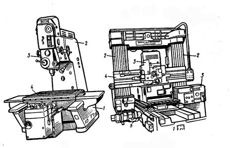
Fig.1. Coordinate boring machines:
a - single-column: 1 - bed, 2 - stand, 3 - boring head, 4 - table with sled;
b - two-column: 1 - bed, 2 - racks, 3 - boring heads, 4 - traverse, 5 - desktop
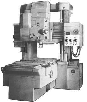
Single-column vertical jig boring machines are designed for machining holes with precise axes, the dimensions between which are given in a rectangular coordinate system.
In addition, the machine is also possible:
thread cutting;
Fine milling of surfaces with face or end mills;
trimming ends;
Marking and control of linear dimensions on parts.
The rotary tables supplied with the machines allow machining holes specified in the polar coordinate system, as well as mutually perpendicular and inclined holes and planes.
Under normal operating conditions, the machines provide an accuracy of center-to-center distances when processing in a rectangular coordinate system up to 0.06 mm.
The machines are equipped with a variety of tools and accessories for drilling and boring holes, threading, milling and marking:
ammo:
Collet with a set of collets,
drilling,
threaded,
Boring.
adapter sleeves for tools with Morse taper
arbors for cutters
set of boring bars
universal tool holder and tool holder with precise feed
microscope-center finder, mandrel-center finder
spring core
installation center
· a wide range of boring cutters, drills, reamers, cutters, taps.
Coordinate boring machine mod.2E450
Machine mod. 2E450A - single-column with table dimensions of 630x1120 mm, equipped with an optical measuring system with on-screen reading, a device for pre-setting coordinates, automatic stop of the table and sled in predetermined positions using a photoelectric null indicator. Length standards are flat glass line measures. The period of rotation of the spindle is carried out from an adjustable electric motor direct current through a three-speed gearbox. Within each stage, the spindle speed is adjusted steplessly within the range of 50-2500 rpm. The spindle feed is also infinitely variable via a friction variator. There is a mechanism automatic shutdown spindle feed at a given depth. Mechanical table clamps and manual clamping of the headstock are provided. The coordinate setting accuracy is 0.004 mm, the bored hole diameter accuracy is allowed no more than 0.005 mm.
Coordinate boring machine mod.2D450
Single-coordinate boring machine mod. 2D450 with the working surface of the table 630x1120 mm. equipped with optical devices that allow counting the integer and fractional parts of the coordinate size. The machine can be used both in tool and production shops for precise machining of parts without special equipment. Under normal operating conditions, the machine provides an accuracy of setting the center-to-center distances in a rectangular coordinate system of 0.004 mm. and in the polar system - 5 arc seconds. The accuracy of the distances between the axes of the holes, machined under normal conditions for coordinate boring, 0.006 mm.
Setting the axis of the hole on the product relative to the spindle axis to the required coordinate is carried out by the movement of the table or sled, the movement of which is controlled by a special optical device. The latter is based on precise rulers, fixed in one case on the table (movable ruler), in the other - on the frame (fixed ruler). The ruler of the table has 1000 high-precision divisions through 1 mm., the ruler of the bed - 630 divisions. Strokes are projected onto a matte screen at 75x magnification. To evaluate hundredths of one ruler interval in the screen plane, there is a scale with 100 divisions. To obtain a high-precision reading, there is an additional scale on the screen that allows reading up to 0.001 mm.

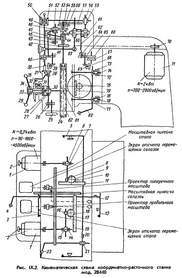
Rice. 2. Kinematic scheme of the machine mod. 2D450
Figure 2 shows the kinematic diagram of the machine mod. 2D450. The chain of the main movement determines the rotation of the spindle with the cutting tool, which is carried out from an adjustable DC motor 1 through a belt drive 2-3, shaft I, gears 6-7, shaft II, wheels or 7-10 to spindle III. The spindle speed changes steplessly by adjusting the electric motor 1 in the range of 700-2800 rpm. Switching speed stages of a two-stage gearbox is carried out by handwheel 11 through chain transmission 4-5. The speed is controlled by a tachogenerator mounted on shaft I.
The vertical supply of the sleeve, the spindle is carried out from a separate electric motor 17 DC with a wide range of regulation. Rotation through worm gear 18-19, splined shaft IV, gears 20-21, shaft V and worm pair 22-23, friction clutch with rail 25 of the spindle sleeve. Handles 40 with the clutch off, you can manually raise or lower the spindle sleeve. For more precise movements of the sleeve, there is a handwheel 41 connected to the shaft V by conical wheels 42-43. Automatic shutdown feeding of the spindle sleeve when the specified drilling depth is reached is carried out by turning off 17 with the microswitch.
The adjusting movement of the spindle head is made from asynchronous motor 12 through worm gear 13-14 and rack and pinion 15-16. The workpiece is moved in a rectangular coordinate system by moving the table in the longitudinal direction and the slide in the transverse direction from two independent DC motors 44 and 26 through similar worm gears 27-28 and 31-32, bevel gears 35-36 and 37-38, rack and pinion gears 29-30 and 33-34.
For fixing the table, sled and spindle head in necessary provisions unified clamps are used.
Table 1.
Model range of jig boring machines
| Model | Characteristics |
| 2A450 | Machine with an optical coordinate reference system along the X and Y axes |
| 2A450AF10, 2D450AF10 | Machine tools with an electronic reading and measuring system, including a digital display device, along the X and Y axes. Electronic flywheel mode. |
| 2L450AF11-01 | A machine with a digital indication device along the X, Y and Z axes and a preliminary set of coordinates along the X and Y axes. There is a tracking positioning mode and an electronic flywheel mode with a table movement resolution of 0.001 and 0.01 mm |
| 2E450AFZ0 | A machine tool with a CNC device, with the ability to set a processing program in an interactive mode along the X and Y axes and digital indication of coordinates along the Z axis. |
| 2L450AF4 | Machine with CNC, with contouring along the X, Y and Z axes. The graphic monitor allows you to debug programs without moving along the axes. Part programs can be prepared online with standard text files or automated systems. |
2. Calculation of criteria
2.1 Criteria for the development of technical objects
Among the parameters and indicators characterizing any technical object, there are always those that tend to change monotonously for a long time or tend to maintain at a certain level when their limit is reached. These indicators are recognized by everyone as a measure of perfection and progressiveness, and they have a strong influence on the development of individual classes of technical objects and technology as a whole.
Such parameters and indicators are called criteria for the development of technical objects. Their importance can be judged from the fact that technical progress in the field of any technical objects usually consists in improving some criteria without worsening (at least without significant worsening) others. When forming a system of development criteria, a number of conditions must be satisfied:
Measurability: only such parameter of a technical object can be taken as a development criterion, which allows the possibility of a quantitative assessment according to one of the measurement scales;
Comparability: the development criterion should have such a dimension that allows you to compare technical objects of different times and countries;
Exceptions: only such parameters of a technical object can be taken as development criteria, which primarily characterize its effectiveness and have a decisive influence;
Minimality and independence: the entire set of development criteria should contain only those criteria that cannot be logically derived from other criteria and cannot be their direct consequence.
Assessment of the technical level and quality of the product is carried out by comparative (comparative) analysis in the following order:
The base product is selected (ideal variant, analogue or prototype);
The numerical values of the main technical and economic indicators of the evaluated and base products are revealed:
The levels of relative indicators of the technical level and quality are calculated;
The value of the generalized indicators of the technical level and quality of products is calculated.
It should be noted that the main condition for comparing the estimated and base product- comparability of product elements, identity of functional purpose.
As a base product for comparison, the best, real sample of this type and standard size of products, available in world practice, is selected. It can be both domestic and foreign and is called an analogue. Sometimes, when solving problems for the modernization of products of this type, a prototype product is taken as a basic product, which is improved by eliminating existing shortcomings.
In some cases, equipment of the future can be taken as the basic product - an ideal option. Indicators characterizing the ideal variant in terms of technical level and quality are calculated based on the laws of development of technology of this type according to the development criteria.
When evaluating the technical level and quality of products, the values of the main dimensional parameter (capacity, working surface, useful volume, etc.) should not differ from those for the base product by more than 20%.
2.2 Calculation
Table 2.
Technical data of jig boring machines with table working surface 630x1120 mm
| Year of issue | Machine model | The largest diameter of drilling/boring, mm | Spindle reach, mm | The greatest distance from the end to the working surface of the table, mm | Spindle speed limits, rpm | power, kWt | Weight, kg | Dimensions | ||
| Length, mm | Width, mm | Height, mm | ||||||||
| 1 | 2 | 3 | 4 | 5 | 6 | 7 | 8 | 10 | 11 | 12 |
| 1968 | 2A450 | 30/250 | 710 | 750 | 50-2000 | 2,0 | 7800 | 2670 | 3305 | 2660 |
| 1973 | 2D450 | 30/250 | 710 | 800 | 50-2000 | 2,2 | 7800 | 3305 | 2705 | 2800 |
| 1978 | 2450A | 40/250 | 715 | 750 | 32-2000 | 6,3 | 7920 | 2430 | 2750 | 3400 |
| 1983 | 2E450AF1-1 | 30/250 | 710 | 770 | 10-2000 | 7,2 | 8500 | 2760 | 2765 | 3000 |
| 1990 | 2E450A | 30/250 | 710 | 770 | 10-2500 | 7,2 | 8050 | 3350 | 2500 | 2885 |
| 1992 | 2E450AF30 | 30/250 | 710 | 770 | 10-2500 | 7,2 | 8000 | 2760 | 2980 | 2980 |
Analyzing the presented data, it is possible to compile a nomenclature of criteria for the development of jig boring machines. Let us calculate the criteria under study, the calculation results of which are presented in Table 2.
1. Specific material consumption.
where: K m - specific material consumption. (kg / mm.)
M - mass (kg)
N is the value of the main parameter (mm).
2. Specific energy intensity.
where: E y - specific energy intensity (kW / m);
P - power (kW);
N is the value of the main parameter (m).
3. Specific area occupied by the machine.
where: S y – specific area occupied thus. (m 2 / m)
S - area occupied by the machine (m 2)
N - unit of the main parameter (m)
4. Unit of electric motor power per unit mass of the machine.
Table 3. Criteria for development.
Based on the data obtained from the development criteria, we will construct graphs, thanks to which it is possible to trace the trend in the change of criteria and make a forecast for 2007.
2.3 Determining the change of criteria
Specific energy intensity

Given the change in the values of the specific energy consumption of the machine, it is possible to trace the trend of increasing this parameter. Using the approximation method, it is possible to make a forecast for 2007, the value of the parameter will be 45 kW/m.
Specific material consumption

Using the trend approximation method, we find the criterion level in 2007. With a certain degree of probability, we can assert that the value of the criterion will be 32 kg/mm.
Unit of power per unit of mass

The resulting curve indicates an obvious increase in the unit of power per unit mass of the jig boring machine. Using the approximation method, we can assume possible meaning this parameter in 2007, which will be 1.42 W/kg.
Specific occupied area

Using the trend approximation method, we find the criterion level in 2007. With a certain degree of probability, we can say that the value of the criterion will decrease and amount to 30 m 2 /m.
3. Prospects for further development of jig-boring
machine tools
Workover modernization
Currently in Russian industry there is a large fleet of morally and physically obsolete jig boring machines of models 2A450, 2D450, 2E450 and their modifications. The age of these machines reaches 30-40 years, so their design solutions do not meet modern requirements for machines. In addition, the high wear of the units and the loss of accuracy parameters cause problems with their operation. All this requires the renewal of machine equipment, but most enterprises in the current economic environment do not have sufficient funds for this. Therefore, under these conditions, it is economically feasible to modernize existing equipment, as a result of which the consumer would receive a modern machine, the design of which would embody many years of experience in the production of machine tools that meets all the requirements for pointing (for this machine), equipped with modern components and control systems. At the same time, the customer, having handed over the machine for modernization, may not wait for the entire production cycle of the machine to be modernized, but to receive a modernized machine of this model (or a machine of another model) from the stock of machines available at the plant. In this case, the estimated cost of the handed over machine will be deducted from the price of the purchased machine.
The main components of the modernization of jig boring machines with manual control in the general case are:
· installation of an electronic reading and measuring system, which includes photoelectric converters of linear displacements of the LIR type and a digital indication device instead of optical reading devices;
· the use of a programmable controller to build a machine electric circuit instead of a relay control circuit;
· ball screws and adjustable high-torque DC electric motors in the drives of table and sled movements instead of rack and pinion gears, simple adjustable DC electric motors and worm gears;
installation of pneumo-clamps of the table and sled instead of electromechanical clamps;
· mechanization of movement of a spindle box;
· application of the sleeve displacement drive design with an adjustable DC motor.
Conclusion
In his term paper I developed a nomenclature of development criteria for jig boring machines with a table surface of 630x1120mm, taking as the main parameter largest diameter boring. I analyzed the dynamics of these criteria by years of production of machine tools. I found out due to what factors the change in the values of the criteria occurred. He gave a diagram of the machine, described its device, the principle of operation. He analyzed the dependence of specific indicators (specific energy consumption, material consumption) on the size of the machine.
He gave a forecast of the values of the criteria for 2007. The numerical values of the indicators are given in tabular and graphical form. I finished the work with a description of the prospects for the development of jig boring machines.
Bibliography:
1. Polovinkin A.I. Fundamentals of engineering creativity. - M: Mashinostroenie, 1988, -368s.
2. Belik V.G. The technical level of machines and devices: ways to improve it. - Kyiv, Technique, 1991.-200s.
3. Mogunov V.I. Metal cutting machines. Quick Reference. - M.: Gosinti, 1964. -505s.
4. Nomenclature reference book. Universal metal-cutting machines manufactured by the enterprises of the Minstankoprom in 1978-1979 - M .: NIIMASH, 1968. - 219p.
5. Metal cutting machines. Directory directory. Part 3 - Machine tools of the drilling and boring group - M .: NIIMASH, 1973.
6. Metal cutting machines. Directory directory. Part 2 - Machine tools of the drilling and boring group. - M.: NIIMASH, 1965.
7. Metal cutting machines. Ed. V.E. Pusha.-M.: Mashinostroenie, 1986. -571s.
8. USSR Minstankoprom. Universal metalworking machines manufactured by the enterprises of the Minstankoprom in 1973-1974. Nomenclature reference book. - M.: NIIMASH, 1973. -173p.
9. USSR Minstankoprom. Universal metalworking machines manufactured by the enterprises of the Minstankoprom in 1970. Nomenclature reference book. - M.: NIIMASH, 1970.- 123p.
10. Metal-cutting machines. Nomenclature catalog. Part 1. 1992-1993 - M.: ENIMS, VNIITEMR, 1992.
11. Metal cutting machines. Nomenclature catalog. Part 1. 1990-1991 - M.: VNIITEMR, 1990.
12. Metal cutting machines. Ed. N.S. Koleva.-M.: Engineering, 1980.-500s.
13. Smirnov A.I. Perspectives of engineering technology. -M.: 1992
14. Smirnov V.K. Turner-borer: Proc. For SPTU. – 5th ed., revised. and additional - M .: Higher. school, 1987. - 255 p.
TO jig boring machine 2455AF10
In addition to processing holes on the machine, it is possible to produce semi-finishing and finishing milling of planes and curly contours.
The machine is not only a machine for precise processing of various products, but also a measuring machine that allows accurate measurements in a rectangular coordinate system. In the presence of a flat or universal rotary table, precise measurements of the angular coordinates are also possible.
High precision and rigidity of the machine, small temperature deformations and convenient control allow for high-precision processing of products and use it in various industries industry.
On the upgraded machine, the optical reference system was replaced with a reference system "digital indication" of the movements of the table, headstock and spindle sleeve with a resolution of 0.001 mm, which allows the machine to be used as an accurate measuring machine for marking work, checking linear dimensions and center distances.
Using the rotary table supplied with the machine, it is possible to machine holes and planes located at different angles to each other.
2455A F10
TO jig boring machine 2A450AF10
A single-column vertical jig boring machine is designed for machining holes with an exact arrangement of axes, the dimensions between which are given in a rectangular coordinate system.
Along with boring, drilling, fine milling, marking and control of linear dimensions, in particular center-to-center distances, can be performed on the machine.
Using rotary tables, it is possible to process holes specified in the polar coordinate system, inclined and mutually perpendicular holes, and turning end planes. structurally different in that:
table clamp, sled ( X, Y ) and the headstock is driven by pneumatics;
the movement of the spindle head is carried out from el. engine.
Using the rotary table supplied with the machine, it is possible to machine holes and planes located at different angles to each other.
Main technical characteristics of machine tool model 2D450A F10
TO jig boring machine 2A459AF4
CNC horizontal jig boring machine with a rotating table.
The machine is designed to perform boring and milling operations with high accuracy and productivity, as well as reaming, countersinking, reaming, trimming ends, tapping threads, performed according to a given program. The machine has the ability to work in manual mode "Digital indication".
The scope of the machine is single, small-scale, mass production of high-precision parts in tool and mechanical shops of machine-building plants.
The characteristic feature of the machine is hole making located on the same axis, on parallel, perpendicular or located at arbitrary angles, parallel to the mirror of the table axes with high accuracy both in geometry and in their relative position.
Main technical characteristics of machine tool model 2A459A F4
TO jig boring machine 2E440AF10

Vertical single-coordinate boring machine. Designed for processing holes in conductors, fixtures and parts, when it is necessary to achieve high accuracy in the relative position of the holes being machined.
On the machine, you can also carry out marking and verification of linear dimensions and center-to-center distances. The presence of a mechanical movement of the table and sled allows you to perform light milling work on the machine.
The machine is equipped with an electronic reading and measuring system of the “Digital indication” type, frequency drives of feeds and the main movement, complete with asynchronous motors.
Main technical characteristics of machine tool model 2E440A F10
TO jig boring machine 2V440AF4
The main differences from the coordinate boring machine mod. 2E440AF10 are: larger size table, increased movement of the table and sled, internal spindle taper - (spec. 5°) .
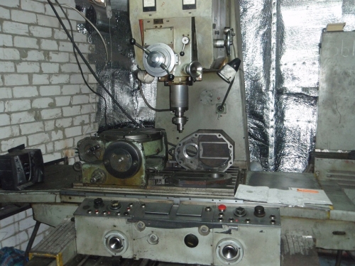
In various fields production activities equipment such as a jig boring machine is often used. This equipment is most often used in metallurgical, machine-building industries. The main purpose of this group of machines is metal surface treatment, performing such operations with workpieces as boring, punching holes, countersinking and many other operations.
Device jig boring machine
In fact, a jig boring machine performs absolutely all the functions that conventional machines do, but its advantage is that such equipment performs all actions with a high degree of accuracy. Such accuracy of processing parts by the machine is achieved by the fact that this equipment is equipped with all kinds of elements of an optical, mechanical and automatic nature.
Details on a jig boring machine can be processed both serial and single, it depends on the type of enterprise where this equipment operates.
The main working element of this equipment, as in other lathes, is the spindle, which can be located in the machine, both in a horizontal and vertical position. On the spindle itself, all kinds of tools are already additionally attached, with which the work will be carried out. For example, such working elements can be a cutting boring bar, countersinks, drills and milling equipment.
To date, the most common are such jig boring machines that carry out work by means of numerical program control, this equipment allows you to perform all work with high accuracy and minimizes the cost of personnel servicing the machine.
Types of jig boring machine
Coordinate boring machines are classified into single-column and double-column machines. The principle of operation of these machines is similar and is as follows. The workpiece for its subsequent processing is fixed on a table, which is performed in a coordinate-plane manner to achieve the greatest accuracy in processing the part. The tool itself, necessary for specific types of work, is fixed on the spindle element. The spindle itself is set using the coordinates of the table, for precise contact with the workpiece during processing. To do this, the table is moved until it is installed exactly as the job requires.
The main advantages of using jig boring machines are that they are equipped with special corrective devices that allow minimizing errors when processing workpieces. The coordinates themselves are read automatically, by means of an optical device, which measures the necessary values for setting the workpiece.
Characteristics of jig boring machine
This equipment has excellent vibration resistance characteristics, which makes it safe to work on such equipment. Besides this characteristic directly affects the accuracy with which the equipment will work.
The main working unit of this equipment includes such elements as racks, a traverse, the boring head itself, a spindle device, and a work table. All equipment is mounted on a solid steel frame, which is a stable platform with a large mass, which ensures its immobility during work.
The jig boring machine is an equipment high level besides, it is versatile in operation. The machine is also capable of performing such work as surface milling, as well as the machine can be used for cutting ends and marking the workpiece. Thus, having this equipment, you can avoid additional costs for the purchase of auxiliary working tools, since this machine performs a variety of functions.
Information about the manufacturer of the jig boring machine 2V440A
Manufacturer of jig boring machine 2B440A Kuibyshev Plant of Coordinate Boring Machines, Stan-Samara CJSC founded in 1963.
The history of the Kuibyshev plant of coordinate boring machines dates back to 1963, when the first stage of this enterprise was commissioned. The young team of the plant in a short time mastered the production of high-precision machine tools and already in 1966 produced several hundred of them.
The plant ceased to exist in 1991, and its production areas several machine-tool enterprises have been opened, which continue to produce jig boring machines, are engaged in their repair and modernization. Plant of jig boring machines "Stan-Samara" CJSC, Samara Research and Production Enterprise of jig boring machines, CJSC, "Stankoservis" LLC, etc.
Coordinate boring machines. General information
Synonyms: jig boring machine, jig boring machine.
Jig boring machines are designed for processing holes in conductors, fixtures and parts that require high precision. relative position holes (within 0.005 - 0.001 mm), without the use of tools for guiding the tool.
These machines can be used for boring, drilling, countersinking and reaming of holes, fine milling of ends, measurement and control of parts, as well as marking work.
Machines can be used for processing holes in conductors, fixtures and parts that require high accuracy in the relative position of the holes. Along with boring, marking and checking of linear dimensions, in particular center-to-center distances, can be performed on machines. Using the rotary tables and other accessories supplied with the machine, it is also possible to machine holes specified in the polar coordinate system, inclined and mutually perpendicular holes and machine end surfaces.
Coordinate boring machines are designed for processing holes with the exact location of their axes without the use of markings. The accuracy of the location of the holes is achieved on these machines in the range of 0.005-0.001 mm. These machines can be used for drilling, reaming, countersinking, boring holes and surface milling (milling is rarely performed). Coordinate boring machines are also used for measuring and controlling parts, for precise marking work.
Coordinate boring machines are more often used in tool and experimental shops.
Coordinate boring machines are single and double-column.
Single-column machines have a cross table designed to move the workpiece in two mutually perpendicular directions.
Two-column machines have a table located on the guides of the bed. The table moves the workpiece placed on it only in the direction of the x-coordinate. Racks are located on both sides of the bed, a cross member is placed on them, on the guides of which there is a spindle head. When the headstock moves along the guides of the crossbar, the spindle axis moves relative to the product installed on the table in the direction of the second coordinate y. To raise or lower the headstock, the crossbar is moved up or down along the rack guides. In all types of jig boring machines, holes are machined with a vertical spindle feed with a fixed spindle head and table.
In order to obtain a more accurate distance between the centers of the holes, jig boring machines should be installed in separate rooms, in which it is always necessary to maintain a constant temperature of +20 ° C with a deviation of no more than ± 1 °.
The measurement of the distance between the axes of the holes can be carried out using:
- rigid and adjustable limit measures used in combination with indicator devices
- precision lead screws with limbs and verniers
- accurate scales in combination with optical instruments
- inductive feedthrough screw sensors
According to the first method measured with a set of gauge blocks and a gauge. They are located between a movable stop mounted on a table and an indicator pin mounted on a fixed stand.
According to the second method measured with precision-made lead screws, which are designed to move the table and other parts. The amount of movement is counted by a limb with a vernier. To eliminate lead screw errors, correction rulers are often used, which, through a lever system, produce additional movement of the table.
The measurement is counted according to the third method on a very precise scale observed through a microscope. The scale is a mirror steel shaft with a thin helical risk applied on its surface with a step t = 2 mm or in the form of a flat mirror scale. The advantage of this measurement method is that there is no wear on the mirror shaft or mirror scale, which are not used to move the table.
Fourth measurement method using inductive screw probes provides the possibility of remote less tiring observation of the arrow and the scale of the electric indicator.
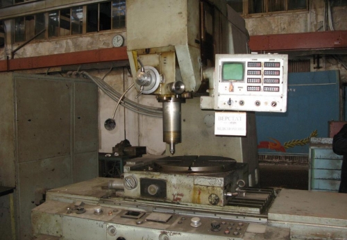
2V440A Coordinate boring machine. Purpose and scope
The machine is designed for processing holes in conductors, fixtures and parts with the exact location of the axes, the dimensions between which are given in a rectangular coordinate system.
Along with boring, drilling, light (fine) milling, marking and checking linear dimensions, in particular, center-to-center distances, can be performed on the machine. The machine is equipped with rotary tables, which makes it possible to process holes specified in the polar coordinate system, inclined and mutually perpendicular holes and turning end planes.
The machine can drill holes up to 40 mm in diameter, mark precise templates, check linear dimensions and center-to-center distances, as well as perform light milling work, for which mechanical feed of the table and sled is provided.
In terms of its layout, this machine belongs to single-coordinate boring machines with a cross table, with a spindle head moving along the vertical guides of the L-shaped rack.
Machine 2V440A has a rectangular table with longitudinal and transverse movement. The adjusting movement of the spindle head is provided.
The working and accelerated movement of the table is carried out independently in the longitudinal and transverse directions by asynchronous electric drives with a wide range of regulation.
Spindle feeds are infinitely variable with a friction variator. There is a mechanism for automatic shutdown of the spindle feed at a given depth.
The machine is used for work in tool shops (processing of conductors and fixtures) and in production shops for precise processing of parts without special equipment.
Precise setting of the table to a given coordinate is done manually, with a handwheel.
Using the rotary tables and other accessories supplied with the machine, it is possible to machine holes specified in the polar coordinate system, inclined and mutually perpendicular holes, and turning end planes.
The machine has a number of accessories that facilitate the work (center finders, tool holders, etc.) and a horizontal rotary table.
The machine is equipped with a universal rotary table, which makes it possible to process holes, the axes of which are set in the polar coordinate system, with the reading of the angles along the limbs, to divide with the help of dividing disks; machine inclined holes.
The machine is equipped with an optical measuring device with flat glass line measures and screen optics with helical micrometer.
The drive of the main movement - from the regulated electric motor of a direct current. The speeds are regulated according to the g - e system (generator - engine, Leonard system) in the range of 4: 1.
To shift the speed range given by the variable speed motor, use simple box speeds.
The headstock of the machine has only an adjusting movement. To move the sleeve, a connected drive with a stepless change in feeds is used. To drive the movements of the table and sled, DC electric motors with stepless speed control from the EMU, to which they are connected in series, are used.
In this machine, the table and sled drive is not designed to automate precise coordinate settings, since it does not provide the necessary low table and sled movement speeds for this.
The machine is used in tool, machine-building and instrument-making shops for processing workpieces for parts of single and serial production.
The working and accelerated movement of the table is carried out independently in the longitudinal and transverse directions by asynchronous electric drives with a wide range of regulation, which make it possible to increase the rigidity and productivity of the machine during milling.
Precise setting of the table to a given coordinate is done manually, with a handwheel. The machine is equipped with a digital indication device, enabling the operator to set coordinates with a resolution of 0.001 mm in two mutually perpendicular directions.
The spindle is rotated from controlled electric drive alternating current through a three-speed gearbox. Spindle feeds are infinitely variable with a friction variator. There is a mechanism for automatic shutdown of the spindle feed at a given depth.
The machine is provided with clamps for the table, sled and spindle headstock.
Machine accuracy class A according to GOST 8-71.
Description of the machine
The base of the machine is a box-shaped bed with internal stiffeners. The slide moves along the rolling guides of the bed in the transverse direction, along the rolling guides of which the table moves in the longitudinal direction.
The fixing of the table and the slide in the working position is carried out by handles, which block the working feeds with the help of limit switches. The automatic feed cut-off also occurs in extreme positions tables and sleds.
A cast rack is installed on the frame, on which the gearbox is mounted.
A spindle box balanced by a counterweight moves along the vertical guides of the rack. The counterweight is located in the rack and is connected to the spindle box by cables.
The spindle box contains a boring spindle, an axial feed mechanism, a device for cutting off the feed at a given depth, and a fine adjustment mechanism. manual feed.
The machine has a device for working with cooling.
Main accessories of the machine
The machine accessories include: point finders, fine feed tool post, universal tool post, adapter sleeves, collet holder, drill chuck, spring core, setting center, indicator holder, holder for sharpening small drills and cutters, boring bars, cutting tools, rotary tables.
Center finder with indicator consists of a guide plate 1 with a tapered shank for fixing in the spindle and a housing 2, on which the indicator 3 and the contact lever 4 are fixed. The spring 5 creates a force with which the contact lever is pressed against the surface to be checked. The body moves along the length of the bar and is fixed in any place depending on the radius at which the test takes place.
The center finder is applied:
- to align the axis of the hole or the axis of the cylindrical protrusion on the product with the axis of the spindle
- checking the parallelism of any plane of the product to the plane of the table (perpendicular to the plane of the product of the spindle axis)
- checking the parallelism of any vertical plane of the product to the movement of the table in the longitudinal or transverse directions
Center Finder Microscope installed in the spindle taper.
To set the edge of the product along the axis of the spindle, the sighting square attached to the microscope is used, which is applied to the base edge of the product. On the polished horizontal plane of the square, a line is applied that exactly coincides with the vertical reference plane, i.e. the base edge of the product. When reconciling the product, the risk must be between the horizontal or vertical lines of the double cross.
Mandrel-center finder used to set the edge or convex cylindrical surface of the product at a certain distance from the spindle axis. A washer 1 with a diameter of 20 mm is pressed against the lower end of the mandrel by a spring. With pin 2, the washer has a radial clearance, due to which it can be displaced relative to the precise neck 3 of the mandrel. The cylindrical neck of the mandrel has no radial runout, and its diameter is equal to the diameter of the washer. If the edge of the product touches the washer at a distance of exactly 10 mm, then when the spindle is rotated, the washer will rotate without beating relative to the neck of the mandrel. At the slightest displacement of the edge, a noticeable beating of the washer will appear. The installation accuracy reaches 0.005 mm.
Spring core designed for marking on the machine. The core head is retracted inside when the knurled sleeve is turned. At the end of the rotation of the same sleeve, the striker is released and, under the action of a spring, strikes. The top of the core should be located above the marked surface at a distance of 5.5 mm.
Turntables– horizontal and universal are supplied with the machine as special equipment. The devices of the dividing mechanisms of the tables are the same and, from the point of view of kinematics, are similar to universal dividing heads. Tables differ from each other in size and availability. universal table turntable tilting devices
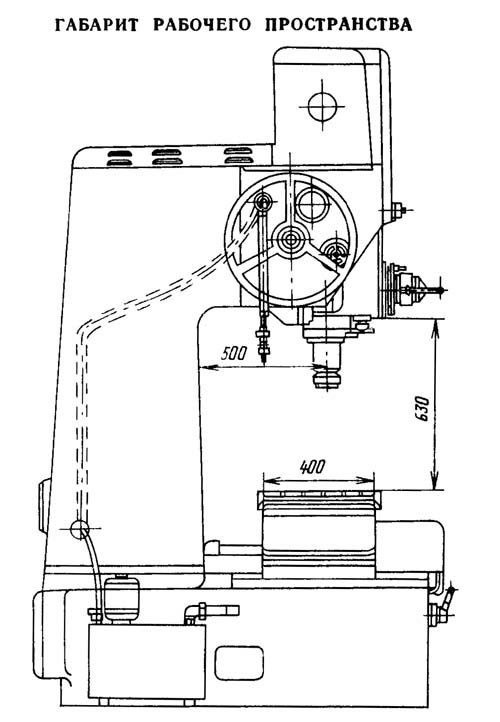
2V440A Dimensions of the working space of the jig boring machine
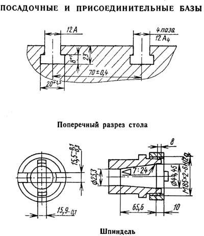
2V440A Landing and connecting bases of a coordinate boring machine
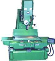
2V440A General view of the jig boring machine

2V440A Location of machine controls
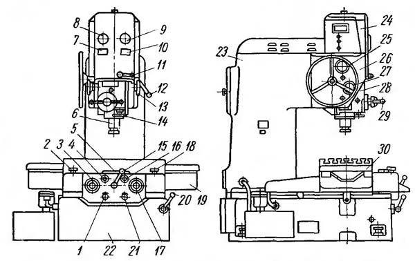
List of machine controls 2V440A
- handwheel for zeroing the transverse scale
- skid speed controller
- handwheel manual movement skid
- fungus spiral micrometer transverse scale
- screens and control buttons
- spindle
- speed indicator
- ammeter
- spindle speed tachometer
- spindle feed rate indicator
- handle for turning off and reversing the spindle feed
- handle for fixing the spindle box
- spindle feed adjustment handwheel
- spindle manual feed handwheel
- table fixing handle
- longitudinal scale spiral micrometer fungus
- handwheel for manual movement of the table
- table speed controller
- sled
- sled fixing handle
- handwheel for zeroing the longitudinal scale
- bed
- rack
- gearbox
- spindle box movement handwheel
- guide block
- handwheel for switching speed stages
- spindle box
- handles for raising and lowering the spindle sleeve
2V440A Kinematic diagram of the machine
The base of the machine is the frame 22 (Fig. IX.1) box-shaped with internal stiffeners. Slides 19 move along the guides of the frame in the transverse direction, which have the same guides in the upper part, perpendicular to the guides of the frame. Table 30 moves along the slide guides.
The table and sled move along rolling guides with rollers enclosed in metal cages. The shape of the guides of both the table and the sled is the same - one of the guides is V-shaped, the second is flat.
The table is moved by a DC electric motor 1 (Fig. IX.2, N - 0.24 kW, n = 3600 rpm with adjustable speed, through a double worm gear 14, 15, 16, 17, a rack and pinion gear 18 and rail 19 fixed on the machine table.
The drive for moving the sled 6, 7, 8, 9, 10 and 11 is similar to the drive for moving the table, with the only difference that the drive gearbox mounted on the sled moves with them relative to the rail 11 fixed on the frame
By rotating the handwheels 2, located on the shafts of the electric motors 1 and displayed on the front wall of the control panel 3, 17 (Fig. IX, 1), you can manually accurately set the coordinates. The number of revolutions of each of the electric motors 1 (Fig. IX.2) is adjustable in the range of 50: 1, which makes it possible to quickly move the table at a speed of 800 mm / min, mill planes and make installation movements at a speed of 16-320 mm / min.
The table is fixed by turning the handle 4; in this case, the end of the shaft, ending with a thread, unscrews from the nut 12 and creates a spacer force between the clamps 3 and 13.
The slide is fixed in the same way, but the rotation of the handle 23 is transmitted to the screw through the helical gears 21. The screw, unscrewing from the nut 20, creates a spacer force between the clamps 5 and 22.
The accuracy of the center distances of the machined holes, the correctness of their geometric shape and the cleanliness of processing largely depend on the design of the spindle assembly. In this machine, the radial bearings of the spindle 5 (Fig. IX.3) are single-row roller bearings 3 and 4; bearing 4 is assembled with a slight preload (3 - 6 microns), and the upper bearing 3 is assembled with a small gap or preload (±2 microns). Axial loads are perceived by thrust ball bearings 2. The spindle 5 is locked with a nut 1 and is connected to the main drive drive by a connecting toothed (splined) shaft 1 (Fig. IX.4), the upper end of which enters the toothed hole of the hollow shaft 54 (Fig. IX.2 and IX.4), and the lower one - into the upper notched (slotted) hole. Such a connection unloads the spindle from radial forces that may arise due to misalignment of the spindle and shaft 54 (Fig. IX.4) of the gearbox, since shaft 1 mates with them with some gaps on surfaces of small length. The total length of the spindle is smaller, and its upper end does not go beyond the dimensions of the gearbox.
The boring spindle 5 (Fig. IX.3) is driven by a continuously variable DC motor 71 (Fig. IX.2) (N = 2 kW, n = 700 ... 2800 rpm) through a V-belt transmission 70 and 42 and three-speed gearbox (Fig. IX.2 and IX.4).
The first - the lowest - speed stage of the spindle is obtained with the following gear: driven pulley 42 of the drive, gears 44, 45, 52 and 53. To obtain the second - middle - stage speeds, the gears 52 and 53 are disengaged, and the wheels 48 and 56 are engaged. Gears 53 and 56 transmit rotation to the spindle through a toothed (splined) shaft. To obtain the third - highest - speed level, the pulley 42 is connected to the spindle using a cam clutch 46 and a splined shaft 54 (Fig. IX.2 and 4); gear wheels 48. 52, 53 and 56 are not involved in the work. Within each of these three stages, the spindle speed changes steplessly due to the smooth regulation of the speed of the electric motor 71 in the range of 4:1.
The gears are switched by levers, which at one end enter the grooves of the control drum 47 (Fig. IX.2), which is turned by the handwheel 38 through the bevel 39 and cylindrical 41 gears. Simultaneously with the rotation of the drum 47, the disk 40 rotates, on which numbers are applied indicating the ranges of revolutions corresponding to each stage of the gearbox.
The feed movement is carried out according to the following chain: the gear wheel 55 (Fig. IX.2 and IX.4) rotates together with the hollow shaft 54 and drives the wheel 57, on the shaft of which sit the driving cones of the sliding pulley 60 of the continuously variable transmission. The driven cones corresponding to them receive rotation through the steel ring 61.
Using the handwheel 68 (Fig. IX.2) through the bevel gears 69 and the cylindrical wheel 65 rotate the gear nut 64 (Fig. IX.2 and IX.4) and thereby move in the axial direction the thrust 62 associated with the upper drive and lower driven cones continuously variable transmission. Therefore, it is possible either to bring the driving cones together and simultaneously push the driven cones apart, thus increasing the speed of rotation of the worm 59, or, conversely, push the driving cones apart and bring the driven cones together, thereby reducing the number of revolutions of the worm. This makes it possible to change the amount of feed per revolution of the spindle steplessly.
The feed rate is set by the drum 67 (Fig. IX.2), which rotates simultaneously with the rotation of the handwheel 68 through gears 65 and 66.
On the shaft of the worm wheel 58 (Fig. IX.2 and IX.4), which is driven by the worm 59, two bevel wheels 51 (Fig. IX.2) are freely installed, constantly engaged with the bevel wheel 49. Switching the clutch 50 gives the right or left rotation of the worm 28. Thus, the spindle can be fed both down and up.
The worm wheel 27 is loosely seated on the shaft of the rack and pinion gear 81, which is in constant engagement with the rack 82 of the sleeve 24 (Fig. IX.2 and IX.3) of the spindle. The worm wheel 27 is connected to the shaft of the gear wheel 81 using a clutch mounted inside the worm wheel 27, which is activated by means of a double handle 29 mounted on the shaft of the gear wheel 81. When the clutch is off, the rack and pinion gear wheel 81 can be directly rotated, quickly raising or lowering the sleeve 24 of the spindle.
Manual fine feed is performed by handwheel 25 through gear wheels 26.
To automatically turn off the working feed upon reaching a predetermined processing depth set on the limb 34, the cam 35 disengages the gear wheel 36 from the gear wheel 37.
Disconnection occurs when the zero of the limb coincides with the zero of the vernier; for this, the limb is fixed in a position in which the division indicating the length of the given stroke of the sleeve coincides with the zero of the vernier. The accuracy of the resulting size along the length is 0.2-0.3 mm.
In order for the limb 34 to make only one revolution during the full stroke of the spindle sleeve, there is a reduction gear between the rack and pinion shaft 81 and the limb, made up of gears 30, 31, 32 and 33.
The set spindle speed is indicated by a tachometer, which is driven through gears 55 and 57 (Fig. IX.2 and IX.4) and helical gears 63 (Fig. IX.2).
From the intermediate shaft through the cylindrical gears 43, the gear lubrication pump receives rotation.
The spindle box is moved manually along the vertical guides by means of the handwheel 25 (Fig. IX.1) through the worm gear, bevel wheels, rack and pinion gear 75 (Fig. IX.2) and the rail 79, which is fixed on the body of the spindle box.
The spindle box 28 (Fig. IX.1) is fixed on prismatic guides with the help of clamps, which, by means of rods and screws 74, 78 (Fig. IX.2), receive movement from the handle 80 through gear wheels 72 and 76 and gear wheels - nuts 73 and 77.
2V440A Optical reference system of machine coordinates

Optical device of the machine. The magnitude of the coordinate displacements is measured using precise glass scales and an optical device that allows projecting with a large increase in the image of scratches and numbers on the scale scale, as well as the grid of the spiral micrometer on the screen.
The optical device of the machine consists of two movement counting schemes: a table - in the longitudinal direction and a slide - in the transverse direction.
In the scheme of counting displacements in the longitudinal direction, the scale ruler of the table (see Fig. IX.2) is movable, which is associated with it and moves with it relative to the optical system. In the scheme of counting displacements in the transverse direction, the optical system moves relative to the fixed scale bar of the sled, which is fixed on the frame.
Both optical schemes are the same, and only for the convenience of layout, prisms and mirrors that change the course of rays are included in the optical scheme of the transverse scale. Therefore, only the optical scheme for counting table movements is considered below (Fig. IX.5, a).
From the light bulb 1, through the collector 2 and the condenser 3, the rays condense in the plane of the strokes of the scale bar 5. The ruler 4 has no scratches and serves to protect the plane of the strokes of the scale bar from dust.
The rays pass through a glass scale bar 5 with dividing risks and numbers printed on it; passing through the lens 6 and the plane-parallel plate 7, they give in the plane of the grid of the spiral ocular micrometer 8 an image of marks and numbers with a fivefold increase.
Passing through the projection eyepiece 9 and safety glass 10 and reflected from the flat mirrors 11 and 13, the image of the scale bar marks is projected onto the screen 12 with a magnification of 60x. The fractional part of the size is estimated on the screen using a grid projected on it • a spiral micrometer (Fig. IX.5, b). Reading price 1 mk.
To make corrections to the reading on the screen, to compensate for the inaccuracy of divisions of the scale bars and to eliminate the accumulated error, the optical reading system of the machine has a correction device.
Correction is carried out by turning the plane-parallel plate 7 (Fig. IX.5, a) around the horizontal axis; in this case, the images of the strokes of the scale bar are shifted in the field of view of the screen by the required amount.
The plate, installed in the course of the rays of the optical device, rotates through the lever system from the correction ruler, fixed on the table (or frame). The correction ruler allows you to correct both accumulated and local errors in scale bar divisions 5. To correct accumulated errors, the correction ruler is set at an angle. Correction of local errors is provided by the appropriate ruler profile curve.
A shift of the stroke image on the screen by 0.001 mm corresponds to lowering or raising the lever on the correction ruler by 0.2 mm.
Spiral micrometer 8 has two grids - movable and fixed (Fig. IX.5, b). A double Archimedean spiral is applied on the movable grid, the pitch of which is 0.5 mm; this corresponds to 0.1 mm scale scale 5 (Fig. IX.5, a), the image of which is built in the plane of the grid with a fivefold increase.
In the center of the moving grid (Fig. IX.5, b) there is a circular scale with 100 divisions, which are digitized every five divisions. The movable grid rotates relative to the fixed one, on which the index with an arrow is applied. The index is divided into 10 divisions (Fig. IX.5, c), each of which is equal to the pitch of the spiral applied to the moving grid.
The divisions of the index are digitized and, when the circular scale is set to zero against the arrow, they are in the middle of the corresponding turn of the spiral. With a full turn of the movable grid, the spiral is shifted relative to the fixed index by a step, i.e. by 0.1 mm. The linear movement of the spiral by one step corresponds to a full turn of the dial. Therefore, the price of its division \u003d 0.1 mm * 1/100 \u003d 0.001 mm \u003d 1 micron. Thus, the circular scale is "micron" and serves to read hundredths and thousandths of a millimeter.
When setting the stroke of hundredths and thousandths against the arrow, the spiral is shifted by the same amount relative to the index divisions. When the table (sled) is moved, the digitized millimeter strokes of the scale bar move along the index.
The movable mesh (Fig. IX.5, b) is embedded in a frame, the rotation of which is communicated through a system of gears from the fungus 16 (Fig. IX.1).
For the convenience of counting the coordinates, it is taken as the initial position at which the center of the base hole of the product fixed on the table is aligned with the spindle axis. Wherein:
- rotating the fungus 16, set the zero of the circular scale against the target arrow
- by rotating the handwheel 21, set the image of the nearest millimeter stroke in the middle of the spiral, indicated by zero; the screen will look like the one shown in Fig. IX.5, in
- the same setting is made on the screen of transverse coordinates, for which the fungus 4 is rotated (Fig. IX.1), and then the handwheel 1
- adding to the initial readings or subtracting from them (depending on the direction of movement) the given dimensions, determine the installation coordinates for the longitudinal and transverse movements
- rotating the fungus 16 (respectively, the fungus 4), set the hundredths and thousandths of the fractional part of the size on a circular scale
- move the table (sled) to a position where the digitized millimeter stroke of the scale scale 5 (Fig. IX.5, c) will be aligned with the middle of the spiral, indicated by the number of tenths of the fractional part of the size being set.
The view of the screens with the set dimensions is shown in fig. IX.5, in
In this way, full size consists of whole millimeters - digitization of the stroke of the scale bar, tenths of a millimeter - digitization of the spiral, hundredths and thousandths of a millimeter - readings of the circular scale.
2V440A Electrical circuit diagram of the machine

- Electric motors:
- D - spindle drive
- SL - skid
- ST - table
- D1 - generator
- D2 - cooling
- D3 - movement of the slider of the regulator
- D4 - EMU electric motor
- 1 - generator
- Contactors:
- 1K - electric motors D1, D2, D4
- ЗК, 4К - step-by-step start of the electric motor of the electric motor D
- 5K - braking motor D
- 1KB - stroke "to the right" of the electric motor CT
- 1KH - stroke "to the left" of the electric motor CT
- 2KB - "Forward" stroke of the electric motor SL
- 2KN - stroke "Back" of the electric motor SL
- Buttons:
- 1KU, 2KU - stop and start the electric motor D
- ZKU, 4KU, 5KU, 6KU - stopping and braking, starting, accelerating, decelerating the electric motor D
- 7KU - illumination optics milling speed setting
- 8KU - slow spindle rotation
- Stroke limit switches:
- BK1 - spindle
- VK3, VK4, - tables to the right, to the left; VK6, VK7 - forward, backward
- VK8, VK9 Limit switches for blocking: slide - angle of rotation of the regulator
- BK2, BK5 - clamp table sled
- Switches:
- BB - introductory
- VO - local lighting
- Lamps:
- 1LS, 2LS - signal
- 1LO, 2LO - lighting
- 1L, 2L - lighting optics
- LSh - illumination scale slide
- Intermediate relays for boosting the speed of electric motors: 1RP - ST; 2RP - SL
- 3RP - intermediate relay for switching on the lighting of the optics;
- 4PT1 - spindle slow rotation relay
- Time relay: 1РВ - step start of the electric motor D; 2РВ - lighting optics
- 1RT, 2RT - thermal motor protection relays
- 1PP, 2PP, ZPP, 4PP - fuses
- 1С10-5С10 - adjusting resistances
- 1ST - starting-braking resistance of the electric motor D
- OVG, OVD, OVST, OVSL - shunt windings of the generator and electric motors L, ST, SL
- SOG, SOD, OVS - serial windings of the generator and electric motors D and D3
- ShR - motor excitation regulator D
- C - stabilizing capacitor
- 1TP, 2TP - step-down transformers
- 1PO, 2PO - speed controllers for ST and SL engines
- 1B, 2B - voltmeters (they have a graduation of the speed of movement of the table and sled)
- OU-1 and OU-11 - EMU control windings
- SV - selenium rectifier
- AT - excitation regulator autotransformer ShR
- KO - compensation winding EMU
- ShKO - EMU compensation winding shunt
- 1SD, 2SD, ZSD, SDV - additional resistances
2V440A Schematic diagram
The electrical circuit of the machine includes electric drives: spindle, table and sled of the cooling system, and in addition, provides illumination of the optics of the machine, blocking and protection in various modes of operation of individual units.
The rotation of the boring spindle, the movement of the table and the slide are made from DC motors, and the cooling pump is driven by an asynchronous motor.
To power the spindle drive motor, there is a generator-motor, and for table and sled motors, an electric machine amplifier.
Machine voltage supplied by a package switch BB; at the same time, the dial of the gearbox is illuminated with lamps 1LS and 2LS.
The voltage to the excitation windings of the electric motor D and the generator G is supplied from the selenium rectifier CB, to the excitation windings of the motors ST and SL from the generator G.
Turning on the generator and EMU. When the 2KU button ("Generator") is pressed, the 1K contactor is turned on, which starts the electric motors: D1 - generator drive; D4 - electric machine amplifier; D2 - cooling systems (when the 1РШ socket is on).
Spindle drive. The electrical circuit provides the inclusion of rotation, its deactivation with and without braking, stepless change in the number of revolutions, as well as slow rotation with a "creeping" speed.
First stage spindle start. When the 4KU button (“Spindle Start”) is pressed, the ZK contactor connects the spindle rotation motor D to the generator through the 1ST start-brake resistance.
Second stage spindle start. Simultaneously with pressing the 4KU button, it receives power from the 1РВ time relay and, with a time delay, turns on the 4K contactor, which turns off the time relay and shunts the 1ST resistance.
Slow spindle rotation. The 8KU button (“Spindle slowly”) turns on the slow rotation of the engine (40-60 rpm) to obtain a “creeping” spindle speed, at which the product is aligned using a center finder. At the same time, the 4RP relay is turned on, the excitation winding of the ATS engine is connected to full voltage, and the excitation winding of the OVG generator is connected through the resistance 1SD. To eliminate speed fluctuations, the serial winding of the SOG generator is shunted.
Changing the spindle speed. The number of revolutions of the electric motor D within pp \u003d 700; nmax = 2800 rpm is regulated by a shunt regulator; by pressing the 5KU (“Fast”) or 6KU (“Slow”) button, the collector alternating current motor Dz is turned on in one direction or another, which, by moving the slider of the ShR regulator, introduces more or less resistance into the excitation winding of the ATS of the spindle motor.
Limit switches VK8 and VK9 limit the angle of rotation of the regulator in the extreme positions, turning off the motor D3.
Spindle braking. When the ZKU button is fully pressed, the 5K contactor is turned on and at the same time the ZK and 4K contactors are turned off.
With the ZK contacts, the armature of the motor D is disconnected from the power supply, and with the 5K contact, the armature is turned on with a resistance of 1ST, which in this case is a brake. The excitation winding of the ATS is switched on at full voltage. Intensive dynamic braking of the electric motor occurs, which continues until the ZKU button is pressed or until the anchor stops. Stopping the electric motor D without braking is carried out by incompletely pressing the ZKU button, at which the contactors ZK and 4K are turned off, but 5K is not turned off.
Electric drive of the table and sled. Wiring diagram machine provides the following work: setting coordinates; working feed of the table and sled during milling and their rapid movement. Table movement and carriage movement can only occur separately.
Slow movement of the table and sled. The start of the electric motors of the ST table and the SL slide is made by rotating the corresponding regulators 1RO and 2RO in one direction or another. In this case, magnetic starters 1KB, 1KN or 2KB, 2KN are switched on. The control winding of the EMU OU-11 is connected to the difference in the driving voltage taken from the speed controller 1RO or 2RO and the EMU voltage (negative voltage feedback).
2A430 jig boring machine. Video.
Technical characteristics of the coordinate boring machine 2V440A
| Parameter name | 2E440A | 2V440A |
|---|---|---|
| Main parameters of the machine | ||
| Accuracy class (N, P, V, A, C) | BUT | BUT |
| Working surface of the table, mm | 710 x 400 | 800 x 400 |
| The largest drilling diameter in steel 45, mm | 25 | 25 |
| The largest boring diameter in steel 45, mm | 250 | 250 |
| The smallest and largest distance from the end of the spindle to the table, mm | 158..630 | 125..585 |
| Distance from the spindle axis to the rack (spindle overhang), mm | 500 | 500 |
| Headstock | ||
| Spindle speed (b/s regulation), rpm | 50...2000 | 50...2000 |
| Limits of working feeds of the spindle sleeve per one revolution of the spindle, mm / rev | 0,03...0,16 9 steps |
0,03...0,16 9 steps |
| The greatest vertical movement of the spindle (stroke) (manual, mechanical), mm | 210 | |
| The greatest vertical movement of the headstock (adjusting by hand), mm | 250 | |
| Spindle inner taper (inner taper) special | № 40 7:24 | 5 |
| Largest taper of the tool to be clamped | Morse 4 | Morse 4 |
| Attaching the spindle box to the rails | manual | manual |
| Desktop | ||
| The greatest movement of the table (longitudinal / transverse), mm | 630 x 400 | 710 x 400 |
| Number of T-slots on the table | 5 | 5 |
| The value of the accelerated movement of the table and sled, mm / min | 1600 | 800 |
| Limits of working feeds of the table and sled during milling, mm/min | 20..315 | 16..800 |
| The largest mass of the processed product, kg | 320 | 320 |
| Machine Accuracy | ||
| The price of dividing the raster grid for setting the coordinates, mm | 0,001 | 0,001 |
| Coordinate setting accuracy, mm | 0,005 | 0,005 |
| The accuracy of the distances between the axes of the holes bored on the machine, mm | 0,008 | 0,008 |
| Bored diameter accuracy (diameter constancy), mm | 0,004 | 0,004 |
| Feed mechanism overload protection | eat | eat |
| Drive unit | ||
| Number of electric motors on the machine | 5 | 5 |
| Main drive electric motor, kW | 4,5 | 2 |
| Electric motor of the table movement drive, kW | 0,245 | 0,245 |
| The electric motor of the drive of movement of a sled, kW | 0,245 |


