Development of programs for cnc. Development of a control program for a machine tool with numerical control
Information about the order of processing the product on the machine is entered frame by frame. FRAME is a part control program, entered and processed as a single unit and containing at least one command.
In each frame, only that part of the program is recorded that changes with respect to the previous frame.
A frame consists of words that define the purpose of the data that follows them.
For example:
N3 - sequence number of the frame
G02 - preparatory function
(G01 - moving in a straight line to a point
G02,G03 - circular interpolation clockwise or counterclockwise)
X - Coordinates of the end point of movement along the axes, Y - (for example, X + 037540 (375.4 mm)
Arc center coordinates in circular interpolation
F4 - feed code (e.g. F0060 (60mm/min)) S2 - spindle speed code T2 - tool number
M2 - auxiliary function (tool change, table change, cooling switch on, workpiece clamping...).
L3 - enter and cancel correction of geometric information.
LF - end of frame.
To create a program for moving the working bodies of the machine, it is necessary to associate a certain coordinate system with it. The Z axis is selected parallel to the axis of the main spindle of the machine, the X axis is always horizontal. When compiling a program, the concepts of zero, initial and fixed points are used.
Preparation of the control program includes:
1. Analysis of the drawing of the part and selection of the workpiece.
Selection of a machine according to its technological capabilities (dimensions, interpolation capabilities, number of tools, etc.).
Development technological process part manufacturing, selection cutting tool and cutting conditions.
4. Choice of the coordinate system of the part and the starting point for the tool.
5. Choice of the method of fixing the workpiece on the machine.
Setting reference points, building and calculating the movement of the tool.
Information encoding
Writing a program to a program carrier, editing and debugging it.
The use of CNC machines has significantly exacerbated the problem of using a person in a production environment. Doing all
 actions for the manufacture of a part by a machine tool in automatic mode left the person with the most difficult and uncreative work of installing and removing workpieces. Therefore, simultaneously with the development of CNC machine tools, work was underway to create systems capable of replacing a person when performing specific actions that require the use of "MANUAL" labor.
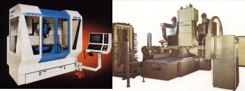
Milling machine and multi-operation machine (machining center) with numerical program management
3.3 Industrial robots
Industrial robot (IR) is a mechanical manipulator with program control.
A manipulator is a mechanical device that imitates or replaces the actions of human hands with an object of production.
Industrial robots are divided into technological (change
properties of the object) and transport.
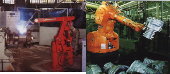
The technological robot performs welding, the transport robot moves the workpieces to the processing zone.
By carrying capacity are divided into:
 Object weight ultra-light up to 1 kg light 1-10 kg medium 10-100 kg heavy 100-1000 kg extra heavy over 1000 kg
Ultra-light robots assemble the device, a heavy robot moves large-sized workpieces.
PR are also subdivided according to the number of degrees of freedom of the working body, according to the CNC system (closed and open, contour and position, CNC, DNC, HNC).
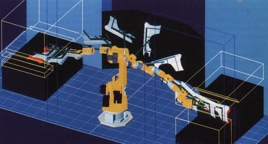
The service area of the transport robot and the trajectory of the movement of the workpiece
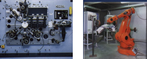
Currently wide use received transport robots that load process equipment, deliver blanks from the warehouse and transport parts to the warehouse. In the production of stamping operations, transport robots supply blanks to the stamp and remove them.
Widespread use has been made of robots that weld car bodies and paint them. Robots are used in the assembly of electronic equipment, watches and other devices.
Together with technological equipment with CNC systems, industrial robots form the basis for complex production automation.
Robots weld car bodies and install wooden panels to the processing machine (examples of robot applications)
![]()
Test questions:
1. What CNC systems allow you to process spherical surfaces on lathes?
2. What CNC systems should be used on drilling machines?
3. By how many coordinates is interpolation possible when processing workpieces on lathes? - on milling machines?
4. What is the difference between cyclic program control systems and CNC systems?
5. What functions do industrial robots perform?
Sample questions of the test control card.
In what operations is it advisable to use CNC systems with contour control?
BUT). When turning stepped rollers.
B) . When milling surfaces of double curvature.
AT). When processing holes in printed circuit boards.
What types of robots are used for painting complex-shaped parts? BUT). Technological with contour control.
B). Large-sized with position control.
AT). Transport with contour control.
In general, I believe that it is not the UE that should be evaluated in monetary terms, but the technology introduced into production. It takes a few seconds to get NC, to set processing strategies in CAM is also not long, but the lion's share of time is spent on task analysis: study of design documentation, machine park, tool base, development/manufacturing of fixtures (or USP assembly), selection of cutting modes, drafting route map(and its coordination with other production sites) or analysis of an existing route map, drawing up a setup map, coordinating the results with the customer, taking into account his wishes for machine time / tool cost / tool life / end result "from under the machine". Here, in accordance with these (and many other factors), the appropriate strategies are selected in CAM and the corresponding UE is obtained. Also, do not forget about the likelihood of changes that pop up in the production process. And, also, do not forget about the responsibility for the timing and integrity of equipment and expensive tools, workpieces, etc.The question arose: what is the adequate price for a written program for processing a specific part? I searched on the Internet - there are a lot of offers, but the prices are not announced. Could someone tell me the prices, it would be nice to have prices depending on the complexity of the part or by what criteria to evaluate your work. It is also possible that you will have to deal with the machines, and then train the operator, what price to demand for this? Tell me, I don't even know myself. =\
P.S. Correct the title of the topic, otherwise I can’t find it myself =\
Personally, I can say about myself that in the case of working remotely, I communicate with the customer approximately according to the following principle. Based on the estimated time to complete the work. I multiply it by 2 (taking into account unforeseen circumstances on the part of the customer). I multiply the received time by $100/day. I multiply by the complexity factor (I take into account the complexity of the work, the price of the workpiece, tool, etc., as well as the benefit that the customer derives from my work). I take into account the nature of the relationship with the customer (if the customer is reliable and proven, then I give a discount). I usually multiply the term for the performance of work by 2 more (this does not go into payment, because this is a term for unforeseen circumstances on my part). I announce to the customer the amount and terms, and also thoroughly explain what services are included in this amount (to avoid misunderstandings).
On the issue of tuition rates: offices providing such services, for weekly basic course take around 30k.r. from a person. From this amount and be guided.
Companies producing CNC systems adhere to the ISO standard, but often allow deviations. This is due to the "weakness" of the microcomputer in the implementation of multi-parametric technological commands (for example, changing tools). Therefore, when compiling programs for a specific CNC system, it is necessary to focus on the "User's Manual", which is included in the documentation set for the programming machine.
The ISO-7bit code defines a character as a seven-bit binary number. If the number of holes on the punched tape that define the bits of this character is odd, then the DPD (data preparation device) automatically complements the encoding of this character with a hole on the eighth track - a parity bit. For the EIA code (America, Japan), the eighth track is the control for the odd number of holes.
In the UE, the movement is programmed, defined by the coordinate axes X, Y, Z, or rotation around them, respectively, A, B, C (for example, the rotation of the machine table). Letters U, V, W define the secondary movement functions, parallel to the X, Y and Z axes respectively.
UE is a sequence of numbered sentences called frames. The frame number is a label by which you can find the required frame in order to edit it or start the NC from this frame. When constructing the UE, only the information that changes with respect to the previous part of the program is recorded in the frames.
The frame is made up of words. Each word has an address (one of the Latin letters) and a decimal number. Decimal number is written in a word according to the word format. AT modern systems numbers are usually written with a decimal point, however, it is necessary to clarify the number format according to the user's instructions for a particular machine (there are CNC systems where the word format is determined by a parameter stored in the CNC RAM).
At the end of the block, the LF character (carriage return) is written. For example: N10 G90 X10,2 Z-100 (LF) In block no. 10, a movement is defined in the absolute reference system (G90), to a point with coordinates (10.2, -100). The LF character can only be seen on punched tape, it is invisible on the display. It is also not affixed to the listing of the UE.
Words in NC blocks can be entered in any sequence, the CNC will first process the commands of the technological functions S, F, T, M and then the preparatory G, with the performance of dimensional movements.
Modulo UE control.
As noted earlier, the ISO-7bit code assumes when encoding characters, even number holes in punched tape. If we consider the character code as a binary number, then according to the ISO standard, it must contain an even number of ones. This property guarantees checking against a single error (loss of one bit or one extra bit). Therefore, some systems use more reliable appearance modulo control.
The data preparation device (PDD) when recording UE frames automatically calculates the checksums for each frame and divides them by 10, determining the remainder of the addition (mod) to a multiple of 10. This addition will be the checksum (0....9) for the frame and the UPD will be written automatically after the “end of frame” (LF) character. The CNC, when reading NC blocks, also calculates the padding for each block and compares them with the paddings on the program medium. If these values do not match, it causes an error message on the program medium. The checksum is equal to the sum of the numeric codes of all characters, including the "end of frame" (LF) character. The character code is a binary number, for example code N 1001110| 2=78| ten
Fragments of NC for a CNC machine
Preparatory Functions G
Attention: The NC command functions are not given for a specific CNC model, but are their generalized forms for developing programs in the course and graduation design. Functions with address G, called preparatory functions, determine the mode and operating conditions of the CNC machine. They are coded G00 to G99. 4
G00 Positioning. Move to the programmed point at rapid traverse.
G01 Linear interpolation. Moving in a straight line at fast feed.
G02 Clockwise circular interpolation Movement along a circular arc in a clockwise direction when viewed from the positive direction of an axis perpendicular to the plane of motion.
G03 Circular interpolation counterclockwise Movement along an arc of a circle counterclockwise when viewed from the positive direction of an axis perpendicular to the plane of motion.
G04 Pause. Initializes the delay in the execution time of the NC.
G17 G18 G19 Selection of the circular interpolation plane. Specifying the plane XY - G17, XZ - G18, YZ - G19 when programming the movement along the circular arc and compensation for the cutter diameter.
G25 Program repeat Multiple repetition of a group of NC blocks.
G41 G42 Cutter diameter compensation left and right. Used to shift the toolpath of the cutter center relative to the contour being machined.
G60 Fine positioning Move at rapid traverse, approaching a position from one direction.
G81 … G89 Canned cycles. The movements of typical surfaces of parts are programmed.
G80 Canned cycle cancel. Cancels canned cycles
G81 G89 G90 Absolute dimension. Programming of coordinates in absolute reference system.
G91 Incremental size. Programming of coordinates in relative reference system.
G92 Coordinate system setting. Determines the origin of the coordinate system relative to the specified position of the working bodies of the machine.
G94 G95 Determine the unit of feed value
G94 - mm/min
G95 - mm/rev G96 Constant cutting speed. Programming processing with a constant cutting speed.
G98 G99 Define properties in canned cycles. Set the return point after running G81 89
Auxiliary functions M
M00 Technological stop. After executing the command, the program is stopped. Continuation of work - pressing the "Start" key.
M01 Stop with confirmation. The M01 command is executed, provided that the corresponding key on the control panel is pressed.
M02 M30 Program end. End of program block. The command to complete the processing of this UE. There can be several programs on a program carrier (magnetic tape, punched tape). This command actually means "end of tape".
M03 M04 Spindle rotation. The direction of spindle rotation is clockwise. The direction of spindle rotation is counterclockwise.
M05 Spindle stop Causes spindle stop, turns off cooling. M06 Tool change. Puts in the working position the tool, the number of which is determined by the address T.
M08 M09 Coolant supply. Turns on cooling. Turns off cooling.
M19 Oriented spindle stop. Causes the spindle to stop at the specified angular position.
M17 End of subroutine. M20 Communication with an external device. It can set the transfer of control to an industrial robot, initialize the operation of a transport and storage device, etc.
M41 M42 M43 Spindle speed range. Sets the spindle speed range number.
It should be noted that a number of functions, such as "absolute reference system - G90", the dimension of the feed value (G94, G95), diameter compensation (G40) and others, are automatically set when preparing the machine for operation (turning on the power supply). They are called "default functions" and their initial state is specified in the "User's Instructions".
Under address F, the feed value is programmed, and S is the value for the spindle speed. The address letter H determines the corrector number for the length, and D for the diameter.
We also recommend
 Hero pioneers in the Great Patriotic War Heroes of the Patriotic War pioneers presentation
 Presentation "Formation of posture in preschool children Hygiene of correct posture presentation for children
 Sciences of the human body
 Presentation "history and prospects for the development of robotics"
 The value of the struggle of Russia with the Polovtsy
 Asia and Africa after World War II