Drilling machine - purpose, classification. Drilling machine
On the frame (column) 1 of the machine (Fig. 6.4), the main components are located. The frame has vertical guides along which the table 9 and the drilling head 3 move, carrying the spindle 7 and the engine 2. The gearboxes and feeds are controlled by handles 4, manual feed- with a steering wheel 5. Control of the depth of processing is carried out according to the limb 6. Electrical equipment and a counterweight are placed in a niche. In some models, a cabinet 12 is provided for electrical equipment. The base plate 11 serves as a support for the machine. In medium and heavy machines, its upper plane is used for setting workpieces. Sometimes internal cavities foundation slab are coolant reservoir. The machine table serves to fix the workpiece. It can be movable (from the handle 10 through a bevel pair of gears and a lead screw), fixed (removable) or swivel (folding). The table is mounted on the guides of the frame or made in the form of a pedestal mounted on a foundation slab.
Rice. 6.4. Vertical drilling machine model 2H125:
1 - column (frame); 2 - engine; 3 - drilling head; 4 - handles for switching gearboxes and feeds; 5 - manual feed wheel; 6 - dial for controlling the depth of processing; 7 - spindle; 8 - cooling nozzle; 9 - table; 10 - table lifting handle; 11 - foundation plate; 12 - electrical cabinet
The coolant is supplied by an electric pump through hose 8. Lubrication of the drilling head units is also carried out using a pump. The remaining nodes are lubricated manually.
The drilling head (Fig. 6.5) is a cast iron casting in which gearboxes and feeds, a spindle and other mechanisms are mounted. The gearbox includes two- and three-crown gear blocks, which are switched using the handle 15 and impart various angular speeds to the spindle. This is done by a cam-gear mechanism that transmits the movement to the rods on which the forks connected to the switch blocks are mounted. For example, the spindle of the machine tool model 2H135 has twelve speed steps (from 31.5 to 1400 min -1) provided by a gearbox and a two-speed electric motor 16. The gearbox is attached to the drilling head 4 from above.
![]()
Rice. 6.5. Drill head:
a - general form; b - kinematic diagram; 1 - gearbox; 2 - feed box; 3 - handle; 4 - head body; 5 - steering wheel; 6 - mechanism; 7 - rack and pinion; 8 - spindle for one or more tools; 9 - sleeve; 10 - control panel of an automated machine; 11 - push-button control station of the universal machine; 12 - mechanism for setting the depth of processing; 13 - mechanism for accelerated movement of the spindle; 14 - electric drive of the accelerated movement of the spindle; 15 - handle; 16 - two-speed electric motor; 17 - clip; 18 - cam; 19 - casing; MF - clutch
The spindle of the machine receives rotation from the spline gear included in the gearbox 1, which allows the spindle to simultaneously rotate and move in the axial direction together with the sleeve. Axial loads that occur during drilling are taken up by bearings mounted in the spindle sleeve.
Feed box 2 provides nine feeds in the range of 0.1...1.2 mm/rev. Feed switching is carried out by handle 3. The feed box receives rotation from the shaft VIII of the gearbox connected to the spindle with a constant gear with gears z = 34 and z’ = 60.
The transmission of motion from the steering wheel 5 of the mechanism 6 through the rack and pinion gear 7 directly to the sleeve 9 of the spindle 8 is carried out with the clutch MF engaged. The figure shows the machine spindle with a four-spindle head mounted on it.
To extract the tool from the spindle taper, a special mechanism is used, consisting of a knockout cam 18, a holder 17 and a casing 19. When the spindle is raised, the holder is held by the lower wall of the drilling head housing, and the spindle, continuing to go up, carries along the cam, which is hinged in it . The end of the cam rests against the stopped cage, the cam turns and squeezes the tool out of the spindle cone.
Machines are equipped with devices for automatic shutdown mechanical feed when the specified processing depth is reached. The depth of processing is set using the mechanism 12, mounted on the left side of the head. The mechanism is driven by a gear pair and has a disk with cams for setting the drilling depth and automatic shutdown with reverse, as well as a dial for visual reading.
The time spent on auxiliary moves is reduced due to the mechanism 13 of the accelerated movement of the spindle with an electric drive 14. The control of the universal machine is carried out using the push-button station 77, and the automated machine - panel 10.
test questions
- Tell us about the main components of a vertical drilling machine.
- Show in fig. 6.5, b kinematic chains of spindle rotation and movement of its feed.
MINISTRY OF TRANSPORT OF THE RUSSIAN FEDERATION
FEDERAL RAILWAY TRANSPORT AGENCY
FEDERAL STATE BUDGET EDUCATIONAL INSTITUTION
HIGHER PROFESSIONAL EDUCATION
OMSK STATE UNIVERSITY OF TRANSPORTATION
(OmGUPS(OmIIT))
Department of TTM and RPS
THEMATIC REPORT
ON TRAINING PRACTICE
9.1. The main parts and components of a vertical drilling machine.
9.2. Classification of metalwork hammers and their purpose, requirements for operation.
Completed by: Kuzmin Vladislav Viktorovich,
EMF student, group 42-G
Checked by: Associate Professor of the Department of TTM and RPS
Belan D.Yu.
UDC 621.94; 683.3
ESSAY
Report: 14 p., 9 fig.
countersinking
pricing
gear
the object of the study is the main parts and assemblies of a vertical drilling machine, as well as metalwork hammers, their qualification and purpose.
The purpose of the work: to study in detail the device of a vertical drilling machine, its main parts and assemblies, the procedure for use and the rule for preparing for use;
study in detail the classification of locksmith hammers and their purpose, the procedure for use and the rule of preparation for use;
understand and follow the safety rules when performing plumbing work.
The results of the work: to obtain primary skills in the use of vertical drilling machines and metalwork hammers;
to consolidate in practice the knowledge gained in theoretical classes;
Strictly follow the safety rules when working with metalwork tools and equipment.
Introduction ................................................ ................................................. .............. 4
1. The main parts and assemblies of the vertical drilling machine……………...... 5
1.1. Stationary drilling equipment………………………………… 5
1.2. drilling desktop machine…………………………………………. 6
1.3. Vertical drilling machine………………….................................................. 7
2. Classification of metalwork hammers and their purpose, requirements for operation…………………………………………...................... .................... eight
2.1. Types of hammers………………………………………………………………... 8
2.2. Separation by functional purpose………………………….. 11
Conclusion................................................. ................................................. ......... thirteen
List of references .............................................................................. ................... fourteen
INTRODUCTION
Before proceeding to the study of the issues of the topic of the essay, I suggest that you familiarize yourself with such concepts as a locksmith and his professional functions, and locksmith work, in order to understand how important this profession is, to understand its entire essence, and, of course, to answer questions about the topic of the essay .
Locksmith - a specialist in the maintenance of mechanical equipment and / or its adjustment, using locksmith tools in production or at home.
Professional functions - performs such basic types of plumbing work as: assembly, marking, replacement or restoration of mechanisms, metal cutting, metal filing, metal bending, threading with a tap or die (manually), grinding, scraping, assembly work, etc.
locksmith work - this is the processing of metals, usually supplementing machine tool machining or completing the manufacture of metal products by connecting parts, assembling machines and mechanisms, as well as their regulation. Locksmith work is performed using manual or mechanized locksmith tools or on machines. The metalwork craft received special development after the Great October Socialist Revolution. Our scientists, engineers, technicians and workers have done a lot to replace heavy, inefficient manual labor with work by machine mechanisms. With the advent of machine tools and their improvement, the role and share of manual labor, which began to be replaced by the labor of planers, turners, millers, grinders, etc. But one of the leading professions is a locksmith. The work of a master locksmith is still valued, from which the ability to perform all types of manual metal processing is required.
Thus, we see that the profession of a locksmith is very important to this day, but at the same time very dangerous, because. some types of locksmith work are performed manually, so safety regulations must be observed.
1. The main parts and components of the vertical drilling machine
1.1. Stationary drilling equipment
Stationary equipment is equipment that is located on permanent place, while the workpiece is delivered to it. Stationary equipment includes tabletop, vertical and radial machines.
The desktop drilling machine (Fig. 1) has a wide variety of designs, but the principle of their operation and scope are approximately the same.
a) general view; b) drive unit
1 - table; 2,8,10 - handles; 3 - three-jaw chuck; 4 - spindle;
5 - collar; 6 - limbus; 7 - casing; 9 - electric motor; 11 - head;
12 - column; 13,15,24 - ball bearings; 14 - glass; 16.22 - pulleys;
17 - adapter sleeve; 18 - clutch; 19 - flange; 20 - screw; 21 - thrust washer; 23 - gear; 25 - vernier
Picture 1 - Desktop drilling machine
1.2. Drilling desktop machine
As an example, consider a high-speed micrometer-feed, high-speed, high-precision tabletop drilling machine designed to drill holes with a diameter of 0.3 to 4.0 mm.
The main load-bearing units of the drilling bench are table 1 and column 12, which is bolted to the table. The head 11 moves along the column in the vertical direction. The head is moved using the screw 20, driven by the handle 8. An electric motor 9 is installed on the trunk of the head, on the shaft of which a four-stage pulley 22 is fixed. A flange 19 with a hole for screw 20. A thrust washer 21 is installed on the flange, which limits the rise and fall of the head along the column. A hole is made in the front part of the head, in which the cup 14 moves. Inside the cup, in ball bearings 13 and 24, a spindle 4 is installed, and a three-jaw drill chuck 3 is mounted on it. The spindle is connected to a slotted adapter sleeve 17, on which it is installed and fixed with screws pulley 16. The adapter sleeve rotates in bearings 15, pressed into the clutch 18, connected to the head with screws. Pulleys 16 and 22 are interconnected by V-belts. The spindle speed varies depending on the installation of the belts on the pulleys. The V-belt drive is covered with a casing 7. A three-jaw chuck 3 is installed on the tapered shank of the spindle. The cup 14 with the spindle, chuck and drill is fed by turning the handle 2 connected to the gear shaft 23. When the handle is turned, the gear engaged with the gear rack of the cup lowers it with spindle and drill to a given depth. Clamp 5 on the shaft of the handle 2 limits the depth of drilling. A more accurate feed of the drill when drilling holes in parts is carried out according to the limb scale 6 and the vernier 25. The machine head is fixed when it is raised and lowered using the handle 10.
Vertical drilling machines are the main and most common type of drilling machine used for making holes in relatively small parts. These machines allow you to perform the following types of work: drilling, reaming, countersinking, countersinking, spotting and reaming. The range of these operations can be significantly expanded by using a special tool.
Machine mod. SB 501/1 (Fig. 7.1) is designed for drilling, reaming, countersinking and reaming holes in various parts, as well as for facing and threading with machine taps.
Rice. 7.1. Desktop vertical drilling machine mod. SB 501/1:
1 - base plate, 2 - drilling table, 3 - protective cover, 4 - drill chuck, 5 - spindle, 6 - housing, 7 - cover, 8 - gearbox, 9 - engine, 10 - handle, 11 - rack, 12 - table clamp screw.
On the machine mod. SB 501/1 workpieces of relatively small dimensions and weight. The machine is a base plate 1 with stand 11 along which the rotary drilling table moves and is set at the desired height 2 . The machine has a belt gearbox 8 , which is located in the upper part of the case and is closed with a lid 7 . An engine is attached to the body of the headstock 9 . The cutting tool is fixed in the chuck 4 which is attached to the spindle 5 . With handle 10 the vertical movement of the spindle. A switch is used to turn on the machine. Green colour, to turn off - red. The rotational moment from the motor shaft is transmitted through the gearbox to the spindle.
Spindle 5 rotates (the main movement AT 1 ) with a frequency of 277-2440 rpm idling. The workpiece to be processed is placed on the drilling table. 2, having installation vertical P 1 and rotational B 2 movement around the machine stand and B 3 around the axis perpendicular to the axis of the stand 11 . The table is fixed with a clamp screw 12 . Feed movement P 2 carried out by a lever device when a finger is pressed on the handle 10.
The technical characteristics of the machine are presented in Table 7.1.
Table 7.1 - Technical characteristics of the machine:
Purpose, device and principle of operation of the drilling device
The device drilling with the drive is intended for drilling of openings in preparations from wood and other materials in living conditions. According to its characteristics, the electric drive belongs to household electrical appliances with protection class II according to GOST 27570.0.-87.
The main technical characteristics of the device are given in Table 7.2
Table 7.2 - Technical characteristics of the drilling device
|
Drill diameter, mm | |
|
Range of nominal spindle speeds, min -1 | |
|
Voltage of alternating single-phase current with a frequency of 50 Hz rated, V | |
|
Useful power, W | |
|
Power consumed rated, W | |
|
Operating mode intermittent work, min pause, min | |
|
Threaded spindle | |
|
Axis distance range seat kind of electric drive to the rack axis, mm Without reinstallation With reinstallation | |
|
Range of distances from the upper plane of the seat of the electric drive to the base, mm Without rod With a barbell | |
|
Working drilling depth, mm, no more | |
|
Overall dimensions, mm, no more | |
|
Weight, kg, no more |
The drilling device (Fig. 7.2) consists of a base, an electric drive and mechanisms for vertical and horizontal movements. To the base 1, on which a vice can be installed or a workpiece can be fixed, a vertical rail 2 is attached with screws, which carries a bracket 9 with a traverse 3. An electric drive 4 with a gearbox is installed on the traverse, which ends with a spindle 5. A drilling machine is screwed onto the spindle. cartridge 6.
The electric drive has the ability to move along the traverse in the horizontal direction due to the rack and pinion with the help of the handle 7, the amount of movement is counted on the dial of the readout device 8. After positioning the spindle axis in desired position, it must be fixed on the traverse by turning the knob 9.
The vertical movement mechanism is a spur gear, the gear wheel of which, together with the bracket 9, moves along the rail 2 when the handle 10 is turned.
In the hole of the bracket 9 passes the adjusting rod assembly 12, connected with the collar 13, which serves to fix the drilling depth and together with the spring 14 to return the traverse to the upper position. The bracket 9 and clamp 13 are fixed on the rail 2 by the handle 15 and the nut 16. The dowels prevent the bracket 9 from turning around the rail 2.
Installations for automatic welding of longitudinal seams of shells - in stock!
High performance, convenience, easy operation and reliable operation.
Welding screens and protective curtains - in stock!
Protection against radiation during welding and cutting. Big choice.
Delivery throughout Russia!
In vertical drilling machines, the main movement is the rotation of the spindle with the tool fixed in it, and the feed movement is the vertical movement of the spindle. The workpiece is usually installed on the machine table or on the foundation plate if it has large overall dimensions. The alignment of the workpiece holes and the spindle is achieved by moving the workpiece.
On the frame (column) 1 of the machine (Fig. 6.4), the main components are located. The bed has vertical guides along which the table 9 and the drilling head 3 move, carrying the spindle 7 and the engine 2. The gearboxes and feeds are controlled by the handles 4, manual feed - by the steering wheel 5. The processing depth is controlled by the limb 6. Electrical equipment and counterweight. In some models, a cabinet 12 is provided for electrical equipment. The base plate 11 serves as a support for the machine. In medium and heavy machines, its upper plane is used for setting workpieces. Sometimes the internal cavities of the foundation plate are a coolant reservoir. The machine table serves to fix the workpiece. It can be movable (from the handle 10 through a bevel pair of gears and a lead screw), fixed (removable) or swivel (folding). The table is mounted on the guides of the frame or made in the form of a pedestal mounted on a foundation slab.
The coolant is supplied by an electric pump through hose 8. Lubrication of the drilling head units is also carried out using a pump. The remaining nodes are lubricated manually.

The drilling head (Fig. 6.5) is a cast iron casting in which gearboxes and feeds, a spindle and other mechanisms are mounted. The gearbox includes two- and three-crown gear blocks, which are switched using the handle 15 and impart various angular speeds to the spindle. This is done by a cam-gear mechanism that transmits the movement to the rods on which the forks connected to the switch blocks are mounted. For example, the spindle of the machine tool model 2H135 has twelve speed steps (from 31.5 to 1400 min -1) provided by a gearbox and a two-speed electric motor 16. The gearbox is attached to the drilling head 4 from above.
The spindle of the machine receives rotation from the spline gear included in the gearbox 1, which allows the spindle to simultaneously rotate and move in the axial direction together with the sleeve. Axial loads that occur during drilling are taken up by bearings mounted in the spindle sleeve.
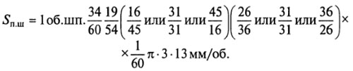
The equation of the kinematic chain of spindle rotation
Feed box 2 provides nine feeds in the range 0.1... ... 1.2 mm/rev. Switching feeds is carried out by handle 3. The feed box receives rotation from the shaft VIII of the gearbox connected to the spindle with a constant gear with gears z = 34 and z = 60.
The equation of the kinematic chain of the movement of the spindle feed
The transmission of motion from the steering wheel 5 of the mechanism 6 through the rack and pinion gear 7 directly to the sleeve 9 of the spindle 8 is carried out with the clutch MF engaged. The figure shows the machine spindle with a four-spindle head mounted on it.
To extract the tool from the spindle taper, a special mechanism is used, consisting of a knockout cam 18, a holder 17 and a casing 19. When the spindle is raised, the holder is held by the lower wall of the drilling head housing, and the spindle, continuing to go up, carries along the cam, which is hinged in it . The end of the cam rests against the stopped cage, the cam turns and squeezes the tool out of the spindle cone.
The machines are equipped with devices for automatically switching off the mechanical feed when a predetermined processing depth is reached. The depth of processing is set using the mechanism 12, mounted on the left side of the head. The mechanism is driven by a gear pair and has a disk with cams for setting the drilling depth and automatic shutdown with reverse, as well as a dial for visual reading.
The time spent on auxiliary moves is reduced due to the mechanism 13 of the accelerated movement of the spindle with an electric drive 14. The control of the universal machine is carried out using the push-button station 11, and the automated machine - panel 10.
It is convenient and fast to drill holes on a drilling machine. Drilling machine refers to technological machines. Technological machines are designed for processing various materials. Like any technological machine, a drilling machine consists of three main parts: an engine, a transmission mechanism and an actuator (Fig. 139).
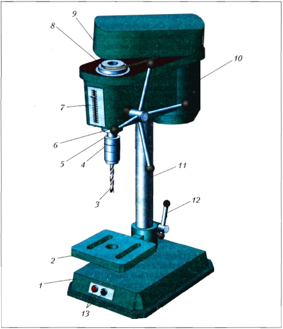
Rice. 139. Drilling machine: 1 - base (bed); 2 - desktop; 3 - drill; 4 - cartridge; 5 - working shaft; 6 - drill feed handle; 7 - drilling depth scale; 8 - pulley with a belt; 9 - protective cover; 10 - electric motor; 11 - column; 12 - stopper; 13 - start buttons
Before starting work on the machine, it is inspected and checked for serviceability. A drill of the required diameter is inserted into the cartridge and a drill of the desired diameter is attached with a special key. The drill must be clamped in the chuck straight, without distortion. A workpiece is fixed on the desktop, on which the center of the future hole is marked. The “Start” button turns on the electric motor, which, by means of a belt drive, rotates the working body (spindle with a chuck and a drill). By turning the handle, the spindle (working shaft) with the drill is fed onto the workpiece. The drilling depth is measured on a scale from the moment the drilling starts. After drilling the hole, the drill is raised. The machine is turned off.
When drilling, large workpieces are held with the left hand, and small ones - in pliers or a vice.
At enterprises, drillers, or CNC machine operators (computer numerical control), work on drilling machines.
Practical work No. 42
Studying the device of a drilling machine and working on it
Rules for safe work
- Work on the machine only in special clothes: overalls or a dressing gown, as well as a headdress.
- Drill only with protective goggles.
- Clamp the workpiece securely.
- Stay away from a running machine.
- Remove chips with a brush when the machine is stopped.
Work order
- Study the design of the drilling machine.
- Explain the principle of its work.
- Fix the drill in the chuck.
- Mark, punch and secure the workpiece in a vise.
- Turn on the machine and drill a hole.
- Turn off the machine and use a brush to collect the chips in a scoop.
New concepts
A drilling machine is a technological machine, construction, machine parts (engine, transmission mechanism, actuator), driller, CNC machine operator.
test questions
- Show the engine, transmission mechanism and working body of the drilling machine.
- What is the transmission mechanism made of and what is it used for?
- What is the actuator of a drilling machine?
- How to fix workpieces when drilling: small, large, short, long?
- Why does a drill press have multiple drill feed handles?
- List the rules for safe operation of a drilling machine.
We also recommend
 Switching power supply: repair and refinement
 Remote control of light
 Swimming lessons for preschool children
 Notes for the master - home household alarms
 Clock propeller on Atmega8
 Device and relay application examples, how to choose and connect a relay correctly Microcontroller and relay simple switching circuits