Repair of lathe guides with composite materials. Repair of guide beds of lathes
Scraping machine guides is one of the most effective ways restoration of geometric and technical parameters this unit of turning and other units. It is used very often and shows excellent results of repair work.
1 Scraping guide beds - when is it done?
Any specialist knows that the repair of machines used on various enterprises, according to a predetermined calendar plan considered a very important procedure. During scheduled repairs, various mechanisms of processing units are restored, including guide beds.
Also, rails may need to be restored outside of the schedule if they require immediate repair. The value of their wear is determined by a special method, which we will describe. Inspection of the state of the guides is carried out using probes and a control ruler. The length of the latter is always chosen so that it is at least 2/3 of the length of the surface to be checked.
The scheme for determining the amount of wear is as follows:
- the surface of the node of interest to us is cleaned in order to remove serious scratches and nicks from it;
- the ruler is placed on the guide and the gap between them is measured using probes (measurements are made every 30–50 centimeters along the entire length of the machine element).
The place where the gap is maximum is determined as the area in which there is a maximum change in the straightness of the guide (that is, there is obvious wear on it). Next, the next step of the test is performed, which makes it possible to establish the flatness of the guide. It is done like this:
- a ruler is placed on tiles of the same geometrical parameters;
- using probes to determine the distance between measuring tool and the surface under study.
A similar operation is performed at 2-3 points along the length, and in different directions. Experienced professionals make checking even easier. They take small sheets of very thin paper (for example, cigarette paper, whose thickness does not exceed 0.02 millimeters), lay them out on guides in several areas, and then press them down with a ruler.
Further, from under the measuring device, these leaves are pulled out one by one. When the straightness of the part is not broken, you can only cut off the ends of the pieces of paper, but do not pull them out. The condition of the horizontal guides is verified using a level and a bridge:
- they are placed on that part of the frame that visually seems to be as worn out as possible (in such a section, the bubble in the level will deviate in different directions at approximately the same distances);
- move the measuring instruments to the adjacent zone, where the deviation of the bubble is noted, entering the reading into the graph-table;
- then move the bridge further and record the result again.
Based on the table, it is subsequently easy to determine exactly where the wear has occurred.
2 How the machine guides are scraped - general provisions
The bed is placed on a rigid flooring or on a special stand, after which it is examined by level in the longitudinal direction (the check described above is carried out), and then in the transverse direction. Using wedges or shoes, adjust the location of the bed as accurately as possible.
It can also be placed on the jack bolts. In this case, the adjustment of the position of the bed will be very simple, you just need to lower or raise it by screwing or unscrewing the bolts. The operation of giving the frame the correct position is continued until the bubble in the level is fixed at the zero mark.
After completing the alignment, they are determined with the base surface. It will serve as a guideline for tracking the parallelism of the restored guides. If we are talking o, the base ones are most often chosen by those guides that go under the headstock (rear). Practice shows that it is they who wear out the least during the operation of the equipment. It is advisable to pre-scrub the guides selected as the main ones. This will remove minor wear and tear.
After that, you can start scraping the bed, constantly checking the parallelism of the surfaces to be machined. To check the curvature (spiral) of the restored element, in some cases, an indicator is used. But its use is currently recognized as unreliable, due to the deviation (up to 0.01 mm) of the base guides from the horizontal. Such a deviation will give a considerable calculation error, which will be the higher, the greater the extension of the test indicator holder.
We note the fact that the parallelism of the guides under the headstock in relation to the planes of fastening of the running roller and screw, as well as the feed box, is often violated. Deviations from parallelism become greater as large quantity unit has undergone scheduled repairs. Each time, repairmen have to spend considerable time when assembling equipment, since the process of fitting the indicated roller, screw and feed box to the place is really time-consuming and complicated.
After completing the preparation of all surfaces, they begin to scrape the guides. During the procedure, their spiral twisting and parallelism are constantly monitored.
- Under clamping bars and directly under the carriage. A deviation from parallelism along the length of more than 15 microns is not allowed.
- Support (transverse). For straightness, the error is possible up to 10 microns, for parallelism - up to 15 microns (indicators are controlled by a calibration bridge and a calibration plate).
- Carriages (reciprocal guides). During work, make sure that the difference in parallelism between the screw axis and the guides does not exceed 35 microns, using a trihedral ruler.
- Carriages (longitudinal guides). If these elements of the unit are worn out badly enough, it is imperative to use anti-friction compounds to restore them. At the described stage of the work, it is important to achieve adequate coaxiality of the shaft (running) and its seating area, the reliability of the engagement of the travel rail in the longitudinal direction with the rack and pinion, the perpendicularity of the spindle axis and the movement of the caliper in the transverse direction.
In the future, restoration is carried out using the anti-friction composition of the tailstock guides. The purpose of these procedures is to achieve:
- parallelism of the guides of the frame and the axis of the quill (on a length of 20 cm, an error of up to 30 microns is possible);
- coaxiality of the hole of the quill and spindle (in the horizontal plane, the permissible deviations at a length of 30 cm are 10 microns, in the vertical plane - 30 microns).
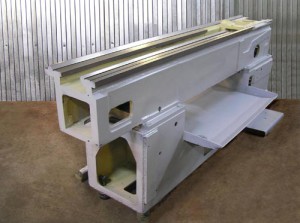
The bed of a machine tool, lathe or other, is the main base part on which almost all components and parts are located and fixed, and all moving mechanisms and parts move relative to the bed. This article will detail all important points related to accuracy, verification and restoration of the bed lathe with the help of scraping, as well as devices for this and other nuances will be considered.
The bed of any machine tool must have a sufficiently high rigidity, ensure that the machine maintains the required accuracy for a long time, and at the same time allow chips to be easily removed from the cutting zone. Moreover, with sufficient rigidity and accuracy, the dimensions and weight of the frame should be minimal. Of course, the designs and shapes of the beds are different and they are determined by the purpose and dimensions of the machine.
The bed of a medium-sized lathe is cast in the form of a hollow body part (see Figure 1), and to make the machine bed more rigid, with a small weight (and with the possibility of chip removal), the longitudinal ribs of the bed are connected diagonally (Fig. 1b) or parallel ( Fig. 1 a) partitions, which are cast as one piece with the frame.
Well, on the longitudinal ribs of the frame there are guides that are designed for the longitudinal movement of the machine support and the tailstock. The dimensions and shape of the bed guides vary, for example, on most medium-sized machines, they usually make a combination of flat and triangular guides, with the outer guides used to install and move the caliper, and the inner guides serve to install, move and secure the tailstock.
As I said, the beds of metal-cutting machines (as well as the beds of hammers and steam engines) usually have flat, triangular (V-shaped) guides, as well as prismatic ones. And guides in the form of a dovetail are made on calipers and tables of metal-cutting machines, various sliders, etc.
The accuracy of any machine, of course, depends on the accuracy of manufacturing and the condition of the bed guides and other mating parts, so the machine guides are carefully processed (well, or restored if the machine is worn out, and how and with what help this is done, I will write in detail below).
As a rule, machine beds are cast from gray cast iron (its number is according to GOST 1412-70). Most often, the beds of small and medium-sized Soviet machine tools were cast from SCH21-41 gray cast iron, while the beds of heavier machines were cast from SCh32-52 gray cast iron.
It should be mentioned that cast iron beds have a low cost of the machine, have greater vibration resistance, and besides, they are easier to process and restore). But the main disadvantage of cast iron beds is that their guides are short-lived, as they wear out quickly, and the weight of a cast iron bed is quite large (although for many machines, a lot of weight is more of a plus than a minus).
And therefore, in order to avoid the shortcomings described above, more and more often they begin to manufacture welded beds from steel, which is naturally more wear-resistant than cast iron. And for some rare heavy and dimensional machines, beds are made of reinforced concrete.
But still, cast iron beds are the most common and have their advantages. In addition, with careful care (timely lubrication and removal of chips), cast-iron beds are quite durable, besides, it is almost always possible to restore a worn-out bed, moreover, with your own hands, without having expensive longitudinal planers or grinders, but how to do this with the help of what, I will describe in detail below.
The assembly of the frame (and other components) with the parts moving along it progressively comes down to finishing the guides and fitting the interface of these parts. In mechanical engineering, the surfaces of progressively moving mating parts are finished using scraping, fine planing with wide cutters, as well as grinding and lapping.
But despite the fact that scraping is a rather time-consuming operation (and where possible it is replaced by grinding), but it is used to restore the bed guides (and not only). After all, not everyone has a grinding machine. And to restore the machine bed with the help of scraping, you just need to buy a scraper and some other tool and fixtures (which, by the way, you can make yourself, but this will be written below), and be patient.
I already wrote in detail about scrapers (what they are) and scraping, and the basics of the scraping process itself, quality control and others are also described there. important nuances. Therefore, whoever decided to competently restore the bed of his machine on his own, it is advisable to first read the first article about the scraping process by clicking on the link above, and then read what will be described by me below.
Scraping of the lathe bed, as well as translationally moving parts mating with it.
Below I will describe the scraping of the bed and the progressively moving parts of the lathe, which has a bed guide length of more than 3 m. For those who have a machine with smaller parts, it will become even easier to work.
And so, before starting work, for starters, you should remember that the planes shown in Figure 2 must meet certain requirements, which I will list below:
- guide beds must be straight in the longitudinal direction within 0.02 mm over a length of 1 meter (1000 mm);
- and the non-parallelism of the guides along their entire length should not exceed the same 0.02 mm;
- in addition, the machine bed should not be helically curved throughout its entire length, only a deviation of 0.03 mm (the smaller the better) is allowed over a length of 1 meter (1000 mm);
- the (lower) parts of the caliper mating with the frame must fit snugly against the guides of the frame, or it is allowed to insert a probe with a thickness of not more than 0.04 mm butt between it and the guide, for a length of not more than 25 mm;
- the transverse guides of the lower part of the caliper must be parallel to each other and exactly perpendicular to the guides of the bed, while the tolerance for deviations from parallelism and perpendicularity is not more than 0.02 mm, again over a length of 1000 mm;
- and the accuracy of scraping the guides should turn out to be such that when checking for paint, you get 12-15 spots in a square from a frame measuring 25x25 mm (I already wrote about quality control in detail in the article about scrapers and scraping - link to the article above);
The process of scraping the machine bed.
Before scraping, the frame must be installed on a massive base and then, using a bar (or frame) level, align the frame in the longitudinal and transverse directions. We start scraping with base surfaces.
Machine bed with caliper: 1 - plane for the tool holder, 2 - cross slide, 3 - cross slide guides, 4 and 13 - support surfaces mating with the bed, 7,8,9 - guides for the sole of the tailstock, 5,10 and 12 - upper guides for the caliper, 6 and 11 - lower guides for the clamping bars of the caliper, 14 - wedge of the cross slide, 15 - 18 - transverse guides of the caliper.
And the base surfaces on the frame are chosen so that all other guides can be scraped relative to them, and the machine support can also be installed and adjusted, planes 6, 8, 12 - see Figure 2.
The planes intended for scraping (that is, the guides of the machine bed) are checked for paint with a special ruler (for example, ShD-630 - GOST 8026) or a special plate 3 (see Figure 3 below), in which the profile of the working surface applied to the guides corresponds to the profile of the guides of the bed that need to be restored with scraping (who does not have a plate, you can also use the machine support, but of course it can be worn out and therefore it is preferable to use the plate).
On top of the plate 3 there is a special flat control platform, which is parallel to the lower surfaces and on which a bar or frame level is installed.
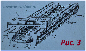
Punching beacons on the guides of the machine bed:
1 and 2 - guide carriages, 3 - scraping plate, 4 - level.
Triangular (prismatic) and flat guides are first roughly scraped along the ruler and then so-called beacons are applied to the roughly cleaned planes.
The essence of applying beacons is that on the surface of the guide, only small plot, which is slightly longer than the length of the plate itself. And you should scrape until the planes of the guides begin to be evenly painted over when checking with a plate for paint (I wrote in detail about checking for paint in an article about scrapers and scraping - link above).
Well, installed on top platform slab level should not indicate deviations from the horizontal plane, either in the transverse or longitudinal directions. Beacons are applied at both ends of the guides, but if scraping is carried out along the ruler and level, then on the rest of the machine bed, beacons must be applied at such a distance from each other that the control ruler overlaps them in length. And the closer the beacons are applied to each other, the more accurate the scraping of the guides will be.
The middle beacons are applied in the same way as the extreme ones, but as they deepen, the scraping of the beacons themselves is constantly controlled by a ruler, a plate or an “airplane” (bridge - more about it below) with a level set on them.
By executing each of the beacons (with its control on the next one), we gradually bring all the beacons to the same level and in the end they will all be located on the same straight line. It should be noted that all beacons should be placed and carried out very carefully, because later they will be the base for trimming the areas between them (beacons).
We scrape the areas between the lighthouses along the ruler in the usual way, but the painted areas (spots) on the lighthouses themselves do not scrape. Well, we scrape the areas between the beacons until the surface between the beacons and on the beacons is covered with evenly spaced spots, but in a smaller number than is necessary for the finally scraped surface of the guides.
After scraping the sections between the beacons, you should check the entire surface of the guide for straightness, if necessary, correct inaccuracies and then you can proceed to the final finishing scraping. We perform the final scraping by gloss on the plate (I wrote about checking by gloss in the first article on scraping - link above) or by gloss on the caliper, and they control the entire surface of the guides by ruler and level.
After scraping the main base (guides for the caliper), they scrape further the planes of the tailstock guides - these planes 5.7 and 10 are shown in Figure 2.
The planes of the guides of the machine bed, shown in the figure at numbers 5 and 10, are scraped along the beacons and checked using a plate, as described above. Well, we check the parallelism of the plane 10 and the prismatic guide 7 of the tailstock with the help of an indicator that is installed on the plate (I will talk about the special bridge device, or as it is also called the “airplane”, in more detail a little later).
Caliper scraping.
In general, this article is about the machine bed and its restoration, but other parts of the machine are also associated with the bed, which also wear out and should be restored, and of course it makes no sense to restore only the bed. Therefore, the scraping of the caliper will be described below.
Scraping the lower part of the lathe caliper should begin with fitting the lower sliding guide surfaces that mate (rub) with the bed guides. These planes are shown in Figure 2 at numbers 4 and 13. And since the length of these planes is very small, they are scraped and checked against the ruler and the machine bed (or on a special plate that has a profile of the working surface of the bed guides - that is, the model of the bed ). The lower sliding surfaces of the lower part of the caliper are finally scraped along the bed guides.
And when the scraping of the lower guides and the lower part of the caliper is completed, then you can start scraping the transverse guides of the caliper, the profile of which is made in the form of a dovetail - these are the surfaces numbered 16,17,18 shown in Figure 2. These surfaces (planes) are used to move caliper cross slide.
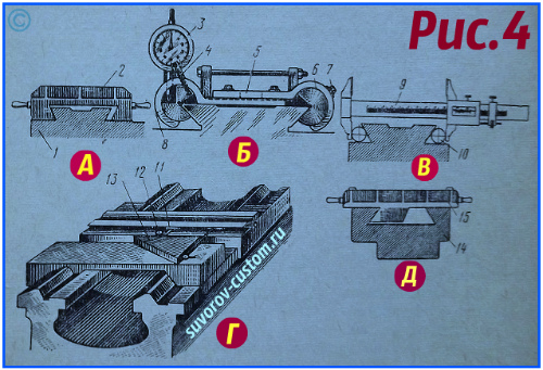
Scraping the caliper and checking the straightness of the lower caliper guides: A - scraping with a scraping plate, B - checking the caliper guides with a slider with an indicator, C - checking the caliper guides with rollers, D - checking the guides with a slider with an indicator and a control square, D - scraping an inclined surface of the guides with a scraper plate.
To begin with, we roughly scrape all the mating surfaces along the angular ruler, and then lay the lower part of the caliper 1 on the frame (see Figure 4a) and with the help of a special scraping plate 2 we scrape the transverse guides that mate with the cross feed slide of the machine caliper (if there is no special plate , then we scrape it with a scraper manually with a constant check with an angular ruler for paint).
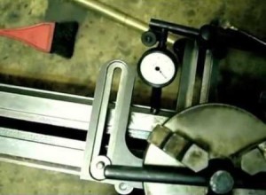
When we achieve a uniform arrangement of spots, then we can scrape the second angular (inclined) plane of the dovetail. In the process of work, it is necessary to periodically check the planes using a special device (creeper), shown in Figure 4b, on which a 3-hour indicator is fixed. Cylinders 6 are installed in this device, which are tightened with screws 7 and pin 8. Cylinders 6 of the device have an exact profile dihedral angle dovetail should be pressed tightly against the planes to be checked, then the nose of the indicator fixed on top rests against the shelf of the control square 13 (see Figure 4d).
The square 13 should be installed on a special stand (it is possible on the bottom plate of the tailstock) and then we place one of the sides of the square exactly parallel to the guides of the machine bed. And now, when moving the fixture (slider 11) along the entire length of the inclined dovetail guide, the indicator nose 12 will slide along the side of the triangle and show the deviation of this surface from perpendicularity. If, during the check, satisfactory results are visible within the tolerances (I wrote the tolerances above), then the final (finishing) scraping can be performed.
Who does not have such a device, then to check the parallelism of the planes, you can use two identical rollers shown in Figure 4c (for example, rollers from a bearing of a suitable diameter) and a caliper 9 (preferably a micrometer).
Final scraping.
We do the final scraping along the guide planes cross caliper. And when the adjustment of the three planes of the transverse guides of the caliper (one inclined and two flat) is completed, then the wedge 14 should be scraped off (Fig. 2).
At the same time, we apply paint (for example, Prussian blue) on those surfaces of the sled that mate (contact) with the wedge, then put it on the guides of the cross sled and with a small hammer, apply light blows to the wedge and insert it between the planes of the guides of the caliper and sled.
Now you need to move the cross slide several times back and forth (together with the wedge) and then carefully remove the wedge. It remains, following the traces of paint (meaning bulges), to remove them with a scraper from the surface of the wedge, that is, to scrape it.
If a new wedge is being made, then after the final scraping, we cut off the excess from the wedge (along the length) and mill the cutout for the wedge adjusting screw.
Checking the parallelism, straightness and helicity of the machine bed.
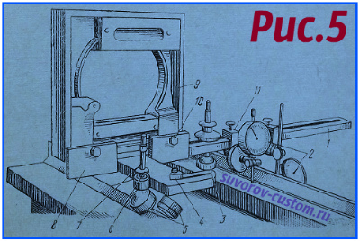
For verification, various devices are used. The most common device, called a bridge (popularly "airplane") is shown in Figure 5. It has a base 1 made of sheet metal, at least 10 mm thick, which has a T-shape (sometimes an H-shape) and four supports 5, and an additional support 3.
The supports at number 5 in the figure have the ability to move in a vertical plane along the pins 7 and clamp them with nuts 6. The other two supports can move in the horizontal plane (along the longitudinal grooves), well, they are fixed in desired position using nuts 4. Well, supports 5 can move apart and move, depending on the width of the frame guides and the difference in the distance between them. And support 3 is able to move in horizontal and vertical planes.
There is also a block 8, which is rigidly fixed to the base 1 with screws (they are not shown in the figure), and a frame level 9 is attached to the block 8 using screws 10. The level to be fixed should be with the division value of the main ampoule 0.02 ( well, or 0.05) per 1000 mm. The device also has special clamping units 11, into which two 2 are attached. The position of indicators 2 can always be adjusted, and the clamping units that fasten them can be fixed in different places on the base (depending on the size of the machine bed).
Figure 6 shows examples of checking guides using a special device - a bridge (in the people of an airplane). Figure 6a shows the verification of guides having a triangular (trapezoidal, prismatic) profile. Guides with such a profile are usually made at the beds of turret lathes.
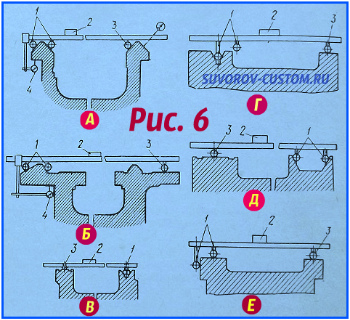 As can be seen in Figure 6a, four supports 1 of the fixture (only 2 supports are visible in the figure) are placed on the left prismatic guide of the frame, and one support 3 rests on one of the sides of the right guide of the frame. Supports are made in the form of rollers - often in homemade devices of this type, bearings of suitable size are used, but it should still be taken into account that the bearings have gaps between the races. Therefore, it will be much more accurate to install rigid supports (sliders) instead of rollers (bearings).
When moving the bridge (aircraft) along the guides of the frame, the 4-hour indicator determines the parallelism of the left guide frame relative to the base surface (the base surface in Figure 6a is where the indicator nose 4 rests).
And according to level 2 (you can use not a frame, but a bar level), which is installed across the frame guides, determine the spiral curvature of the guides (that is, the deviation of the guide surfaces in the horizontal plane). I published tolerances for deviations above in the article, I hope this is clear, let's move on.
Checking the second side of the right guide frame is carried out according to the level, you just need to move it to this (second) side of the support 3 (the second support 3 is not visible in the figure), or simply rearrange the indicator, resting its nose against the second plane of the right guide frame (with such a check in figure 6a, the indicator spout is shown by a dotted line).
Well, to check the straightness of the surfaces of the machine bed, the level must be placed on the bridge (airplane) not across, but along the guides, and then the bridge should be moved along the guides, periodically stopping it in different parts of the bed and recording (removing) level readings.
Figure 6b shows a bridge (popularly an airplane) mounted on a lathe bed to control and check the parallelism of the middle guides relative to the base surface. And the base surface is the plane for the gear rack (in Figure 6b, this plane is shown in thick short line and indicator 4 rests against it).
Figure 6b also shows a method for checking the bed for helical curvature. Only the parallelism of the guides is checked using the indicator 4, and the spiral curvature is controlled using the bar level 2.
The external guides are also checked using a dial indicator and a bar level, only after the bridge has been readjusted and installed on these external guides, or only with the help of a dial indicator, and as a base, using the verified middle guides of the bed.
Well, Figure 6c shows the verification of the guides of the bed of the grinding machine. For such machines (and some others), as a rule, guides are made that have planes of a different shape (a combination of V-shaped and W-shaped profiles) - they are visible in Figure 6c.
To check such beds for straightness and helical curvature of the guides, four supports 1 (between the V-shaped planes) and one support on the opposite plane of the other guide are installed on them. Control (check) is carried out using the bar level 2.
Figure 6 d shows a verification option if the dimensions of the guides do not allow placing all the supports of the bridge (aircraft) between their generatrix planes. In this case, we install only two supports 1 and one support 3 on the second guide. We do not use other supports 1.
And Figure 6d shows such an installation of the bridge, in which the supports 1 are separated at a decent distance between the prismatic surfaces of the guide frame.
Well, the last figure 6e shows how flat bed guides are checked. With such a check, the main feature is that the two supports 1 rest against side surface(only one support 1 is visible in the figure), and the remaining two supports and support 3 rest against the horizontal planes of the guides. This setting provides an accurate reading of the level 2 setting on the bridge.
As soon as the preparation (checking) of the base surfaces has been made, the scraping of the bed guides can begin.
Other ways of processing (restoring) the bed of machine tools.
In well-equipped factories, scraping is replaced by grinding, since grinding is more productive and more accurate than scraping (of course, with high-quality equipment). In addition, with the help of grinding, hardened parts with high hardness can also be processed.
For grinding the guide beds of various machines, special grinding machines(universal or surface grinders) and special fixtures that only large enterprises. In the absence of grinding machines suitable sizes, processing of parts can be performed on milling, planing and carousel machines using special grinding heads.
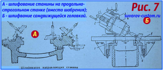 Figure 7 A shows a diagram of grinding the lathe bed on a planer using a universal grinding head. The use of such heads makes it possible to replace manual scraping in mechanical repair shops.
And figure 7B shows the processing of the bed using a self-propelled grinding head. Its advantage is that it does not require large planers. And thanks to a special device, such a head makes reciprocating working movements along the workpiece being ground.
On the plate 5 there are replaceable guides 1 and 6 (see Figure 7B), and the grinding head 4 is an electric motor with an elongated shaft, at the end of which a cup abrasive wheel is attached. There are also two swivel supports 2 and 3, which allow you to set the head at the desired angle, and a worm gear with a separate motor moves such a grinding device.
Well, the change in the rotation of the electric motor of the gearbox (to ensure reciprocating motion) is carried out automatically (along the stops), well, or manually.
But still, for small garage workshops and just amateur craftsmen who have a lathe or milling machine in their workshop that need to be restored, scraping is the most affordable and inexpensive way repair, and it will be used for the restoration of machine tools for a long time to come.
And I hope that this article will be useful to many novice craftsmen who decide to put the machine in order in their workshop, turning or milling, it doesn’t matter, because the principle of repairing and checking the guides of the machine bed is almost the same, success to everyone.
Lathes are used to process cylindrical workpieces. They include many varieties that differ in size and availability of additional functions. Such industrial models as are very common and widely used in modern industry. In order for the device to function normally, you need to know all the features of its parts.
The lathe bed serves to fix almost all mechanisms and assemblies that are used on this equipment. Often it is cast from cast iron to get a massive and solid construction which could last for a long time. This is due to the fact that it will be subjected to heavy loads. You should also not forget about stability, since massive large models use tremendous energy during operation and the base must resist loads well.
The bed and guides of the machine are fastened with bolts to cabinets or paired legs. If the device is short, then two racks are used. The longer it is, the more racks may be required. Most of the cabinets have doors, which allows them to be used as drawers. The guides must be handled with great care and protected from damage. It is not advisable to leave tools, blanks and other products on them. if you still have to place metal objects on them, then before that you should put a wooden lining. For better care, before each use of the machine, the frame must be wiped and lubricated. When the work is completed, chips, dirt and other excess objects should be removed from it.
The design features of the frame of metal-cutting machines may differ depending on the specific model, as they are designed for convenient and safe placement of all equipment components. But the basic provisions in many cases remain the same, so the basics can be considered using the example of popular models.
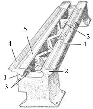
photo: cast iron bed device
- Longitudinal rib;
- Longitudinal rib;
- A transverse rib that serves to connect the longitudinal ribs;
- Prismatic guides of longitudinal ribs;
- Flat guides that serve to install the tailstock and headstock, as well as to move the caliper along them;
It should be noted that the bed guides transverse section may have various forms. A mandatory rule is to observe a parallel arrangement, so that everything should be equidistant from the axis of centers. This requires precise milling or planing. After that, the operation of grinding and scraping is carried out. All this ensures accurate processing of products, as well as the elimination of problems with the movement of the caliper and the occurrence of shocks.
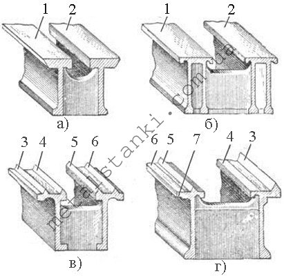
- The frame of the lathe for metal, which is shown in figure "a" under numbers 1 and 2, has a trapezoidal section of the guides. In this case, the main emphasis is on a large supporting surface. They have great wear resistance, which allows you to keep their accuracy for a long time. At the same time, it takes a lot of effort to move the caliper along them, especially if it is warped.
- Figure "b" shows a bed with a flat rectangular section guides. Unlike the previous one, they already have two stiffeners, and not one, which makes them stronger.
- Figure "c" shows a frame with triangular guides. Given the fact that a fairly small supporting surface is used here, it is difficult to work with a large weight, so this type is used mainly for small machines.
- Figure "d" shows a frame with a triangular section and a reference plane. In this case, it is also used for machines of small sizes.
If the bed is intended for a heavy machine, then it has not only a large cross section, but also a greater resistance to bending. One of the most common is such a view, as shown in figure "d". Here, the caliper carriage focuses on the prism No. 3 in front, and rests on the plane No. 6 in the back. To prevent tipping, it is held by plane No. 7. Prism No. 3 plays the main role in the task of direction, especially since it takes on most of the pressure exerted by the cutter.
If there is a notch on the frame near the headstock, then it serves to process products large diameter. If there is a processing of the product, the radius of which is less than the height of the centers, then the recess is covered with a special bridge.
Lathe bed repair
The scraping of the lathe bed is technological process during which the frame is aligned to secure the feed box using a frame level. Thanks to this, it will be possible in the future to easily establish the perpendicularity of the mounting surface of the caliper and apron to the feed box.
- First of all, the bed is installed on a rigid foundation and check the longitudinal direction along the level along the surface, and the transverse direction along the frame level. Tolerances are no more than 0.02 mm per 1 meter of the length of the product.
- Scrap the top surfaces of the guide, first on one side, using a paint straight edge. During this process, it is advisable to periodically check the twisting of the guides.
- Then the surface of the second guide is scraped. The maximum tolerance of deviations here remains the same 0.02 mm per 1 meter of product length.
Lathe bed grinding
Grinding the bed of a lathe consists of the following procedures:
- It is necessary to carry out cleaning and sawing of burrs and nicks present on the surface;
- The bed is installed on the table of the longitudinal planer and securely fixed there;
- Next comes the check of the twisting of the guides, which is carried out by the level laid on the bridge of the tailstock;
- During the installation of the frame, a slight deflection of the product is obtained, which should be corrected by the closest possible contact with the table;
- The twisting of the guides is re-checked so that the results match what it was before fixing;
- Only after that they start grinding all the contact surfaces of the product. The procedure is carried out using the end face of a cup-shaped circle. its grain size should be K3 46 or KCh 46, and its hardness should correspond to CM1K.
5 December 2011 The second part of the article discusses various ways to restore the beds and guide beds.
Cracks in the beds can be repaired different ways: welding followed by mechanical processing (if necessary), using overlays, pins, ties.
Overlays are used to prevent further crack propagation. The ends of the crack are drilled with a drill Ø 4 ... 5 mm; an overlay is cut out of mild sheet steel 4 ... 5 mm thick (its dimensions must overlap the crack boundaries by at least 15 mm); according to the size of the lining, a gasket is cut out of cardboard or sheet lead; in the lining and gasket along the perimeter, through holes are drilled for M5 and M6 screws with a countersunk head at a distance of 10 mm from the edge and 10 ... 15 mm from each other; in the frame, mark on the overlay and drill holes and cut M5 or M6 threads; the gasket and the lining are lubricated with red lead or glue (BF2, carbonyl glue, cement, etc.) and fixed on the frame with screws; the edges of the lining are minted and filed.
With the help of couplers, cracks are eliminated as follows: at some distance from the crack, two holes are drilled and deployed on both sides of it, into which pins with protruding ends are pressed; from steel sheet a coupler plate is made with two through holes (for pins), the center distance of which is slightly less than the distance between the pins mounted on the frame; the crack is tightened with clamps; the screed plate is heated and installed on the pins. When the screed plate cools, the crack shrinks.
By means of pins, cracks are eliminated as follows: the ends of the crack are drilled with a drill Ø 4 ... 5 mm, holes are drilled along the crack with the same drill at a distance of 6 ... 8 mm from each other; threads are cut in all holes, threaded pins made of copper or mild steel are screwed into them, the ends of which should protrude 1.5 ... 2 mm above the surface of the bed; then holes are drilled between the pins with the pins overlapping by at least 1/4 of the diameter; threads are cut in the holes and pins cut off flush are screwed into them; the ends of the pins are minted.
Holes and chips in the frame are eliminated by welding holes and surfacing chips, followed by machining, as well as installing an insert, screw or plug.
When installing the insert, the chipped place is filed or milled; an insert is made according to the shape of the groove and pressed into the groove; the insert can be additionally fixed with screws.
When installing the screw, the damaged area of the frame is reamed out; cut a thread in the hole; a metal screw plug pre-lubricated with red lead is screwed into the hole, which is locked by punching.
When installing the cork, small chips are drilled and deployed; a metal plug is pressed into the resulting hole, sawn off according to the shape of the surface to be repaired.
Broken protruding parts of the frame (brackets, lugs, rods) are restored in the following ways: by welding the broken part, by installing an insert or plug. In the latter case, the part of the broken element remaining on the bed is removed (by planing, milling, trimming, sawing, drilling); then, under this insert, a groove is milled or sawn out or drilled and deployed (or threaded) under the cork (or under the pin with a threaded end); the insert is pressed into the groove and fastened with screws; the cork is pressed in, and the pin is screwed in with a threaded end lubricated with red lead. If there is a hole in the broken bracket, it is bored or reamed to the nominal size after the insert is installed.
Worn holes of the frame are restored by fusing a layer of metal onto the surface of the hole, followed by machining to the desired diametrical size and installing a repair sleeve: the worn hole is reamed or bored for pressing a sleeve or cup into it; from rotation, the latter are stopped with a screw; in the sleeve (glass), a hole of the desired diametrical size is bored or deployed.
The choice of a method for restoring the bed guides is determined by the nature and degree of their wear, as well as the conditions of repair (equipment of the enterprise with special equipment and devices). The challenge is to choose a recovery method that would provide the required accuracy of the guides at the lowest cost and time. In repair practice, scraping, grinding, fine milling, planing followed by grinding, planing followed by scraping and lapping are used to restore guides. The table shows data that characterize the complexity and efficiency of some methods for restoring guide beds.
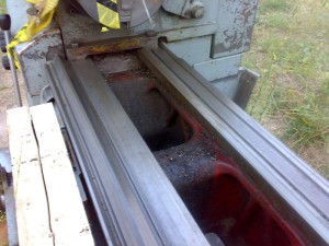
The deep risks and scuffs formed during the operation of the guides are sealed with babbitt. The area to be repaired is carefully cleaned, the edges are cut at an angle of 90 ° with a high surface roughness. The surface is degreased with acetone, gasoline or a solution of soda ash, heated, flux (zinc chloride) is applied and soldered with a massive (1.5 ... 2 kg) soldering iron.
These defects are also eliminated by metallization. To do this, after the implementation of the above preparatory operations, zinc or brass is sprayed onto the defective place by means of a metallizer. After spraying or soldering, the guides are ground or scraped.
If the repair of the beds is carried out by the workshop repair team, then it is not advisable to use special machines for machining the guides due to their low load.
When the guide beds are worn up to 0.12 mm, under these conditions, scraping or scraping with lapping with GOI paste is used. It should be noted that even with slight wear (up to 0.05 mm) of the guides, their restoration by scraping is characterized by significant labor intensity and cost, but low productivity. However, scraping ensures high accuracy of contact between mating surfaces (up to 30 spots on an area of 625 mm2). The scraping of the guides is carried out either without removing the frames from their foundation, or with removal from the foundation and installation on a slab or rigid concrete floor. After installing the frame, for example, a lathe, its guides are set in the longitudinal direction according to the level that is installed on the less worn parts of the horizontal guide along its entire length. The position of the frame in the transverse direction is checked with a frame level applied to the plane on which the feed box is attached. At the same time, skew is checked using a bridge or carriage (used as bridge and level). The bridge is located on different areas along the guides. Depending on the readings of the levels, the position of the bed is adjusted with shoes 14 ( rice. 1, b) or wedges 15 ( rice. 1, in), which are placed under its base or legs. It is convenient to align with jack bolts 16 ( rice. 1, g). By screwing or unscrewing the bolts, the frame is raised or lowered. The regulation is carried out until the bubble of the main ampoule of the level takes the zero position. This indicates the correct position of the bed.
After alignment of the frame, a base surface is selected, along which the parallelism of all guides to be restored is monitored. At the lathe bed ( rice. 1, a) for such a base, they usually take guides 3, 4 and 6, on which the tailstock is based. These guides during the operation of the machine wear out much less than others. These guides are first scraped in order to eliminate wear, periodically controlling the flatness and straightness by means of a control ruler. After that, the surfaces of 2, 7, 8 guides are scraped, checking their parallelism. It should be noted that, despite the slight wear of the guides 3, 4 and 6, their parallelism with respect to the planes for installing and fastening the machine feed box and fastening the lead screw and shaft is often violated. Deviations from parallelism increase with an increase in the number of machine repairs. Therefore, when assembling repaired machines, the time spent on fitting the feed box and the bracket of the lead screw and shaft increases, which is performed by hand scraping. To avoid this, you can use a more rational technology for restoring guides. In this case, sections 200 ... 300 mm long of surfaces 11 and 72 are taken as the base ( see fig. 1, a) that are wear-free and do not require pre-treatment like tailstock guides.
After preparing the base surfaces, surfaces 3, 4 and 6 are scraped over the paint ( see fig. 1, a), periodically controlling their parallelism and skew. Then surfaces 2, 7 and 8 are scraped, controlling the level of their skew, and the indicator is the parallelism of surfaces 7 and 8 with the base ones. Surfaces 1 and 10 are scraped last.
If there is an allowance on the surfaces to be scraped that exceeds that recommended by reference books, then planing, grinding or sawing is first performed, and then scraping. The type of scraper and the width of its cutting part are selected depending on the shape of the surface to be scraped. So, for preliminary, rough scraping (number of spots n = 4 ÷ 6 on an area of 625 mm 2), scrapers 20 ... 25 mm wide are used, semi-finishing (n = 8 ÷ 15) - 12 ... 16 mm wide, and for final, finishing (n = 20 ÷ 30) - 5 ... 10 mm wide. The angles of installation, sharpening and cutting during scraping are determined depending on the physical and mechanical properties of the material being processed.
The quality control of scraping is carried out by means of calibration rulers or plates, as well as for paint by the number of spots in a square with a side of 25 mm. As a paint, Prussian blue, lamp black, blue and other paints are used, which are diluted in engine oil.
Scrapers made of steels ShKh15, U12A, R6M5 are sharpened with corundum wheels with a grain size of not more than 25 and hardness CM1 or CM2, and scrapers equipped with hard alloy plates are sharpened with diamond wheels or silicon carbide wheels.
If the length of the guide exceeds the length of the calibration ruler, then the scraping is carried out along the beacons, namely: in the place of maximum wear of the guide, a platform (beacon) is scraped, and at a distance slightly less than the length of the calibration ruler, a second platform is scraped, which is in the same plane with the beacon. Measuring tiles of the same height are installed on these sites, and a ruler with a level is placed on them, or an optical control method is used. Further along the ruler, a section of the guide is scraped between the indicated sites and, moving sequentially to the adjacent section, the entire surface of the guide is scraped.
The scraping of guides with lapping with GOI pastes is carried out in the following sequence. First, rough scraping is performed, then the surface is washed with kerosene and dried with rags, after which the surface is covered thin layer paste, then the mating part is lapped with the replacement (washing with kerosene) of the paste when it darkens until the scratches disappear and the necessary support area is obtained.
When the guide beds are worn up to 0.03 mm, they are repaired by grinding or filing and scraping. Grinding provides high precision and low surface roughness of the guides. If the steel or cast-iron guides of the beds are hardened by high-frequency currents or riveted (by vibration rolling, etc.), then they are ground. The performance of grinding is several times higher than that of scraping. Grinding is performed on surface grinding or longitudinal planing and milling machines equipped with grinders. Grinding guides is often combined with scraping the mating surfaces of guide tables, calipers, carriages, sliders and other moving parts of the machine.
If the wear of the guides is within 0.3 ... 0.5 mm, then their repair is carried out by thin planing or filing, followed by scraping or grinding. Fine planing is preferred when repairing non-hardened rails. It provides high machining accuracy and surface roughness Ra = 0.32. It is performed with wide cutters equipped with VK6 or VK8 hard alloy plates with cutting edge. The use of cutters with a wide blade makes it easier to adjust the machine support according to the profile of the guide and allows you to reduce the number of working strokes when planing. Processing is carried out in several passes: first, two passes are made with a cutting depth of up to 0.1 mm, then three or four passes with a cutting depth of 0.03 ... 0.05 mm.
If the guides are worn more than 0.5 mm, they are repaired by planing or milling on longitudinal planing or longitudinal milling machines in several passes (roughing, and then finishing).
Planing of the bed guides can be carried out if its overall dimensions smaller sizes planer table. The bed is installed in the middle part of the table of the specified precision machine and slightly fixed. Then, by moving the table, they check for parallelism of the base surfaces of the surface 11 ( see fig. 1, a). The check is carried out with an indicator installed in the machine support. The deviation from parallelism must not exceed 0.04/1000 mm. The bed is fixed, test planing is carried out on any of the horizontal surfaces, for example surface 2, until wear is eliminated. Then, by means of a control ruler and a probe, the deviation of the surface from straightness A is determined, due to the error in the movement of the machine table and other reasons.
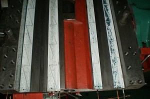
After that, the frame is artificially deformed with the help of bolts with nuts and tacks. Steel wedges 1 ( rice. 2, a, b), having a slope of 0°30"÷0°40" and a thickness of about 0.1 mm at the sharp end. Clamps in four sections A and B deform the frame being repaired in the vertical plane by the amount of deviation from straightness D, determined during trial planing. It is performed once; the obtained value A is taken as a constant during subsequent repairs of the beds different models similar length. If the deviation A is directed towards concavity ( rice. 2, a), then the bed is bent by ∆ + 0.02 mm in the same direction and the wear of the guides is eliminated by planing. After the end of processing, the fastening bolts are released, the clamps and wedges are removed. The bed springs, straightens, and its guides become straight. This is due to the fact that during processing at the ends of the bed a larger layer of metal is removed than in its middle. The deviation of the guides in the direction of the bulge is within the allowable specifications. In the case when the deviation A from straightness is directed towards the convexity ( rice. 2b), the frame is bent by means of the same means by a value of ∆ - 0.02 mm. After processing the bed guides and removing it from the machine table, the guides, as in the previous case, turn out to be with an acceptable technical requirements convexity 0.02/1000 mm.
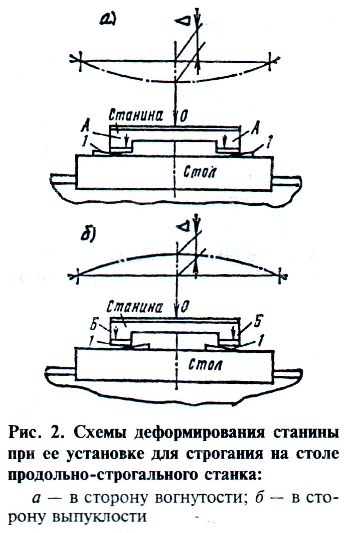
For the deflection of the frame in its middle part ( see fig 2, a) wedges are installed closer to the ends, and tacks closer to the middle, as shown by arrows A. To bend the bed in the middle part ( see fig. 2b) the wedges are set closer to the middle, and the tacks are closer to the edges, as shown by arrows B. The required amount of deflection or arching of the bed is provided by tightening the tack bolts and moving the wedges with light hammer blows. When performing this operation, the deformation of the frame is controlled by an indicator, the measuring rod of which is brought to point 0 - the place of maximum deformation. Finally, the accuracy of the position is checked when fixing the bolts. Plane surfaces 1, 2, 3, 4, 6, 7, 8, and 10 ( see fig. 2, a), eliminating their wear. Surfaces 11 and 12 are usually left untreated since they are not subject to wear. The accuracy of the guides after planing is checked with a universal level bridge.
To increase the wear resistance of the guides after machining, they are hardened with high-frequency currents or a gas flame, riveting with balls, vibro-rolling is carried out.
When repairing guides, the following method can be used. First, the guides are pre-machined by planing or milling. Then the surfaces of the guides are treated with electrocorundum powder with a grain size of 500 ... 800 microns in jet chambers at a certain pressure of compressed air and an angle of inclination of the abrasive jet to the surface of 45 ... 70 °, a distance from the nozzle to the last 20 ... 80 mm, air consumption 6 ...8 m 3 /min. Next, the surfaces of the guides are cleaned with compressed air, washed with an organic solution, followed by rinsing with a synthetic detergent and drying surfaces with compressed air. Then the guides are thermally sprayed with a wear-resistant self-fluxing mechanically alloyed powder, which includes the ingredients: carbon, chromium, nickel, manganese, boron, silicon, iron, which are in a certain percentage with a particle size of 40 ... 100 microns. For spraying, you can use the installations UPU-3, UPU-5, UPU-30, plasma-technician AG with dispensers. Spraying mode: current strength 400...500 A, voltage 50...45 V, spraying distance 80 mm, transport gas - argon or helium.
After deposition, slow cooling is performed in an asbestos "fur coat", then a layer absorbing laser radiation is applied to the deposition surfaces. Then the laser produces a continuous melting of the surfaces of the guides. After cooling, the coating is polished with diamond wheels of the ASKM, ASK, ASV grades with a grain size of 200/160, 250/200. The processing quality and coating thickness are controlled by means of beta-thickness gauges of the BTI-6, BTI-8 type. Next, a layer is applied that absorbs laser radiation, and the microrelief obtained after grinding is melted with a laser beam. Then the surfaces of the guides are cleaned with the Labomid-101 solution and the roughness, waviness are controlled (with a profilograph-profilometer model 201), as well as the geometric parameters of the guides.
The wear resistance of guides restored in this way (compared, for example, with hardened steel 45) is doubled. Melting of this powder coating with a laser beam gives an additional increase in wear resistance by 1.3...2 times compared to gas burner. The structure of the coatings after laser melting has a reduced tendency to seize under boundary lubrication conditions with varying specific loads and sliding speeds over a wide range, which are typical for most guide machines.
Application of finishing laser processing(micromelting of roughness and waves) reduces roughness by 1.5 ... 2.5 times, steps of irregularities - up to 4 times. As a result of reducing the waviness, the contact stiffness of the surface layer increases by 1.5...2 times, the running-in time of the guides decreases by 1.4...1.6 times.
In case of significant wear, the guides are repaired: by planing or milling, followed by the installation of overlays from getinaks B, vinylplast 10, textolite PT or PT-1, (overlays are glued BF-2, BF-4, epoxy glue); vortex spraying of polyamide (nylon, etc.); injection molding of styracryl; surfacing or metallization of metal alloys (brass LTS38Mts2S2, monel metal, zinc alloy TsAM 10-5).
Significant defects and heavy wear of the guides are eliminated by planing or milling or by installing overhead guides in their place and fixing them with bolts.
After restoring the guides, their geometric accuracy is checked using universal devices.
The complexity and efficiency of some methods of repair of guide beds
A. G. Skhirtladze
Magazine "Repair, restoration, modernization" No. 3, 2002
We also recommend
 Switching power supply: repair and refinement
 Remote control of light
 Swimming lessons for preschool children
 Notes for the master - home household alarms
 Clock propeller on Atmega8
 Device and relay application examples, how to choose and connect a relay correctly Microcontroller and relay simple switching circuits