Carousel 1516
The lathe, which replaced the frontal type devices and almost completely ousted them from the market, was designed for processing workpieces that are distinguished by an impressive diameter and weight, but having a small length.
Application and advantages of lathe-carousel machines
Using lathes, they are engaged in the processing of overall flywheels, gears and other similar parts. The technical capabilities of such devices allow you to perform the following technological operations:
- turning and boring of workpieces having a cylindrical and conical configuration;
- cutting ends and their processing;
- processing of surfaces of an inclined type;
- formation of ring-type grooves on the surface of the part;
- drilling;
- deployment;
- reaming.
Vertical lathes are also equipped with special devices, supplied separately, which allows you to perform the following operations on this equipment: milling, chiselling, threading different type, processing of shaped surfaces using an electrocopier, grinding, processing of workpieces using stops. The characteristics of vertical lathes make it possible to process workpieces made from ferrous and non-ferrous metals with a diameter of up to 25 m.
The main movement in the machines of the group under consideration is made by the desktop (faceplate), on which the part is fixed. The movement of the feed, as in all lathes, in the turning and rotary equipment is performed by the caliper.
The carousel machine, due to its design features, is distinguished by high safety, reliability, ease of maintenance and operation. Among the most significant advantages of such equipment, it is worth highlighting the following:
- accuracy and high quality of processing, assuming a minimum percentage of rejects;
- ease of equipment control, which is especially typical for machine tools equipped with a CNC system;
- high speed of execution of all technological operations.
However, as many experts note, the most important advantages that vertical lathes have is the safety of their operation.
How lathes are arranged
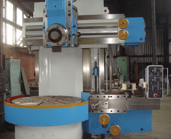
The most significant element of the design of the lathe-carousel group is their work table, on which the faceplate is placed. It is here that the workpiece that requires processing is fixed. The working surface of the table is located in a horizontal plane, which simplifies the process of installing workpieces with significant dimensions and weight on it.
Depending on the model and design features, among the machines of the turning and rotary group, one- and two-column ones are distinguished. On the first, a faceplate with a diameter of up to 1600 mm is installed. Such units are used to work with workpieces having a diameter of up to 1500 mm. Two-column units have more impressive characteristics, on which a faceplate with a diameter of up to 25000 mm can be installed, which makes it possible to process very large workpieces.
On the frame of a two-column unit, located in a vertical plane, there are two guides along which the cross member moves with two calipers mounted on it - a turret and a boring one. The calipers of the machine, in turn, move along the horizontal guides of the crossbar.
The turret caliper, which can move in vertical and horizontal directions, includes a longitudinal carriage and a slider moving along the vertical axis. It is mounted on the slider with special holes for installation cutting tool. With the help of a turret support and a cutting tool fixed in it, such technological operations as processing of external surfaces, drilling holes, cutting the ends of the part are performed.
The design of the boring caliper includes a longitudinal carriage on which is mounted rotary mechanism. The latter has a slider with a tool holder mounted on it. With the help of a boring caliper and tools fixed in it, the processing of conical surfaces, boring holes and cutting internal grooves are performed.
On single-column lathes of the turning-and-boring group, a side support is installed, consisting of a longitudinal carriage, a slider and a tool holder. The purpose of such a caliper is to ensure the processing of external surfaces.

The use of two cutting tools simultaneously in the machining process is especially important in the field of heavy engineering - in the production of hydraulic turbines, generators and other parts that are large in size and weight.
The main features of the equipment
When choosing a lathe-carousel group, the following characteristics should be taken into account:
- machine power;
- the number of speeds and the range of rotational speed of the faceplate;
- angle of rotation of the slider of the vertical support;
- the value of the maximum movement of the equipment supports in the horizontal and vertical directions;
- maximum dimensions of the workpiece to be processed (height, diameter);
- maximum value movement of the crossbar (for two-column machines);
- faceplate dimensions.
Processing on lathes of the turning and carousel group is carried out at high speeds. This is acceptable because the workpiece and the spindle do not experience significant cantilever loads, since the faceplate is fixed to the desktop in a special way.
In addition to the main movement and the feed movement, on the machines of this group, a crossbar is used (it is also called a traverse) additional movement. With its help, the cutting tool is brought to the surface of the workpiece being processed.
As mentioned above, the details large diameter(16.5–25 m) are processed on two-column lathes of the rotary-and-boring type, and single-column units are used for workpieces with smaller dimensions. CNC systems are installed on single-column carousel devices, which makes it possible to use such equipment for processing parts with a complex configuration, characterized by the presence of both rectilinear and curvilinear generatrices.
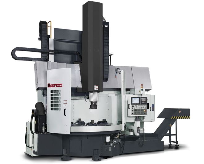
Tellingly, on lathes equipped with CNC, a side support is not installed: all technological operations on them are performed by using a turret support, the operation of which, like the drive of the main movement, is controlled by a special program. Entered into the control unit of the machine, it is responsible for performing such technological operations as:
- selection and installation of the required rotational speed of the equipment faceplate;
- turning the turret to the position required for processing, and fixing it in this position;
- control of the feeds made and the position occupied by the working devices;
- installation of the cutting tool in the zero position;
- control of the movements that the working tools make.
Models of domestic turning and rotary equipment
The history of domestic turning-and-boring machines began in 1935, when at the Krasnodar Machine-Tool Plant named after G.M. Gray hair was released the first such unit. It should be noted that this plant long time was considered the most famous and authoritative manufacturer of lathes of the carousel type. The plant's products - high-quality and reliable turning-and-boring machines - were actively used throughout the territory Soviet Union. Many of these devices can still be found in industrial enterprises.
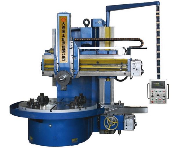
The most popular models of equipment from this manufacturer include machine 1516. This model of a single-column machine (along with model 1512) belongs to the category of universal turning and rotary devices designed for processing workpieces from ferrous and non-ferrous metals in conditions of small-scale and serial production.
The technical characteristics of the machines of both models mentioned above provide the performance of almost any turning operations, but these devices are used mainly for turning and boring:
- cylindrical surfaces;
- flat ends of blanks;
- conical surfaces.
You can find some modifications of these machines, on which the manufacturer installed self-centering type faceplates. Naturally, the technological capabilities of equipment with such faceplates are much wider than those of conventional models.
Produced at the plant named after G.M. Gray hair and two-column lathes of the turning and carousel group. Here, model 1525 is a striking example. Among the remarkable characteristics of the machine of this model, it is worth noting the following: the ability to change the direction of rotation of the faceplate (reverse); the presence in the design of two upper calipers of a rotary type. The drive of the main movement of the machine model 1525 was equipped with a two-stage gearbox and an electric motor, the shaft speed of which can be adjusted. Two electromagnetic clutches are responsible for choosing the range of the faceplate rotation speed in the design of the machine, and the rotational speed of the main motor shaft is steplessly regulated by means of a special electrical circuit.
All of the above models of machine tools were also produced with CNC, then their marking looked like this: 1512F2, 1516F2, 1525F2. Domestic software systems (P32-3M, H55-2) or electronic equipment from Bosch (Germany) and Alcatel (France) were installed as a control system on these devices.
Popular foreign machines of the turning and carousel group
Presented on the domestic market big choice turning and rotary equipment from foreign manufacturers. About the most popular models and trademarks should be mentioned separately.
A good value for money is demonstrated by machines from the Chinese company Dalian Guofeng Machine Tools, in the marking of which there is the letter "C".
5231, 5240, 5250, 52630These models belong to the category of turning and rotary equipment of two-column type, according to their technical specifications they are in many ways similar to the machines of the plant. G.M. Gray hair. These devices make it possible to carry out blanks with a sufficiently high accuracy, characterized by both simple and complex configurations.

Dalian Guofeng Machine Tools C5250 - machine tool from a Chinese manufacturer
5110, 5116, 5123, 5125, 5131These are single-column models of turning and rotary equipment, the power of which varies from 22 to 45 kW. On the units of these models, a simplified CNC system is installed - a digital indication, with the help of which the control of the operation of a vertical lathe becomes more convenient, simple and efficient. Equipped with additional servo motors for X and Z axis drives, these machines are also highly reliable and accurate in machining.
If we consider higher quality (and therefore more expensive) vertical turning equipment from foreign manufacturers, presented and popular on the domestic market, then it is worth noting the products of the Swiss company ENCE GmbH. This manufacturer offers equipment of several series.
Dalian Guofeng Machine Tools C5116
LEN 3000-5000
On the equipment of these models, workpieces are processed, the diameter of which is in the range of 315–500 cm. The CNC system is not installed on the machines of this series, but if necessary, they can be equipped with such a system very quickly. The two-stage drive, realizing the main movement, is equipped with an electric motor, the shaft speed of which can be changed in 16 steps. Two types of guides are used on these lathes: vertical - sliding, horizontal - hydrostatic type (they act as unloading elements).
LEN 1250-2000As is clear from the designation, parts with a diameter of 125–200 cm are processed on these devices. The units of this series are equipped with roller guides, in the moving units of which high-precision rolling bearings are installed. The vertical and four-position slides of these vertical lathes are hydraulically balanced, which improves machining accuracy. The reliability of the equipment of this series is also facilitated by the fact that it is equipped with electrical components from famous company Siemens.
SEN 1000-1800This is CNC-equipped turning and turning equipment from Siemens Fanuc. Among the important design features equipment of this series, it is worth highlighting a servomotor with a ZF gearbox (Germany) and a thermally symmetrical worktable. This equipment is produced, characterized by high speed processing and low noise, in three main categories: standard, heavy and high-precision.
The Russian vertical lathe 1516 is a high-quality and high-performance equipment. It can be used for turning workpieces with a diameter of up to 1600mm.
Model characteristics
The following operations are available:
- turning and boring of workpieces having the shape of a cylinder;
- trimming ends;
- groove cutting.
One of the main characteristics of a vertical lathe is the faceplate diameter. On the 1516 machine, the faceplate has a diameter of 1400mm and is capable of rotating in the range from 1 revolution to 200 revolutions per minute.
Additional features
When installing additional equipment the functionality of the lathe 1516 can be expanded, in particular, it is possible to carry out operations for threading, processing conical surfaces, as well as curved ones using a copier. Also, if desired, you can install a coolant supply device, as well as a self-centering faceplate.
On the model 1516 machine, it is possible to install either a digital indication system (DRO) or a CNC. In the first case, the machine will have the index "F1", in the second - "F3".
The Russtanko company offers you to purchase a 1516 vertical lathe at a reasonable price. You can discuss all questions on equipment configuration with our employees by phone or by sending an electronic application on the website.
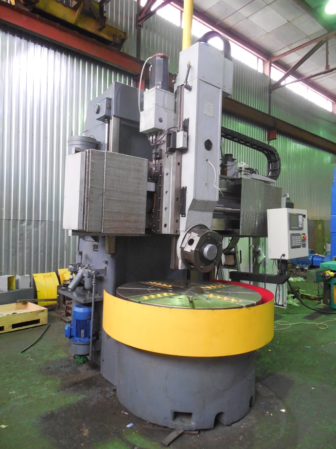
Vertical lathe - special kind metalworking equipment, which is designed to work with large workpieces of large diameter, whose weight is tens of tons. A feature of the design of such machines is the working table of a round shape. This specificity greatly simplifies the installation, alignment and fixation of the part.
Turning and rotary machines are necessary for turning surfaces of revolution using a special cutter. If the unit is equipped with a special turret, then the central holes in the part can be machined using drills, countersinks or other tools.
When choosing a turning and turning unit, the master needs to focus on such key characteristics as the maximum height and limiting diameter structure being processed. The main movement of the cutting part is carried out by rotating the work table, on which the workpiece is fixed.
To date, depending on the number of racks, one- and two-rack variations of carousel machines are distinguished. The units can be equipped with a manual control system or numerical control. In the second case, the machine can be involved in the processing of workpieces with a complex configuration. It is also used in factories and workshops where there is a need to process surfaces using curved and straight generatrixes, to cut non-standard threads And so on. The design difference of machines with program control is the absence of a side support in the first ones.

Turning and rotary industrial machine with numerical control capable of performing the operation of the program. Besides, program control means correcting the position of the cutting element. The program created by the operator independently changes the intensity of the spindle rotation, determines the feed, moves the tool. All this increases the productivity of the machine at times.
Consider two popular models - the unit 1516 and 1512, which are successful products of the Sedin Plant. This will help us understand the specifics of this technique.
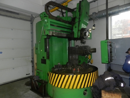
Vertical lathe 1516
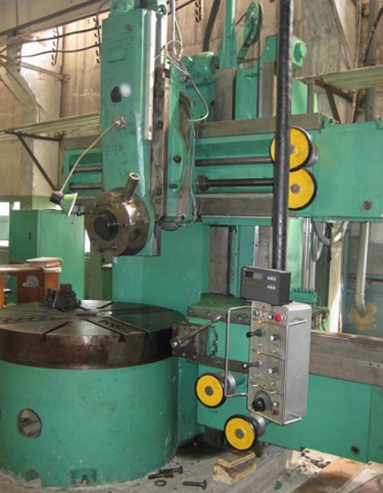
The 1516 vertical lathe is a single-column machine used for machining metal parts in small and large batch shops. This model boasts a wide range of operations, such as boring, turning, drilling and others. In addition, the machine is capable of finishing and semi-finishing turning.
The design of the 1516 vertical lathe includes vertical and horizontal calipers. The vertical caliper is equipped with a 5-position head equipped with an automatic rotation system. The horizontal support is equipped with a 4-position tool holder.
Even though the 1516 has a lot of functionality even in its basic version, the latter can be expanded with additional options, such as a self-centering faceplate, a cooling system, and highly specialized tools for threading and processing non-standard surfaces.

Unit 1516 is equipped with a powerful electric motor of the main drive, which is its important advantage. Among the advantages it is also worth noting:
- Excellent rigidity of the main parts of the unit, which ensures the most accurate processing of the workpiece.
- Reliability constituent parts kinematic chain.
- Possibility of regulation of frequency of turns of a faceplate in a wide range.
- Choice of feed rates for efficient cutting at high speeds.
Let's mention the key characteristics of the model 1516:
- The maximum diameter of the workpiece is 160 cm;
- Permissible product height - 100 cm;
- Faceplate diameter - 140 cm;
- Number of speeds - 18 gears;
- Faceplate rotation range - 5-250 mm;
- Electric motor power - 30 kW;
- Unit dimensions - 3170x3030x4100 mm;
- Weight - 20 tons.
Turning and carousel model 1512
Since the design of the 1512 lathe is similar in many ways to the 1516 model, it makes sense to consider only those machine parameters that differ from the 1516 characteristics. Let's present them in the form of a list:
- Permissible workpiece diameter - 125 cm;
- The maximum height of the product is 100 cm;
- Faceplate diameter - 112 cm;
- Dimensions - 2750x2975x4100 mm;
- Weight - 16.5 tons.
For all other parameters lathe 1512 is identical to model 1516.
Results
Vertical lathes are indispensable assistants that can perform tasks that a traditional lathe cannot handle. If you have to work with large-scale workpieces of large diameter, you cannot do without these machines.
The choice in favor of models 1512 and 1516 is the confidence in the long-term operation of the machine without any problems. This is confirmed by many years of experience in the use of units of the Sedin Machine-Tool Plant throughout the CIS.
Single-column lathes 1512 and 1516 are universal machines and are designed for processing a variety of products from ferrous and non-ferrous metals in small-scale and mass production
The machine can perform the following operations:
turning cylindrical and conical surfaces;
boring of cylindrical and conical surfaces;
Turning flat end surfaces with top and side calipers. In addition, the upper caliper can be used to grind flat end surfaces while maintaining a stepped-constant cutting speed in semi-finishing modes;
drilling, reaming and reaming; grooving and trimming.
When using special devices and devices that are supplied with the machines by special order and for a fee, the machines can be used to:
processing of parts according to specified dimensions (on stops);
threading, turning and boring of conical surfaces;
processing of shaped surfaces of bodies of revolution along a copier (electrocopier); processing of parts with cooling.
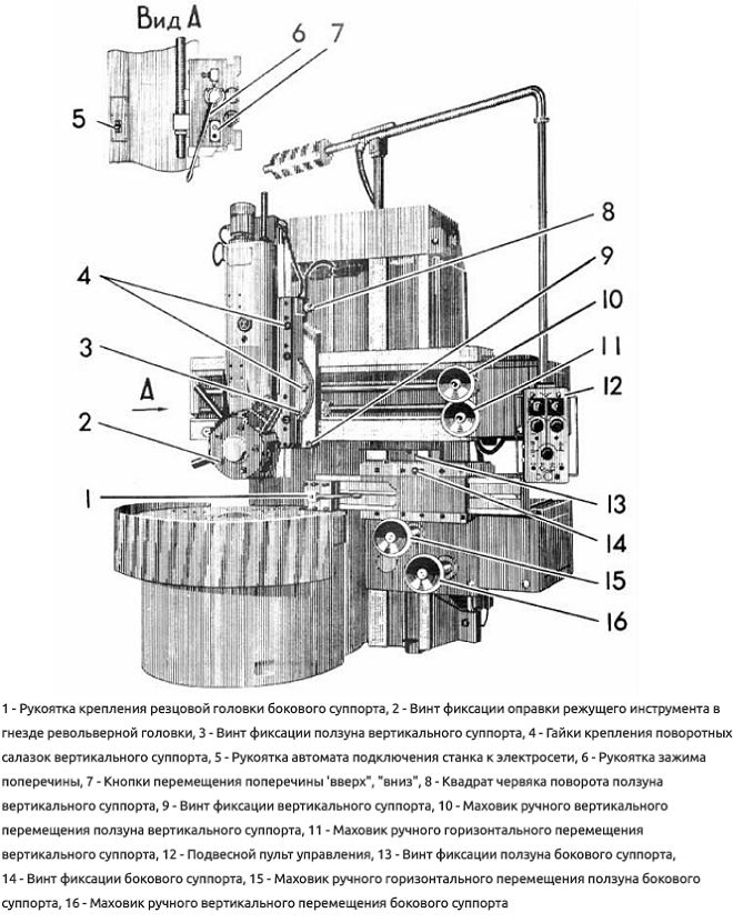
In the usual version, the machines are supplied with an upper turret with mechanical rotation and clamping of the turret, and with a side turret.
Kinematic scheme
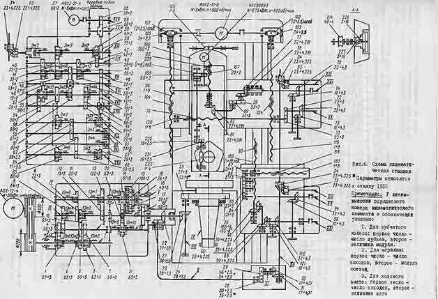
The kinematic schemes of the machines 1512 and 1516 are similar to each other and differ from each other only in the kinematics of the chain of the mechanism for transmitting movement to the feed and the number of teeth of the gears of the table.
Due to different number teeth of gears 25, 26 of the table, machines 1512 and 1516, with the same gearbox, have different limits for the speed of the faceplate.
The kinematics of the chains of the mechanism for transmitting movement to feed are different for the machines, but their gear ratios are selected in such a way that the total gear ratio of the kinematic chain from the faceplate to the feed box is the same for both machines. This allows you to use the same feed boxes and get the same feed rates.
The kinematic chains of the table, the crossbar and its movement mechanism, the upper and side supports are simple and self-explanatory.
bed
The bed serves as the basis for all the components of the machine, ensuring their movement and correct mutual arrangement. It perceives efforts from cutting forces and the mass of its constituent parts. The bed is a hollow casting, reinforced inside with stiffeners, so that with a relatively small mass it has sufficient strength and rigidity. A table with a faceplate is attached to the bed in front.
The table and the bed are connected with pins, which provide greater rigidity of the joint and vibration-free operation of the machine, which is necessary to obtain high precision of the machined parts.
On the front side of the frame there are guides along which the cross member and side support move. On the right, the body of the mechanism for transmitting motion to the feed is attached to the frame, and on top - the mechanism for moving the crossbar.
A gearbox is inserted inside the frame. The lower internal cavity of the frame is used as an oil reservoir that feeds centralized system gear box and table lubrication.
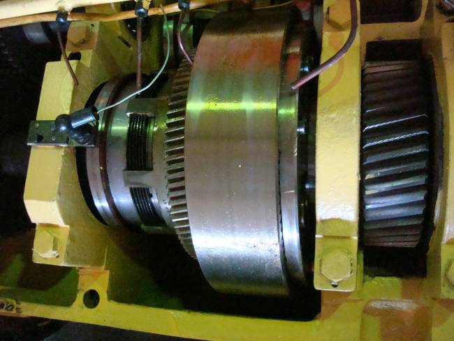
Gearbox
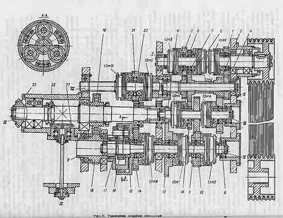
The gearbox is used to ensure the rotation of the faceplate, as well as to start, stop and change the speed. Rotation to the input shaft of the gearbox is transmitted from the main drive electric motor through a V-belt drive. The gearbox informs the faceplate of 18 speed steps.
Control of a box of speeds - remote from the suspended panel.
The presence of electromagnetic clutches in the gearbox allows you to switch speeds on the go and thereby ensure the maintenance of a stepped-constant cutting speed when machining end surfaces.
The gearbox has six shafts mounted on rolling bearings in a housing with a parting plane along the axes of the shafts XY and y for ease of assembly.
At a higher speed, the start is carried out stepwise in two, three or pin stages. The number of stages of acceleration increases with the increase in the frequency of rotation of the faceplate.
Clutch switching during step acceleration is carried out automatically
Changing the speed from stage I to stage II is carried out by switching on the corresponding combinations of electromagnetic clutches. At the same time, the 1Em8 clutch is turned off and the gear ratio of the planetary mechanism is 1/4 (1Em9 and 1EM10 clutches are on). When 13-18 speed steps are turned on, the faceplates of the 1Em9 and 1EM10 clutches are turned off, and the 1Em8 clutch is turned on and the gear ratio of the planetary mechanism in this case is equal to I
To enable the jog operation of the faceplate, used when installing and aligning the part, it is necessary to set the switch on the pendant control to the "Jog start" position of the faceplate and press the Start button of the faceplate.
There are no special braking devices in the gearbox, and the faceplate is braked by simultaneously switching on several electromagnetic clutches that close two different kinematic circuits that form a "lock". The remaining clutches of the gearbox are switched off. The deceleration time of the faceplate depends on the rotational speed and the weight of the workpiece. Approximate time for stopping the rotation of the faceplate after the start of braking is from 2 to 10 s.
To ensure simultaneous engagement of the gear wheels 15, 16, 17 of the planetary mechanism, the gear wheel 16 is connected to the shaft 1U by means of a gear coupling, which makes it possible for them to self-align.
In the gearbox, helical gears ensure smooth gearing at high circumferential speeds. All gears are in constant mesh.
When switching speeds on the go, shocks and slowdowns in the rotation of the faceplate are possible, which does not affect the operation of the machine and is not a malfunction.
Lubrication is carried out from a separate gear pump, heated on the side wall of the frame. Oil is supplied through tubes to all working elements.
The voltage supply to the contact rings of rotating electromagnetic clutches is carried out by brushes mounted on special brackets.
Table
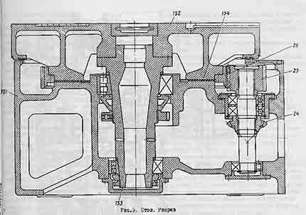
On fig. the table of the machine 1516 is shown. There are no fundamental structural differences between the tables of the machines 1516 and 1512. Machine parts are similar and differ from each other only in size.
The table consists of a body 151 having circular guides, a faceplate 152 with a spindle 153 and a faceplate drive.
The body of the table is a cast iron casting with a developed system of ribs, giving it great rigidity.
In the upper part of the table body there are annular protrusions that enter the annular grooves of the faceplate forming a labyrinth. This prevents splashing of lubricant and protects against chips, cast iron dust, emulsion and other contaminants entering the table.
The drive of the faceplate is carried out from the gearbox through a pair of bevel gears with a circular tooth 23 of the gearbox and 24 table further through a cylindrical pair: gear 25 and crown gear 26 rigidly connected to the faceplate.
To ensure smooth operation at a significant speed of the machines, the gears of the faceplate drive are made helical, and the bevel gears are made with a circular tooth.
The faceplate is a hollow disk with a number of internal radial and annular rabers.
On the upper plane there are T-shaped machine slots, which serve to fix the clamping jaws, various fixtures or to directly clamp the workpieces.
For precise installation of parts or mounting devices in the center of the faceplate, a centering hole is bored in the faceplate, which is protected from nicks by a special plug.
The basic version of the machine comes with four jaws for clamping workpieces. Each cam has independent movement.
Gearbox
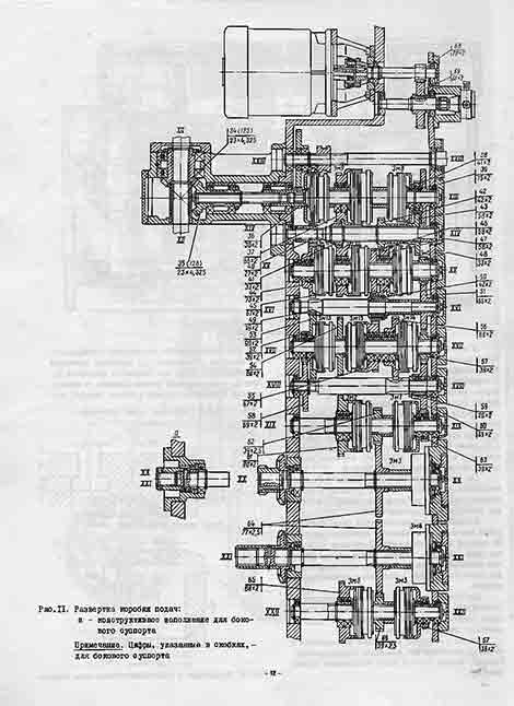
The design of the feed boxes of the side and upper calipers is the same.
Gearbox upper caliper mounted on the right end of the crossbar; side caliper feed box - directly to its body.
The body of the feed box is cast iron. a box-shaped casting with sufficient rigidity. All shafts of the feed box are mounted on rolling bearings.
The drive of the feed boxes is carried out from the vertical splined shaft HP, which receives rotation from the output shaft U1 of the gearbox through the mechanism for transferring movement to the feed. The feed boxes tell the calipers 18 working feeds (mm / rev.) And 18 speeds of installation movements (mm / min). This is achieved by the inclusion of appropriate combinations of electromagnetic clutches of the feed boxes.
All gears of the feed boxes are in constant mesh.
Clutch Em7 of the XSh shaft is used to turn on the working feeds. When it is turned on, a kinematic connection is made between the vertical shaft of the mechanism for transmitting movement to the feed and the feed box. When this clutch is turned off, it is possible to turn on the installation movements of the caliper from a separate electric motor attached to the feed box body.
Depending on the required feed direction - right, left, up, down - respectively, one of the four direction clutches Em1, Em2, Em5, EMZ is turned on and one of the output shafts XX or XXI receives rotation in the selected direction.
Brake clutches Em3, Em4 on shafts XX and XXI serve to dampen the inertia of the calipers and eliminate overruns.
The use of electromagnetic clutches provides remote control: turning on and off working feeds and installation movements, as well as selecting and switching feeds on the go from the pendant control panel.
Crossbar and crossbar movement mechanism
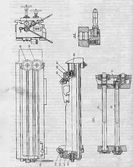
The crossbar is placed on the vertical guides of the frame. The body of the crossbar is a casting, the cross section of which has horizontal rectangular guides along which the upper caliper moves.
Between the horizontal guides in the niche are the running shaft 119 and the running screw 120, which are mounted on rolling bearings located in the bores of the cross members.
The crossbar has a vertical installation movement along the guides of the frame, carried out by the mechanism for moving the crossbar using two screws 116 and nuts 104 rigidly connected to the crossbar.
The mechanism for moving the crossbar is located on the upper plane of the frame and consists of two worm gears driven by a separate reversible electric motor. Gear coupling II7, consisting of coupling halves and connecting the motor shaft with shaft 118, serves to install the crossbar parallel to the working surface of the faceplate. By turning the coupling half by one tooth, the cross member moves by 0.005 mm.
The crossbar can be installed on the bed guides at different heights within its stroke. At the same time, it is securely fixed by hand with a special clamping mechanism.
The movement of the crossbar is interlocked with the clamping mechanism so that when the crossbar is clamped, its movement does not turn on.
The buttons for moving the crossbar "Up" and "Down" are located on the left end of the crossbar under the handle of the crossbar clamp mechanism.
To move the crossbar, the clamping handle 165 is retracted to the right. When you press the "Up" or "Down" button, the crossbar starts to move. The movement lasts as long as the button is pressed or until the crossbar reaches its end position and presses one of the limit switches that limit its movement.
At the end of the movement, the clamping of the cross member on the non-guiding racks is carried out by turning the handle to the left.
To ensure a stable position of the crossbar when it is lowered and to select the gaps, the electrical circuit is designed so that when the button is released, the electric motor is reversed, and the crossbar is automatically raised, after which the electric motor is turned off.
To prevent the cross member from falling in case of accidental shearing of the turns of the main nut 104, there is a steel catch nut that catches the cross member.
Upper caliper
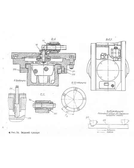
The upper caliper consists of: the lower part - a cross slide 196 moving along the horizontal guides of the cross member; upper rotary part - rotary slide 197, slider 198 with a turret moving in the guide rotary slide; mechanisms for driving the movement of the caliper and slider, turning and fixing the turret.
The cross slide is made in the form of a plate.
On the rear side, the slide has flat guides, the shape and dimensions of which correspond to the front guides of the crossbar.
Planks 199, 200 and wedges 201, 202 mounted on the rear side of the cross slide hold them on the cross rails. With the help of wedges, the gap between the guides and the slats, which occurs during the operation of the machine, is regulated. In addition, two unloaders are installed to select the gap between the lower cross member guide and the slide, as well as to reduce wear of the middle guide and facilitate the movement of the caliper. Roller 203, mounted on a needle bearing, rolls along the top rail of the cross member. Belleville springs 204 pull the caliper up, while unloading the crossbar guide by about 3/4 of its mass.
On the front plane of the cross slide there are circular T-slots, which include bolts 224 for fastening the rotary slide.
The swivel sled can be rotated 45° to one side or the other. The rotation is carried out manually with the help of a worm 105, warmed on the rotary slide, and a gear sector, the teeth of which are cut on the periphery of the cross slide.
The horizontal movement of the caliper along the cross-beams directed to them is carried out with the help of a lead screw 120 and a nut 76 rigidly connected to the caliper. The lead screw receives rotation from the output shaft XX of the feed box. Nut 76 consists of two halves, one of which 76a is fixed relative to the caliper, and the other 76b has the possibility of axial movement, which allows you to adjust the gap in threaded connection if the nut is worn.
Horizontal caliper (side)
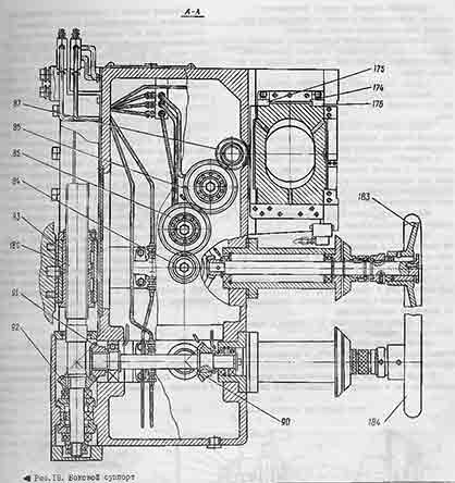
The side support consists of a body 170, a slider 171 and motion drive mechanisms.
The body of the side support is a cast iron box-shaped casting, reinforced with internal walls and stiffeners.
The movement drive mechanisms are located in the body. On the rear side, the body has guides for vertical movement of the caliper along the guides of the frame, and on the front, guides for moving the slider.
The guides have bronze linings that increase their wear resistance.
The caliper is held on the guides of the bed by a strap 172 and a wedge 173, which makes it possible to adjust the gap and compensate for the wear of the guides.
The slider is held on the guides by an overhead strap 174 and wedges 175, 176.
The movements of the caliper in the slider are limited by limit switches.
To protect guides from chips and dust
protective scrapers installed.
The side caliper is fastened to the bed rails with screw 177, and the slider on the caliper rails is screwed 178.
The slider and caliper can be moved both mechanically and manually by flywheels 183 and 164.
Working feeds and installation movements are reported to the caliper by the feed box. The movement of the output shaft XXI of the feed box (vertical movement) is transmitted to the caliper shaft 179, then through two pairs of bevel gears 89 and 90,
91 and 92 on lead screw 180.
The lead screw nut is rigidly connected to the frame. The design of the nut provides for the possibility of adjusting it to compensate for wear and select gaps.
With horizontal movement, the movement from the output shaft XX of the feed box is transmitted to the support shaft 181 and then through two pairs of cylindrical gears 84, 85 and 86, 87 to a pair of screw-nut 182-88. The lead screw nut is rigidly connected to the slider. The design of the nut provides the possibility of choosing gaps during operation.
The slider of the side support has a four-sided rotary tool holder 195, which is seated on a pin 191 rigidly connected to the slider.
In the working position, the tool holder is securely fixed by flat gear couplings 192 and 193.
For one-sided clearance and lightening manual movement the caliper and the feed box fastened to it are balanced by a load that is placed in the internal cavity of the frame. The side support is connected to the load by a steel rope passing through the guide rollers.
Wiring diagram
Carousel lathes are designed for processing workpieces of large mass and diameter with a relatively small length. To do this, the spindle of the machine is located vertically - its upper end is connected to the plan-washer, to which the workpiece is attached (for fastening, the plan-washer has radially sliding cams).
The 1516 rotary machine allows you to perform all the machining operations typical for the equipment of the turning group: turning surfaces, boring, drilling, reaming holes, processing conical and cylindrical elements (both outside and inside the workpiece), etc.
Overhaul of machines 1516
Overhauling a lathe is an acceptable alternative to buying new equipment. During the overhaul, there is a complete restoration of the characteristics of the lathe, originally incorporated into its design by the manufacturer. At the same time, the cost of a major overhaul turns out to be an order of magnitude less than the price of new equipment (taking into account the fact that many machines have already been discontinued, they cannot be purchased new, and imported analogues are very expensive!).
Our company carries out overhaul machine tools various types. High quality work is determined by the availability of the necessary technological capacities - since the repair is carried out in a factory using modern materials and solutions.
In the process of overhaul of the lathe 1516, the following operations are carried out: . complete disassembly of the machine (including detailed disassembly of units and assemblies);
Thorough troubleshooting (determining the list of parts to be replaced / restored);
Correction of machine geometry (including grinding of bed guides);
Replacement of a screw pair of cross feed;
Complete replacement of all rubber products (RTI), as well as felt seals, dirt cleaners, etc.;
Careful revision of the headstock (if necessary, grinding of the spindle cone);
Replacement of all bearing units;
Replacement of toothed gears in gearboxes;
Revision of the caliper assembly;
Repair of the feed box and apron;
Evaluation of the tailstock (if necessary - grinding the quill cone or installing a new one);
Replacement of power lines, conductor connections and other elements of the electrical circuit;
At the end repair work all body parts of the machine are painted.
Then the equipment goes through a test cycle (according to the manufacturer's specifications).
At the request of customers, we install on a lathe frequency converter. This eliminates the need for a gearbox. This reduces the energy costs for the gear drive and friction losses, which means it increases the energy efficiency of the equipment. An additional plus: the frequency converter allows you to steplessly change the spindle speed with a very small step.
We guarantee the quality of the refurbished equipment and the compliance of the refurbished 1516 vertical lathe with all precision requirements. As well as the expansion of its technological capabilities through the use of modern parts, assemblies and CNC electrical control systems in the repair process.

We also recommend
 Switching power supply: repair and refinement
 Remote control of light
 Swimming lessons for preschool children
 Notes for the master - home household alarms
 Clock propeller on Atmega8
 Device and relay application examples, how to choose and connect a relay correctly Microcontroller and relay simple switching circuits