Legs for hi end amplifier drawings. Tube Audio Power Amplifier
We are all creators and artists to some extent, and we will not regret anything for ourselves. But there is not always time and, most importantly, desire to understand complex technical structures. Therefore, we usually skip this unpleasant procedure and hope for the decency of the brand. However, in modern reality, not all gold has a luster and it is possible to obtain low-valence bronze.
Amplifying Hi-End Audio equipment is a separate class of products that is difficult to evaluate with money, since the general sound set, along with the amplifier, includes speaker systems and a source of sound vibrations.
Quite obviously, the audio signal amplifier is an integral part of the overall sound amplifying system and its negative contribution to sound reproduction can always be attributed to a bad environment.
Many dealers of well-known companies (offering their products) immediately warn - very expensive Hi-end amplifier power works well only with recommended and very expensive speakers and wires. Therefore, when purchasing a high-quality device, it is difficult to assess its real potential, since 50% of the sound quality depends on the listening room and the psycho-emotional state of a person, which is controlled by a competent salesperson-psychologist.
We initially feel delighted with a new and expensive purchase, but in the future, the feeling of addiction gives rise to dissatisfaction, as an alternative thing has appeared nearby, which is, as it were, a little better. This is the line on the basis of which the entire advertising company is built (the sale of expensive audio equipment). And a person who finds himself in such a situation is a hostage and a potential buyer of exactly the same (in terms of sound amplification quality) only with a different equipment logo - you think / bought a new one / in a real comparison it turned out to be worse than the old one.
In the last century, the vacuum tube and its accompanying passive elements - capacitors and resistors - were "born".
A lamp is an active vacuum amplifying element that has a certain level of signal amplification (gain). A transistor is a semiconductor analogue of a lamp.
A resistor is a passive element that limits signal gain and currents by creating a voltage drop (working point) at the input and output of the lamp.
Capacitor - a passive element that transmits an audio signal and cuts off direct current, as well as filtering and maintaining the amplitude of direct voltage. However, when the power supply is turned on, a significant capacity of storage capacitors will provoke a current surge, which creates additional circuitry problems -.
For the lamp to work, you need to apply a constant voltage to the anode and use the cathode or anode resistor to adjust the desired signal amplification. That's it - the design is ready, this is a single-cycle class "A" preamplifier. It remains only to make a power supply - install a power transformer, rectifier diodes, a filter capacitor.
In the same way, we assemble the final amplification stage on a more powerful lamp, replacing the cathode resistor with an output transformer, we get a very simple and reliable circuit with the right sound. Unfortunately, mass production of such a product is commercially unprofitable, since the low output power and expensive audiophile parts, without which the amplifier will not produce a decent sound, will not make it possible to put money in your pocket.
Considering Hi-end amplifier as a whole, it turns out that all elements of the circuit are closely interconnected and the absence of one of them will lead to a violation of energy processes.
It is clear - each new detail affects the sound by adding its own negative overtones. And if there is no detail, then there is no problem. Therefore, the minimum number of passive components improves the sound quality, and the real noise is introduced by energy resource limiters - resistors. Resistors are difficult, but possible to replace with active elements that act on each other in a coordinated manner (one enhances, the other stabilizes the current supply), this compensates for the general negative overtones.
The decision to install cheap resistors or more expensive active elements is made not by the designer, but by the marketer. In the bottom line, morality wins - "the cheaper, the better." Unfortunately, this principle is progressing and leads to a reduction in the production of audiophile parts. Meanwhile, the Chinese occupy a free niche and drive consumer goods, and we begin to remember what sound was before, for normal money.
The power amplifier power supply provides energy to the active elements of the circuit by converting and filtering AC voltage to DC. The voltage conversion rate depends on the speed of the power rectifiers - diodes and has a great effect on the nature of the sound reproduction. Naturally, the use of high-speed diodes is necessary, but their cost depends on the power and speed.
Usually, manufacturers do not "steam" with diodes and install the cheapest current and voltage that are suitable for the nominal value, which does not allow the active elements of the circuit to fully realize their potential. The cost of diodes is from 1 ruble to $50.
The photo shows expensive and worthy diodes in all technical and not only parameters, based on silicon carbide, the price is $ 25 per 1 piece. Naturally, they are not in serial Hi End products.

An important element of the power supply is the capacitor, as it provides an instantaneous supply of pulsed energy to the amplifying element, which allows you to reproduce steep signal fronts - musical expression. Capacitors are divided into electrolytic, film and paper.
(electrolytes) have small dimensions, large capacities and a penny cost, their work is carried out using slow ionic processes, and their sound is clamped and inexpressive.

The photo shows high-quality and relatively expensive low-impedance electrolytic capacitors, which are also used in computer motherboards and video cards.
Separately, we note Sanyo OS-CON capacitors (purple) are installed in video accelerators of the most prestigious computer companies (dry separator - silver-coated paper), these are the best electrolytic capacitors for suppressing RF interference in digital circuits. Disadvantages - small denominations of capacities and high cost.
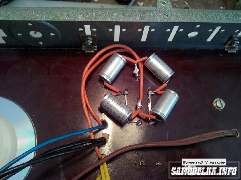
Film and paper capacitors have high impulse responses, a wide operating frequency range, low equivalent resistance, their sound character depends not only on the conductor and dielectric, but also on individual characteristics - the complexity of the manufacturing process, which guarantees a very high cost of audiophile film capacitors, which can reach tens or even hundreds of dollars. However, in serial Hi-End power amplifiers there are no such capacitors and cannot be, this confirms the same type of sound of amplifiers of different price categories and their official circuits.
It is quite obvious that a capacitor in audio is a matter of direct speculation, as there are many price points (walrus) on the market from 0.01 cents to $500 (and more). It is the cost of capacitors that determines the cost of an audio design in relation to the sound quality (price / sound quality).
If a well-known manufacturer of Hi-End amplifying equipment installs only a pair of capacitors worth $10 per unit, then the dealer has a real opportunity to sell the amplifier at the price of an expensive car. Therefore, in modern audio production, it is difficult to imagine the existence of a Hi-End amplifier with capacitors with a total cost of about $ 200.
As a result of the huge advertising costs and the greed of the manufacturer - dealer, the sound quality of modern audio products is at the level of the cost of capacitors and does not depend on the retail price of the device, and on brand awareness.
To be specific - you bought an expensive unit with a sound amplification level of $200, and the remaining thousands of dollars went to pay for advertising the brand's label.
That is why among many lovers of high-quality sound there is a prodigal opinion - all Hi-end amplifiers approximately the same and priority in sound amplification is given to connecting wires, source and speaker systems, forgetting for what purposes the audio equipment is used and who really amplifies the sound.

Audiophile film and paper capacitors worth $2000.
As a result of the use of inert electrolytes, the consumer (unknowingly) is looking not for equipment and sound quality, but for audiophile capacitors. But, by installing unique capacitors in a "branded" product, you will not get anything good, except for a new headache. The fact is that the general circuitry is tailored for the installation of cheap and huge capacitances of electrolytes, and paper-film capacitors have small capacitances and large dimensions. Therefore, a complete upgrade may require a symbolic amount, much more than a million dollars, and the case will turn into a closet. Now we have come to the answer to the question why manufacturers do not install high-quality paper and film?

The cost of four film capacitors (one white in the photo) is equal to the price of all electrolytic capacitors. From this number of electrolytic capacitors, more than 15 very expensive Hi-End amplifiers can be made. You can't even make one preliminary amplification channel out of four film capacitors.
In our single-ended hybrid power amplifiers, all stages operate on paper-film capacitors, and relatively large (by capacitance rating) electrolytic capacitors are installed only in a single place - a separate power supply for powerful output bipolar transistors, which determines the originality of circuitry.
The fact is that a small-capacity power supply technology of our own design (VIRTUAL BATTERY POWER SUPPLY) is used, where the capacity of paper and film capacitors is increased electronically. And the sound of such an amplifier, even on recordings from a mobile phone, makes an indelible impression, while the design works quite well in any room, with any speaker systems.
The total cost of all capacitors is $2000.
But the fun begins now!
- who are interested in the details, follow the link, and we will immediately go to the money. The cost of different types of these devices starts from 20 rubles and ends with a really unique $ 10,000, probably there are more expensive ones.
Handsome men in the photo for $ 200 - very cool for a modern Hi-End product.
Sellers of an amplifier of a well-known brand, in which such a mechanism is installed, can easily request 1/2 of the cost of an apartment, and this will be fine.
Easier - the hut is visible in this picture. This is what the life-giving speculator does (Ivan Baryga).

Frankly speaking, it makes no sense to install a volume control of this class in a modern expensive device, because the sound quality will change little (checked many times). This is due to the low sensitivity of the circuit to the quality of the electrical components used, since multiple feedbacks and numerous resistors really limit the speed of energy transfer, the classic "Uncle Ohm" conduction law works - more resistance less current, i.e. the energy supply per unit of time is reduced and additional resistance is created for its movement. As a way out - the rejection of the use of resistors and general feedbacks, but for this you need to turn on your head, which is difficult. That's why it's always easier to roll up a circuit from a textbook and introduce additional local feedback for exclusivity - this is new and modern technologies in Hi-End amplifiers.
To prove the above, we offer - to test the serial amplifier "Grimmi" on your terms, with any of the most expensive Hi-End amplifier. According to the results of the test, we will post candid video files, so that everyone can hear and see who really makes the sound, and who releases expired waste products.
Doubters, carefully watch the video files, there is a sound signature of the "Grimmi" amplifier and compare the quality of the (very compressed) recording with your very best originals, all doubts will be dispelled at once.
Today we have a useful homemade product for connoisseurs of good sound: a high-quality do-it-yourself tube amplifier
Hello!
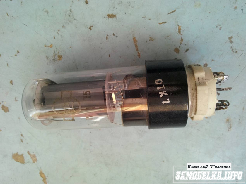
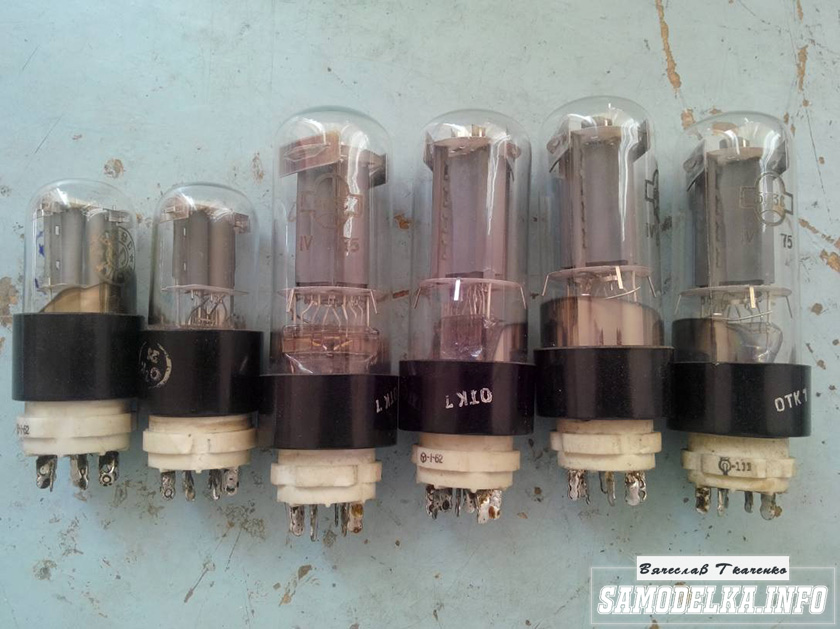
I decided to assemble a push-pull tube amplifier (my hands itch very much) from the parts that I have accumulated over a long long time: case, lamps, panels for them, transformers and so on.
I must say that I got all this stuff for free (tobish free of charge) and the cost of my new project will be 0.00 hryvnia, and if I need to buy something in small things, I’ll buy it for rubles (since I started my project in Ukraine, and I’ll finish already in Russia).
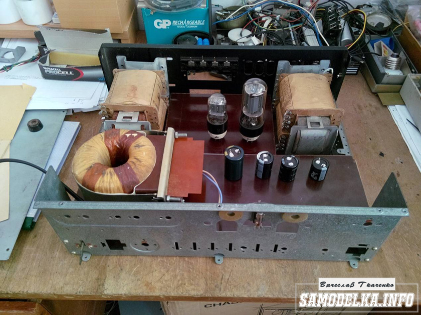
I'll start with the body.
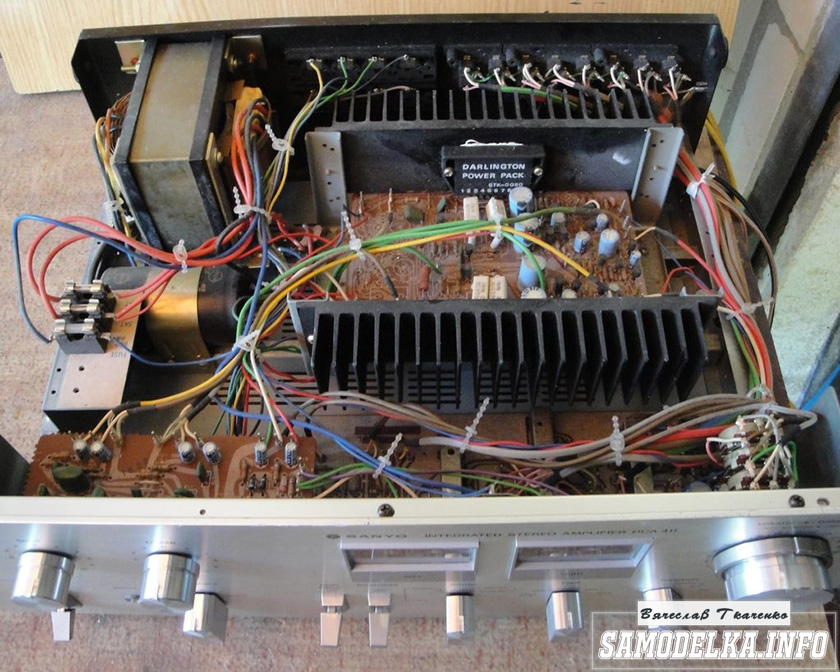
Once upon a time it was, apparently, a good SANYO DCA 411 amplifier.
But I didn’t have a chance to listen to him, because I got it in a terrible dirty and non-working form, it was dug up to the point of being impossible and the burnt 110 V networker (Japanese, probably) smoked all the insides. Instead of native microcircuits of the final stage, some snot from Soviet transistors (this is a photo from the Internet of a good copy). In short, I gutted it all, and began to think. So, I didn’t come up with anything better than to shove a lampovik there (there is quite a lot of space there).

Decision is made. Now we need to decide on the scheme and details. I have enough lamps 6p3s and 6n9s.

Due to the fact that I already assembled a single-cycle 6p3s, I wanted more power and, after rummaging through the Internet, I chose this 6p3s push-pull amplifier circuit.
Diagram of a homemade tube amplifier (ULF)
The scheme is taken from the site heavil.ru
I must say that the scheme is probably not the best, but in view of its relative simplicity and availability of parts, I decided to dwell on it. Output transformer (an important figure in the plot).
It was decided to use the "legendary" TC-180 as output transformers. Do not throw stones right away (save them until the end of the article :)) I myself have deep doubts about such a decision, but given my desire not to spend a penny on this project, I will continue.

I connected the trance conclusions for my case like this.
(8)—(7)(6)—(5)(2)—(1)(1′)—(2′)(5′)—(6′)(7′)—(8′) primary
(10)—(9)(9′)—(10′) secondary
anode voltage is applied to the connection of terminals 1 and 1', 8 and 8' to the anodes of the lamps.
10 and 10′ per speaker. (I did not come up with this myself, I found it on the Internet). To dispel the fog of pessimism, I decided to check the frequency response of the transformer by eye. To do this, I assembled such a stand in haste.

In the photo, the GZ-102 generator, the BEAG APT-100 amplifier (100V-100W), the C1-65 oscilloscope, the load equivalent of 4 ohms (100W), and the transformer itself. By the way, the site has.
I set 1000 Hz with a swing of 80 (approximately) volts and fix the voltage on the oscilloscope screen (about 2 V). Then I increase the frequency and wait for the voltage on the secondary of the trance to begin to drop. I do the same in the direction of decreasing the frequency.
The result, I must say, pleased me. The frequency response is almost linear in the range from 30 Hz to 16 kHz, well, I thought it would be much worse. By the way, the BEAG APT-100 amplifier has a step-up transformer at the output and its frequency response may not be ideal either.
Now you can collect everything to the heap in the case with a clear conscience. There is an idea to make the installation and layout inside in the best traditions of the so-called modding (minimum wires in sight) and it would not be bad to make the backlight with LEDs as in industrial copies.
Power supply for a homemade tube amplifier.
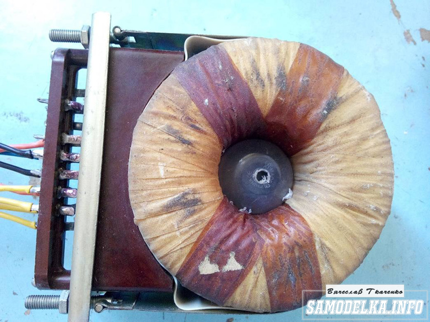
I will start the assembly with at the same time I will describe it. The heart of the power supply (and the entire amplifier, probably) will be the TST-143 toroidal transformer, which I at one time (4 years ago) tore with meat from some kind of tube generator right at the time it was being taken to a landfill. Unfortunately, I didn’t manage to do anything more. L, it’s a pity for such a generator, or maybe it was also a worker or it was possible to fix it ... Okay, I digress. Here he is my enforcer.


Of course, I found a diagram for it on the Internet.

The rectifier will be on a diode bridge with a filter on the inductor for anode power. And 12 volts to power the backlight and anode voltage. Throttle I have.

Its inductance was 5 henries (according to the device), which is quite enough for good filtering. And the diode bridge was found like this.

Its name is BR1010. (10 amps 1000 volts). I'm starting to cut out the amplifier. I think it will be something like this.
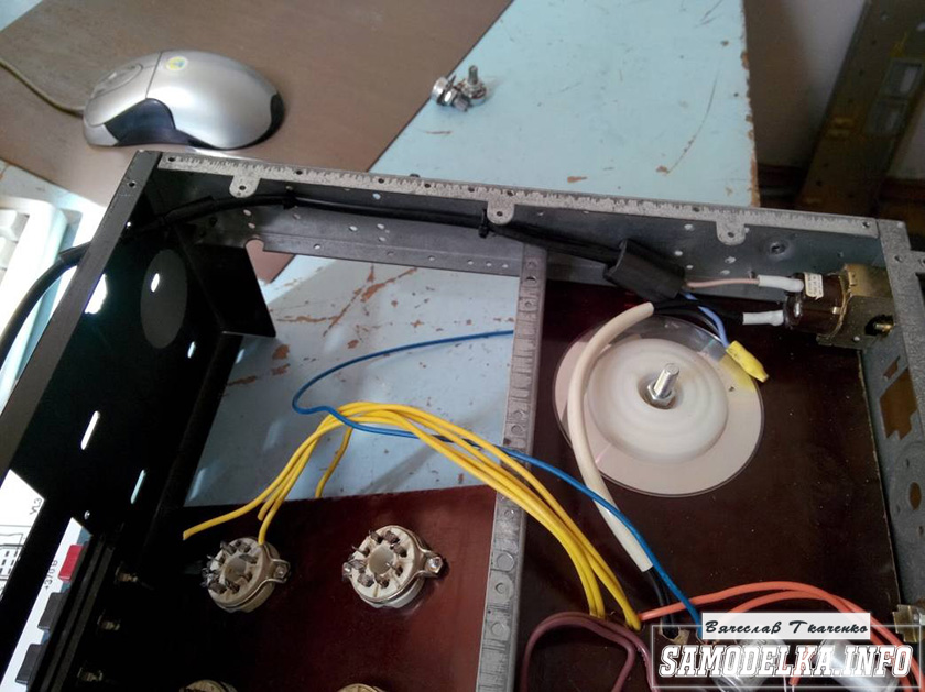
I mark and cut holes in the textolite for panels for light bulbs.
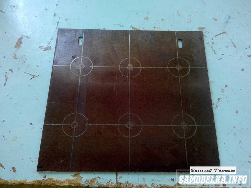


It turns out not bad :) so far I like everything.

And so, and so. drilling sawing :)
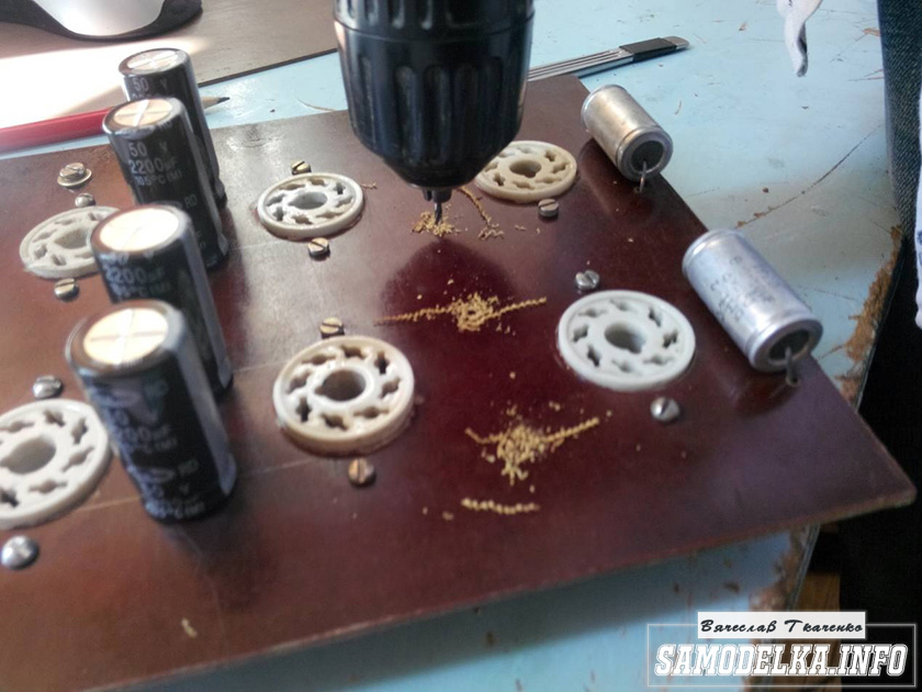
Something began to emerge.
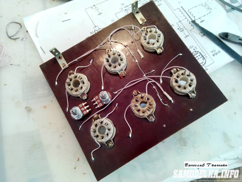
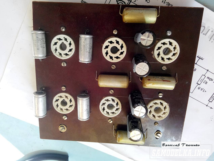
I found a fluoroplastic wire in old stocks and immediately all the alternatives and compromises regarding the wire for installation disappeared without a trace :).


This is how the installation turned out. Everything is as if “kosher” the incandescences are intertwined, the earth is at one, practically, point. Should work.

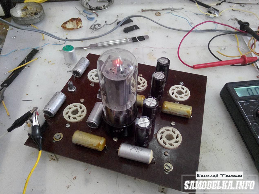
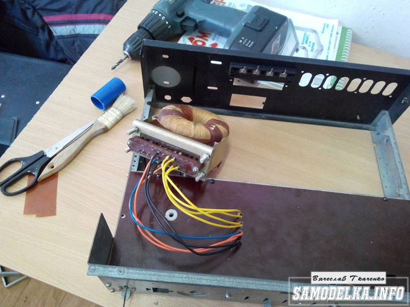
It's time to fence food. After checking and checking all the output windings of the trance, I soldered all the necessary wires to it, and began to install it according to the accepted plan.

As you know, in our not easy anywhere without materials at hand: the container from the Kinder Surprise came in handy.
And a Nescafe lid and an old CD


I ripped out TV and monitor boards. All capacities are at least 400 volts (I know that I need more, but I don’t want to buy).
I shunt the bridge with containers (which ones were at hand, I’ll probably change them later)
It turns out a bit too much, but oh well, it will sag under load :)
I use the regular power switch from the amplifier (clear and soft).

Done with this. Well done :)
Illumination for the body of the tube amplifier.
To implement the backlight, an LED strip was purchased.

And installed as follows in the case.
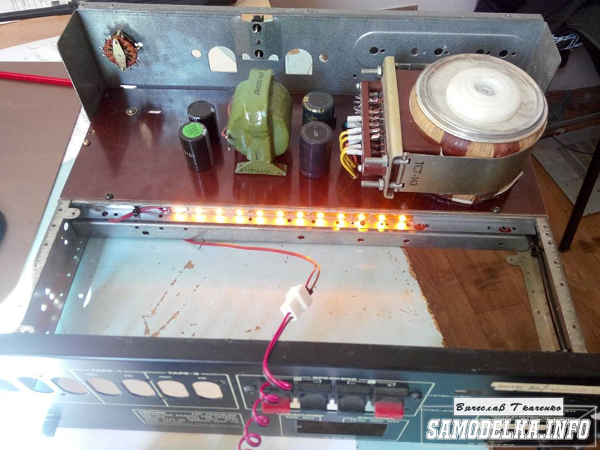

Now the glow of the amplifier will be visible in the daytime. To power the backlight, I will make a separate rectifier with a stabilizer on some kind of KRKEN-like microcircuit (which I can find in the trash), from which I plan to power the anode voltage supply delay circuit.
Delay relay.
Digging through the bins of my homeland, I found just such a completely untouched thing.

This is a radio time relay kit for a photo enlarger.

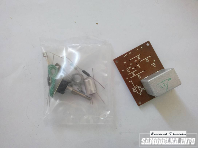
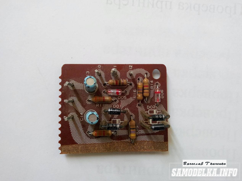
We collect, we check, we try on.

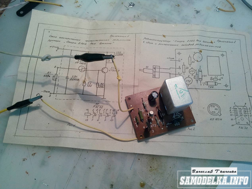

The response time was set to about 40 seconds, and the variable resistor was replaced by a constant one. The case is coming to an end. It remains to put everything together, put the muzzle, indicators and regulators.
Regulators (input variables)
They say that the sound quality can greatly depend on them. In short, I put these

Dual 100 kOhm. since I have two of them, I decided to parallelize the conclusions, thereby obtaining 50 kOhm and increased resistance to wheezing :)
Indicators.
I used standard indicators, with standard illumination

The connection diagram was mercilessly bitten by me from the native board and is also involved.
Here's what I ended up with.
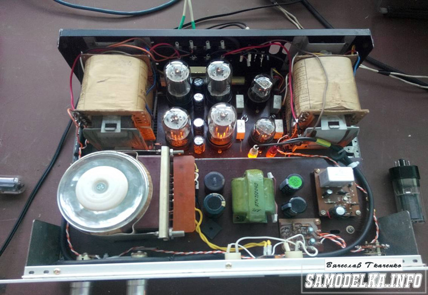


When checking the power, the amplifier showed a voltage at the output of 10 volts of an undistorted sinusoid with a frequency of 1000 Hz to a load of 4 ohms (25 watts) equally across the channels, which pleased :)
When listening, the sound was crystal clear without background and dust, as they say, but too monitor, or what? nice but flat.
I naively thought that he would play without timbres, but ...
When using the software equalizer, we managed to get a very beautiful sound that everyone liked. Thank you all very much!!!
Raised the budget audio system to a new level. About the PAS-240 amplifier, the 4th model from Audio Profile.
My system:
1. CD player Marants 6002 - budget.
2. Markana DAC is a masterpiece of audio technology.
3. Amplifier Marants 7001-budget.
4. Acoustics Dali Ikon-2 - budget.
5. Seeing off Pavlov and Markitanov - no complaints, super. Output from SD to DAC optics - no complaints.
I started to cost my system based on the budget, first without a DAC. Changed speakers, changed to expensive wires. Everything is not right. Rummaged through the literature, talked with specialists and came to the conclusion that, in order to move to the audiophile level, you first need a DAC. Everything was born in pain and the DAC Markana was born. I put it down and almost cried, it would seem, that's what we need. Enjoy the sound, clear stereo scene, great detail. The upper frequencies at first pleased with their sonority, but then they began to annoy. There weren’t enough lows, I bought a Real Quake subwoofer - no complaints, excellent, the middle began to be missed. It is clear that it was necessary to change both the acoustics and the amplifier. But due to the lack of availability, I decided to start with the amplifier.
Based on my experience, and not only, I decided to choose from Russian manufacturers, since, all other things being equal, they are 2 or even 5 times cheaper than bourgeois ones. I also listened to more expensive than my models Starodubtsev, Alex, Musatov. Yes, the amplifiers are good, but not so much that there was a serious jump in sound. After some time, I found information about the "PAS-240" Model 4 from "Audio Profile", read the characteristics, contacted and, after a long correspondence, took the 4th model home from the Moscow representative for testing.
They brought it home with their son, staged it, and started with the opera "Village Honor" with Placido Damingo performed by a symphony orchestra, then jazz, then good old rock, and then everything in a row. They sat amazed. Deep, resilient low frequencies appeared, even in a heavy car, where drum roll was torn like a machine gun, everything was detailed and clear, annoying high frequencies were gone, the middle was simply amazing. The main thing was meat, which was so lacking in Marants and in general in SDyuki. Expanded stereo scene. We got real pleasure, it became clear that we found what we were looking for.
But the main indicator is my wife. When I turned on Marants, she ran away from the room. Now she was happy to sit with us for 4 hours and listen, although she is not a fan of this business by definition. Her phrase speaks volumes: "the sound has become noble." In general, they offered to buy! At the first listening, and my son (he is a fanatic music lover) for two days, from morning to evening, listened and did not get out of us.
Even on my "simple" acoustics Dali Ikon (Dali Ikon) 2, the sound of "PAS-240" is strikingly different from Marants! Now you do not need a subwoofer, the bottoms are enough. By the way, I have a good sub Rel Quake, maybe someone needs it?
Every day I like the sound more and more. Recommend! The PAS-240 Model 4 is the ultimate high-end amplifier. Take Russian, do not feed the bourgeois!
Addition:
I replaced the Dali Ikon 2 acoustics as the weakest link in my system. This is ALEKS acoustics with its super tweeters. With your mustache, it sounds great. There is everything and exactly at all frequencies. Alex himself listened to me at home and appreciated.
Listened to ProAki for 170 tr. - everything is smooth, good, but not High End. Weak detailing, the depth of the scene is not heard. I settled on ALEKS. There is everything! And most importantly, the sound is close to natural.
They compared your VCL head-on (Model 4 "PAS-240" for 85 tr) with Briston for 300 thousand rubles. On floor acoustics MTUSI "TOPAZ" with super tweeters. Result: Yours is at least as good! Was satisfied.
Already bought ALEKS and his tweeters. The price of acoustics is 80 thousand + 15 thousand for ST-9 super tweeters. Total 95 thousand. Satisfied as a mammoth. There are no disadvantages. The sound is honest, close to natural without embellishment. But, you need - high quality recordings. Otherwise, all the dirt and flaws are audible. With such acoustics and a mustache, listening to bad records is no wind. He, Alex, positions them as High Grand High. With such acoustics, I set the volume to 7, a maximum of 10 hours. Loud. But even at low volume, the detail is gorgeous.
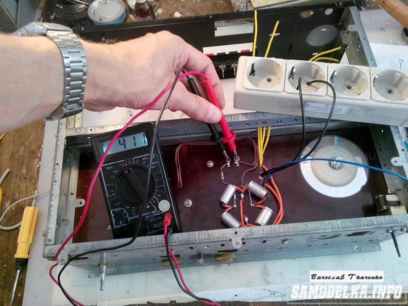
REVIEW 41. MODEL 4 (ROMAN, KRASNOYARSK)
Yesterday I was notified that the cargo had arrived, today I picked up the unit early in the morning. When they rolled out the package to me, I was already freaked out by its size, where I put it, even though I have a station wagon :) True, they reassured me that this is just a protective crate and we will not give it to you. The seals were opened in front of me, I took the contents and was gone.

First impressions. I liked the appearance, it looks pretty solid, one iron and no plastic - class!, And the family didn’t say anything about this, so everything is buzzing. The inscriptions, twists, legs are made perfectly (I especially liked the legs), they look solid. Power button - class!
In general, the sound is clear, which I already like, the rise of the bottoms when listening at low volume (which often happens) adds meat to the sound, which I have been deprived of for a long time and this, of course, pleases! I have not yet owned a device in such a price niche. In recent years, I listened to music on the ONKYO TX-NR 708 receiver, floor acoustics JBL ES 90.
The sound of the amplifier after the receiver, which is understandable in general, I liked it. Excellent sound dynamics, good detail, resolution, the sound stage does not protrude forward, everything is in order in terms of depth and width of the sound stage. On good CD recordings, I heard a lot of new things in familiar recordings that I had not heard before, for example, on the Iron Maiden album “Somewhere in Time”, so much appeared that I was not much discouraged. Haven't figured out if this is good or bad yet.
There is more than enough power for the house, I don’t turn the regulator for more than 9.5 hours, it sings so mom don’t cry, the subwoofer is not needed yet. Putting him in the bedroom because of this, as planned, will not work. Even at a low volume, everything is enough, you can not even turn on loudness, loudness raises the bottoms, well, very cool, I did not expect this. I wanted to hear from the bottom, what I once heard on my Pioneer A-702R, it turned out even better. In general, I did not notice the coloring of the sound (loudness does not count), everything is quite neutral. If the music is energetic, then it plays very energetically, if it is calm, then the sound is the same. The nature of the sound depends on the phonogram, how it is recorded and how it sounds. Under AC / DC, you involuntarily want to stomp your foot and it seems that everything around is bouncing to the beat of the music.
- most connoisseurs of quality music, who know how to handle soldering equipment and have some experience in repairing radio equipment, can try to assemble a high-end tube amplifier, which is usually called Hi-End, on their own. Tube devices of this type belong in all respects to a special class of household radio-electronic equipment. Basically, they have an attractive design, while nothing is covered by a casing - everything is in sight.
After all, it is clear that the more you can see the electronic components installed on the chassis, the more authority the device has. Naturally, the parametric values of the tube amplifier are significantly superior to models made on integral or transistor elements. In addition to this, when analyzing the sound of a tube device, all attention is given to a personal assessment of the sound, rather than the image on the oscilloscope screen. In addition, it differs in a small set of used parts.
How to choose a tube amplifier circuit
In the case of choosing a pre-amplifier circuit, there are no particular problems, then when choosing a suitable final stage circuit, difficulties may arise. Tube Audio Power Amplifier may have several options. For example, there are single-stroke and push-pull devices, and also have different modes of operation of the output path, in particular "A" or "AB". The output stage of the single-ended amplification is by and large a model, because it is in the "A" mode.
This mode of operation is characterized by the lowest values of non-linear distortion, but its efficiency is not high. Also, the output power of such a cascade is not very large. Therefore, if it is necessary to sound an internal space of medium size, a push-pull amplifier with an “AB” operating mode will be required. But when a single-cycle device can be made with only two stages, one of which is preliminary and the other is amplifying, then a driver is needed for a push-pull circuit and its correct operation.
But if single tube audio power amplifier may consist of only two stages - a preamplifier and a power amplifier, then a push-pull circuit for normal operation requires a driver or a stage that generates two voltages of identical amplitude, shifted in phase by 180. The output stages, regardless of whether it is single-ended or push-pull, assume the presence in the circuit output transformer. Which acts as a matching device for the interelectrode resistance of a radio tube with low acoustic resistance.
True fans of "tube" sound argue that the amplifier circuit should not have any semiconductor devices. Therefore, the power supply rectifier must be implemented on a vacuum diode, which is specially designed for high-voltage rectifiers. If you intend to repeat a working, proven tube amplifier circuit, then you do not need to immediately assemble a difficult push-pull device. To sound a small room and get the perfect sound picture, a single-ended tube amplifier is fully enough. In addition, it is easier to manufacture and configure.
The principle of assembly of tube amplifiers
There are certain rules for the installation of radio-electronic structures, in our case it is tube audio power amplifier. Therefore, before starting the manufacture of the device, it would be desirable to thoroughly study the paramount principles for assembling such systems. The main rule when assembling structures on vacuum radio tubes is the wiring of connecting conductors along the shortest possible path. The most effective method is to refrain from using wires in places where you can do without them. Fixed resistors and capacitors must be installed directly on the lamp sockets. At the same time, special “petals” should be used as auxiliary points. This method of assembling a radio-electronic device is called "hinged mounting".
In practice, when creating tube amplifiers, printed circuit boards are not used. Also, one of the rules says - avoid laying conductors parallel to each other. However, such, at first glance, chaotic wiring is considered the norm and is fully justified. In many cases, when the amplifier is already assembled, a low-frequency background is heard in the speakers, it must be removed. The primary task is the correct choice of the "ground" point. There are two ways to organize grounding:
- The connection of all wires going to the "ground" at one point - called "asterisk"
- Installing an energy-efficient electrical copper bus around the perimeter of the board, and solder the conductors to it.
It is necessary to verify the place for the ground point by experiment, listening for the presence of a background. To determine where the low-frequency background comes from, you need to do this: You need to use the method of sequential experiment, starting with the double triode of the preamplifier, to short the lamp grids to ground. In the case of a noticeable decrease in the background, it will become clear which circuit of which lamp is “phoning”. And then, also empirically, you need to try to eliminate this problem. There are auxiliary methods that are mandatory for use:
Pre stage lamps
- Vacuum lamps of the preliminary stage must be closed with caps, and they, in turn, must be grounded
- Cases of trimmer resistors are also subject to grounding
- Lamp wires need to be twisted
Tube Audio Power Amplifier, or rather, the filament circuit of the pre-amplifier lamp can be powered with direct current. But in this case, you will have to add another rectifier assembled on diodes to the power supply. And the use of rectifier diodes in itself is undesirable, as it breaks the constructive principle of manufacturing a tube Hi-End amplifier without the use of semiconductors.
The pair placement of the output and mains transformers in a lamp device is quite an important point. These components must be installed strictly vertically, thereby reducing the background level from the network. One of the effective ways to install transformers is to enclose them in a housing made of metal and grounded. The magnetic circuits of transformers must also be grounded.
retro components
Radio tubes are devices from distant times, but again come into fashion. Therefore, it is necessary to complete tube audio power amplifier the same retro elements that were installed in the original lamp designs. If it concerns fixed resistors, then carbon resistors with high parameter stability or wire ones can be used. However, these elements have a large spread - up to 10%. Therefore, for a tube amplifier, the best choice would be to use small-sized precision resistors with a metal-dielectric conductive layer - C2-14 or C2-29. But the price of such elements is significantly high, then MLTs are quite suitable for them.
Particularly zealous adherents of the retro style get the "audiophile's dream" for their projects. These are BC carbon resistors, developed in the Soviet Union specifically for use in tube amplifiers.  If desired, they can be found in tube radios of the 50-60s. If, according to the scheme, the resistor should have a power of more than 5 W, then PEV wire resistors coated with vitreous heat-resistant enamel are suitable.
Capacitors used in tube amplifiers are basically not critical to one or another dielectric, as well as to the element design itself. Any type of capacitor can be used in the tone control paths. Also in the rectifier circuits of the power supply, you can install any type of capacitors as a filter. When designing high-quality low-frequency amplifiers, isolation capacitors installed in the circuit are of great importance.
It is they who have a special influence on the reproduction of a natural, not distorted sound signal. Actually thanks to them we get an exceptional "tube sound". When choosing isolation capacitors to be installed in tube audio power amplifier, special care must be taken to keep the leakage current as low as possible. Because the correct operation of the lamp, in particular its operating point, directly depends on this parameter.
In addition, we must not forget that the decoupling capacitor is connected to the anode circuit of the lamp, which means that it is under high voltage. So, such capacitors must have an operating voltage of at least 400v. One of the best capacitors working as a transition capacitor are JENSEN capacitors. It is these capacitances that are used in top-end HI-END class amplifiers. But their price is very high, reaching up to 7500 rubles for one capacitor. If you use domestic components, then the most suitable would be, for example: K73-16 or K40U-9, however, they are significantly inferior in quality to branded ones.
Single Ended Tube Audio Power Amplifier
The presented tube amplifier circuit has three separate modules:
- Pre-amplifier with tone control
- The output stage, that is, the power amplifier itself
- Source of power
The preamplifier is made according to a simple scheme with the ability to adjust the signal gain. It also has a pair of separate bass and treble tone controls. To increase the efficiency of the device, an equalizer for several bands can be introduced into the design of the pre-amplifier.
Preamp Electronics
The preamplifier circuit presented here is made on one half of a 6N3P double triode. Structurally, the preamplifier can be made on a common frame with an output stage. In the case of the stereo version, then naturally two identical channels are formed, therefore, the triode will be fully involved. Practice shows that when starting to create any design, it is best to first use the circuit board. And after adjusting, already assemble in the main body. Provided that the preamplifier is assembled correctly, it starts to work synchronously with the supply voltage without any problems. However, at the setup stage, you need to set the voltage of the anode of the radio tube.
The capacitor in the output circuit C7 can be used K73-16 with a rated voltage of 400v, but preferably from JENSEN, which will provide the best sound quality. Tube Audio Power Amplifier not particularly critical to electrolytic capacitors, so any type can be used, but with a voltage margin. At the stage of tuning work, we connect a low-frequency generator to the input circuit of the pre-amplifier and apply a signal. An oscilloscope must be connected to the output.
Initially, the input signal range is set within 10 mv. Then we determine the value of the voltage at the output and calculate the amplifying factor. With an audio signal in the range of 20 Hz - 20000 Hz at the input, you can calculate the bandwidth of the amplifying path and depict its frequency response. By selecting the capacitive value of the capacitors, it is possible to determine an acceptable proportion of high and low frequencies.
Setting up a tube amp
Tube Audio Power Amplifier implemented on two octal tubes. In the input circuit, a double triode with separate 6N9S cathodes is installed, connected in parallel, and the final stage is made on a rather powerful output beam tetrode 6P13S, connected as a triode. Actually, it is the triode installed in the final path that creates the exceptional sound quality.
To perform a simple adjustment of the amplifier, an ordinary multimeter will suffice, and in order to perform accurate and correct adjustment, you must have an oscilloscope and an audio frequency generator. You need to start by setting the voltage on the cathodes of the 6H9C double triode, which should be within 1.3v - 1.5v. This voltage is set by selecting a constant resistor R3. The current at the output of the beam tetrode 6P13S should be in the range from 60 to 65 mA. If a powerful constant resistor 500 Ohm - 4 W (R8) is not available, then it can be assembled from a pair of two-watt MLTs with a nominal value of 1 kOhm and connected in parallel. All other resistors indicated in the diagram can be installed of any type, but preference is still C2-14 is given.
Just like in the preamplifier, an important component is the decoupling capacitor C3. As mentioned above, the ideal option would be to install this element from JENSEN. Again, if there are none at hand, then Soviet film capacitors K73-16 or K40U-9 can also be used, although they are worse than overseas ones. For the correct operation of the circuit, these components are selected with the lowest leakage current. If it is impossible to perform such a selection, it is still advisable to buy elements from foreign manufacturers.
Amplifier power supply
The power supply is assembled using a 5Ts3S direct-heated kenotron, which provides AC rectification that fully complies with the design standards for HI-END class tube power amplifiers. If it is not possible to purchase such a kenotron, then two rectifier diodes can be installed instead.
The power supply unit installed in the amplifier does not require any adjustment - it turned on and that's it. The topology of the circuit makes it possible to use any chokes with an inductance of at least 5 Gn. As an option: the use of such devices from outdated TVs. The power transformer can also be borrowed from old Soviet-made lamp equipment. If you have the skills, you can make it yourself. The transformer must consist of two windings with a voltage of 6.3v each, providing power to the radio tubes of the amplifier. Another winding should be with an operating voltage of 5v, which are fed into the kenotron filament circuit and the secondary one, which has a midpoint. This winding guarantees two voltages of 300v and a current of 200mA.
Power amplifier assembly sequence
The assembly procedure for a tube sound amplifier is as follows: first, a power source and the power amplifier itself are made. After the settings are made and the necessary parameters are set, the preamplifier is connected. All parametric measurements with measuring instruments should be done not on a “live” acoustic system, but on its equivalent. This is in order to avoid the possibility of removing expensive acoustics from standing. The equivalent load can be made from powerful resistors or from thick nichrome wire.
Next, you need to deal with the case for the tube sound amplifier. The design can be developed independently, or borrowed from someone. The most affordable material for the manufacture of the case is plywood. Lamps for the output and preliminary stages and transformers are installed on the upper part of the housing. On the front panel there are devices for adjusting the timbre, sound and an indicator for supplying voltage. In the end, you may end up with devices like the models shown here.
An article about the creation of an amplifier, in the circuitry and design of which non-traditional technical solutions are used. The project is non-commercial.
I started getting interested in audio equipment and listening to music a very long time ago, since the late 80s and for a long time I was firmly convinced that any UM with the label Sony, Technics, Revox, etc. much better than domestic amplifiers, and homemade ones - even more so, since Western brands have both technology, and the highest quality parts, and experience.
Everything changed after the article by A.M. Likhnitsky in the magazine Audiomagazin No. 4 (9) 1996, which described the development and introduction into production in the 70s of the Brig-001 amplifier, of which he is the author. By chance, after a short period of time, the faulty Brig-001 from the first issues fell into my hands. Using only original domestic parts of the 70s - 80s, I brought this PA to its original state so that its sound abilities could be assessed as reliably as possible.
Connecting the Brig-001 amplifier instead of the Technics SU-A700 home audio system shocked me - Brig sounded much better, although the parameters were more modest and were 20 years older. which was done in 1998, mainly on the domestic element base of military acceptance. The new device did not leave any chances on comparative auditions to already more eminent amplifiers, such as NAD and Rotel middle models of the line, and was quite convincing even in comparison with their older counterparts. The project was further developed in 2000, in the form of a two-block PA according to the same scheme, but with a new design and increased power consumption of the power supply. It has already been compared with transistor and tube amplifiers from the price range up to several thousand US dollars, and in many cases it surpassed them in sound quality. Then I realized one more thing - the design of the amplifier decides almost everything.
Analyzing the results of listening, especially with the participation of those amplifiers that sounded better than my two-block PA, I came to the conclusion that either good tube designs or transistor ones without general feedback were more often at their best. Among them were PAs with deep LLCOS, the specifications of which often showed off very high slew rates of the output voltage - 200 V / μs and higher. As a rule, these devices were expensive, and their circuitry was not publicly available. My tip also had a fairly deep LLC, but low speed compared to them - about 50 V / μs, with a comparable output voltage. He sometimes lacked the ability to fully convey the naturalness of the timbres of musical instruments and the voices of the performers, the emotions of the musicians. On some compositions, the presentation of music was simplified, part of the timbre richness was hidden behind a kind of thin gray veil. This is probably what is called the "transistor sound" inherent in the PA with feedback.
The reasons for the "transistor" sound in the PA with LLC have been repeatedly discussed both in forums, and in books on circuitry, and in publications of magazines corresponding to this topic. One of the known theories, which I also adhere to, is that the low output impedance of amplifiers covered by common feedback, measured on a sinusoidal signal and active load, does not remain so at all when playing music on speakers, which allows back-EMF signals from dynamic heads penetrate from the output of the amplifier through the feedback circuits to its input. These signals are not subtracted by OOOS, since they already differ in shape and have a phase shift relative to the original ones, so they are safely amplified and again enter the speakers, causing additional distortion and extraneous sounds in the audio path. Methods to combat this effect are periodically discussed. As examples, the following can be given:
1. "False" channel of LLC, when its signal is taken from one of the parallel-connected elements of the final stage, which is not connected to the AC, but is loaded on a resistor of a certain rating.
2. Reducing the output impedance of the PA even before the coverage of the LLC.
3. Increasing the speed inside the LLCOS loop up to "cosmic" speeds.
Naturally, the most effective way to deal with LLCOS artifacts is to exclude it from the PA circuitry, but my attempts to build something worthwhile without LLCOS on transistors were unsuccessful. Starting from scratch in the field of tube audio technology was considered inappropriate for myself. The method from point "1" raised a lot of questions, so I began experiments with increasing performance inside the feedback loop, taking into account point "2". I would like to immediately draw attention to the fact that the slew rate of the output voltage, sufficient for the correct reproduction of the attack of the sound of musical instruments by the amplifier, is a relatively small value, and its ultra-high values are relevant only in relation to the operation of the LLC.
It is clear that in amplifiers with a common feedback loop, not all problems are solved by increasing the slew rate, but the main idea was the following, all other things being equal: the higher the speed inside the feedback loop, the faster the “tails” of signals that are not compensated by feedback will decay and what should be some threshold of their visibility by ear, taking into account the reduction in the duration of artifacts with an increase in performance. Moving in this direction, I very quickly ran into the problem of approaching at least the bar of 100 V / μs in the PA on discrete elements - if there were cascades on powerful transistors in the circuit, everything turned out to be much more difficult. In amplifiers with voltage feedback, high speed did not “match” with stability, and in PA with TOC (with current feedback) it was not possible, without using an integrator, to get an acceptable level of constant voltage at the output, although everything was fine with speed in order, and with the stability of the problem was solved. The integrator does not change the sound for the better, in my opinion, so I really wanted to do without it.
The situation was almost a dead end, and not for the first time there were thoughts that if you create a power amplifier with voltage feedback, then using the topology of a preliminary or telephone amplifier, it will be much easier to make it high-speed, broadband, stable and without an integrator, which, in my opinion, should have a positive effect on the sound quality. It only remained to figure out how to implement it. There was no solution for almost 10 years, but during this time a home “R&D” was carried out to study the effect of the output voltage slew rate inside the general feedback loop on the sound quality, for which a mock-up was created that allows testing various composite amplifiers on an op-amp.
The results of my "R&D" were as follows:
1. The speed and bandwidth of a composite amplifier must increase from input to output.
2. The correction is only unipolar. No capacitors in OOS circuits.
3. For an amplifier with a maximum output voltage of 8.5 V RMS, with an OOS depth of about 60 dB, a noticeable increase in sound quality appears somewhere in the range of 40-50 V / μs, and then closer to 200 V / μs, when the amplifier practically ceases to be "heard" LLC.
4. Above 200 V / µs, no noticeable improvement was observed, but for a PA with an output voltage of 20 V RMS, for example, 500 V / µs is already needed to achieve the same result.
5. The input and output filters that limit the PA band do not perform in the best way in sound, even if the cutoff frequency is significantly higher than the upper limit of the audio range.
After unsuccessful experiments with PA on discrete elements, my eyes turned to high-speed op amps and integrated buffers that have the highest output current. The search results were disappointing - all devices with a large output current are hopelessly "slow", and high-speed ones have a low allowable supply voltage and not a very large output current.
In 2008, by chance, an addition to the specification for the BUF634T integrated buffer was found on the Internet, where the developers themselves provided a composite amplifier circuit with three such buffers at the output connected in parallel (Fig. 1) - it was then that the idea came up to design a PA with a large number of such buffers in the output stage.
The BUF634T is a wideband (up to 180 MHz), ultra-fast (2000 V/µs) parallel follower buffer with 250 mA output current and up to 20 mA quiescent current. Its only drawback, one might say, is the low supply voltage (+\- 15 V nominal and +\- 18 V - the maximum allowable), which imposes certain restrictions on the amplitude of the output voltage.
I finally chose the BUF634T, resigned to the low output voltage, since all the other characteristics of the buffer and its sound properties completely suited me, and began to design the PA with a maximum output power of 20 W / 4 Ohm.
Fig.1
The choice of the number of elements of the output stage was reduced to obtaining an PA operating in a pure class A for a load of 8 ohms and to ensure the modes of the elements of the output stage in terms of current far from the limit. The required quantity was determined as 40+1. For the additional 41st buffer, the minimum quiescent current was set - only 1.5 mA, and it was supposed to be used in order to carry out the first launch of the structure even before installing the radiators, as well as to carry out some settings and experiments in more comfortable conditions. It later turned out to be a very good idea.
As is known, the parallel connection of integrated circuits does not lead to an increase in the overall noise level and Kr, but the input resistance of such a module decreases and its input capacitance increases. The first is not critical: the input impedance of the BUF634T is 8 MΩ and, accordingly, the total will not be lower than 195 kΩ, which is more than acceptable. With the input capacitance, the situation is not so rosy: 8 pF per buffer gives 328 pF of total input capacitance, which is already a noticeable value and will negatively affect the operation of the swinging op-amp (Fig. 1). To globally reduce the output impedance of the final stage driver, another op amp was introduced in front of it, covered by its own OOS loop. Thus, the circuit grew into a triple composite amplifier, but in which all the points of the results of my "R&D" were carried out. After numerous experiments, the composition of the CL of the composite amplifier was determined: AD843 took the place of the input op-amp, and the powerful high-speed op-amp AD811, with current feedback, was designed to act as the output buffer of the driver stage. To ensure that the required speed of the PA (above 200 V/µs) was obtained, the AD811 gain was chosen equal to two, which ideally doubled the AD843’s 250 V/µs and allowed us to hope that, with appropriate circuitry and a successful design, it would be possible to maintain the required value of the output slew rate. voltage for the complete PA circuit. Looking ahead, I note that the expectations were justified - the real value of this parameter with output buffers turned out to be more than 250 V / μs.
The general scheme of the amplifier has undergone many changes during the tuning and debugging, so I will immediately give the final version, which includes all the corrections and improvements (Fig. 2).
 Rice. 2
 The structure is simple - an input selector, a volume control, a UN, a buffer amplifier for recording to a tape recorder, an end stage and a protection relay, which is controlled by an optoelectronic circuit for delaying the connection of speakers and protecting them from DC voltage (Fig. 3). For compactness, buffers and their associated resistors are combined in 10 pcs, but the part numbering is kept in full. As seen in fig. 2, the contact group of the UM protection relay (K6) is not included in the sound transmission circuit and closes the output to ground during transients or possible emergencies.
 Rice. 3
 For BUF634T, such an inclusion is not dangerous, especially since all buffers have a 10 Ohm resistor at the output. In order to avoid loss of stability by the amplifier, due to a ground fault of the OOOC resistor (R15), simultaneously with the operation of the K6 relay, the K5 relay is also closed, forming a temporary circuit of the OOOC driver stage through the resistor R14. If the values of the resistors R14 and R15 are equal, then there are no extraneous clicks in the speakers during the operation of the protection, even if they are more than 100 dB sensitive.
It is worth noting that the first year of operation, the amplifier functioned reliably without the K5 relay, and without the temporary OOS circuit with R14, but I was haunted by the very possibility of self-excitation during the operation of the protection, so these additional elements were introduced. By the way, the amplifier works fine even without covering the final stage with an LLC circuit. You can remove the resistor R15, the relay K5, and use the resistor R14 to close the feedback in the UN, which I did, as an experiment. I liked the sound less this way - it is possible that this is the option when we get more pluses than minuses from using ultra-fast feedback.
The diagram also shows that one of the 4 inputs (CD input) puts the PA into the DC amplifier (UCA) mode, and the Tape Monitor function is implemented from the LP input (vinyl disc player), and without additional contact groups in the circuit signal passing. I am a fan of analog recording, so I did just that for myself. If there are no analog sound recording devices in the audio system, then the block on the op-amp IC1 can be omitted.
The diagram does not show blocking capacitors for power - for convenience, they will be displayed on the power supply diagram.
The ideology of this amplifier is largely different from the classical one and is based on the principle of current sharing - each element of the final stage operates with a small current, in a very comfortable mode, but a sufficient number of these elements, connected in parallel, can provide this 20-watt amplifier with maximum current in the load more than 10 A constantly and up to 16 A in an impulse. Thus, the output stages are loaded during listening, on average, by no more than 5-7%. The only place in the amplifier where high currents can flow is the two copper bars on the PA board leading to the speaker terminals where the outputs of all the BUF634Ts of each channel come together.
Within the framework of the same ideology, the PA power supply was also developed (Fig. 4) - in it all power elements also work with relatively small currents, but there are also many of them, and as a result, the total power of the PSU is 4 times higher than the maximum consumed by the amplifier. The PSU is one of the most important parts in an amplifier that I think is worth looking at in more detail. The amplifier is built using the “double mono” technology and therefore contains on board two independent power supplies for signal circuits, fully stabilized, with a power of 150 W each, separate stabilizers for the voltage amplifier, as well as a power supply for providing service functions, powered by a separate mains transformer 20 W. All BP network transformers are phased with each other - in the manufacture of transformers, the conductors of the beginning and end of the primary windings were marked.
 Rice. 4
 The power part of each channel is divided into 4 bipolar lines, which made it possible to reduce the load current of each stabilizer to a value of only 200 mA, and increase the voltage drop across them to 10 V. chains. It was possible to use more "advanced" LT317 and LT337 microcircuits, but there were many original LM7815C and LM7915C from Texas Instruments, with an output of 1.5 A, which determined the choice. In total, the signal circuits of the amplifier are powered by twenty such integral stabilizers - 4 for the UN and 16 for the VC (Fig. 4). Each pair of power unit stabilizers feeds 10 pcs. BUF634T. One pair of UN stabilizers is loaded with a bundle of AD843+AD811 of one channel. The RC circuit (R51, C137, for example) in front of the UN stabilizers has a dual purpose: it protects the rectifier from inrush current when the PA is powered on and forms a filter with a cutoff frequency below the edge of the audio range (about 18 Hz), which significantly reduces the amplitude of the rectified voltage ripple and the level of other interference, which is important for the input stages.
Another feature of the power supply is that the main part of all filter capacitors (160,000 microfarads out of 220,000 microfarads) are located after the stabilizers, which makes it possible to deliver a large current to the load, if necessary. However, this required the introduction of a Soft Start system to protect the stabilizers when the amplifier was turned on and the battery was initially charged. As seen in fig. 4, Soft Start is implemented quite simply, on one transistor (VT1), which with a delay (about 9 s) connects the low-current relay K10, which, in turn, includes 4 high-current relays K11-K14, with four groups of contacts in each, closing 16 current limiting resistors with a nominal value of 10 ohms (R20, R21, for example). That is, when the amplifier is turned on, the maximum peak current of each stabilizer is strictly limited to 1.5 A, which is its normal operating mode. I don’t use “Soft Start” in the primary circuit of 220 V - in the event of a break in the current-limiting resistor or loss of contact at the soldering points of its conclusions, serious consequences for the entire UM are possible.
The PSU for service functions is responsible for connecting the mains voltage to the main transformers (relay K8), powering the components of the Soft Start system, the input selector relay, the supply voltage of which, by the way, is also stabilized. A +5 V output is also implemented, routed to the connector on the rear panel of the PA - this is already a kind of standard in my amplifiers for simultaneously turning on any external units. This amplifier may well work as an amplifying-switching device (pre-amplifier) for more powerful monoblocks, for example, which will turn on when a control voltage of +5 V is applied to them.
The power supply of the amplifier was built in the first place, since further development of the development process required the presence of a full-fledged power supply unit, so that the first launch, experiments and tuning should be carried out in a mode close to real operating conditions. After the successful launch of all power circuits, an input selector, a turn-on delay and speaker protection unit, as well as a composite amplifier with one BUF634T (BUF41) at the output, were assembled on the PA board as a final stage. As mentioned above, this 41st buffer has a low quiescent current and does not require installation on a radiator, but headphones were now easily connected to the output of the amplifier, which made it possible to control auditory, along with measurements. At the end of debugging the circuit with one output buffer in each channel, it remained only to solder the remaining 80 pcs. and see what comes of it. I didn’t have any guarantees of a positive result, and it couldn’t be - there was no information about successfully implemented similar projects by other developers. As far as I know, there are no designs based on parallel op amps with similar speed either in Russia or abroad even now.
The result, however, was positive. Since the amplifier was assembled on a rigid chassis made of aluminum bars, where all the switching connectors were fixed (photo 1), it was possible to connect it to the audio system without a case. The first auditions have begun, but more on that later - first, I will give some parameters:
 Photo 1
 Output Power: 20W/4Ω, 10W/8Ω (Class A)
Bandwidth: 0 Hz - 5 MHz (CD input)
1.25Hz - 5MHz (AUX, Tape, LP inputs)
Output voltage slew rate: more than 250V/μs
Gain: 26 dB
Output impedance: 0.004 ohm
Input impedance: 47 kOhm
Input sensitivity: 500 mV
Signal to noise ratio: 113.4 dB
Power Consumption: 75W
Power supply power: 320W
Overall dimensions, mm: 450x132x390 (excluding the height of the legs)
Weight: 18 kg
Based on the parameters, without even looking at the circuit, it is obvious that the amplifier does not have input and output filters, as well as external frequency correction circuits. But it is worth noting that at the same time it is stable and works fine even with unshielded interconnect cables. Quite informative in this regard is the oscillogram of a meander of 2 kHz 5V / div, at a load of 8 ohms at an almost maximum output voltage level (Photo 2).
 Photo 2
 From my point of view, this is the merit of the correct wiring of the "earth" conductors, as well as their large cross-sectional area: from 4 sq. mm. up to 10 sq. mm. (including PCB tracks).
There are oscillograms taken at frequencies of 10 kHz, 20 kHz and 100 kHz, but checks at high frequencies were carried out with a low signal level, so the presence of a high-ohm input volume control, as well as the R-C Zobel circuit at the PA output, which was still present at that time, already had an effect ( meander 100 kHz 50mV / div - photo 3).
 Photo 3
 At the very first listening in the home audio system, it became clear that the device sounds and that it is time to order a case so that you can go on a “tour” with it :) More than 5 years have passed since the completion of the project and the first listening. During this time, dozens (more than 70, according to rough estimates) of comparative auditions of the amplifier with exclusive tube and transistor PAs from well-known manufacturers, as well as with author's high-level designs, were carried out. Based on the obtained expert assessments, we can say that the amplifier is not inferior in natural sound to most of the listened push-pull and single-ended tube and transistor amplifiers built without using negative feedback, but often significantly surpasses them in musical resolution. Many lovers of tube sound and adherents of single-cycle PAs without OOS noticed that in this design the work of negative feedback is practically not “heard” and the presence of push-pull output stages in the circuit “does not give itself away”.
The amplifier was connected to various acoustics - these are speakers from well-known Russian manufacturers: Alexander Klyachin (models: MBV (MBS), PM-2, N-1, Y-1), horn speakers Alexander Knyazev, shelf speakers on professional speakers from Tulip Acoustics, Speakers of foreign brands of medium and high price categories: Klipsh, Jamo, Cerwin Vega, PBN Audio, Monitor Audio, Cabasse and many others, with different sensitivity and input impedance, multi-band with complex and simple crossover filters, broadband without crossover filters, speakers with different acoustic design. No special preferences were revealed, but the PA is best revealed on floor acoustics with a full low-frequency range and, preferably, higher sensitivity, since the output power is low.
At the initial stage, auditions were not organized for the purpose of "sports" interest - their main task was to identify any artifacts in the sound that could be corrected. The listening sessions were very informative and useful from this point of view in the audio system of Alexander Klyachin, where there was a unique opportunity to evaluate the sound of the amplifier on 4 different speaker models at once, and I liked one of these speakers (Y-1) so much that they soon became components of my home audio systems (Photo 4). Naturally, it was very pleasant to receive a high rating for my product and some comments from an audio expert with vast experience.
 Photo 4
 The audio system of the well-known master of Russian Hi-End Yuri Anatolyevich Makarov (photo 5, UM at listening), built in a specially equipped listening room and being a reference in all respects, made major adjustments to the design of this amplifier: the Zobel circuit was removed from the PA output and the main input made bypassing the decoupling capacitor. Everything and even more is heard in this audio system, so it is difficult to overestimate its contribution and Yuri Anatolyevich's advice to the process of fine-tuning the sound of the amplifier. The composition of its audio system: a source - transport and a DAC with a separate Mark Levinson 30.6 power supply, Montana WAS speakers from PBN Audio, an uncompromising single-ended tube amplifier "Imperator" and all anti-phase cables designed by Yu.A. Makarov. The lower cutoff frequency of the Montana WAS speakers 16 Hz (-3 dB) made it possible to evaluate the "contribution" of a coupling capacitor, and of sufficient quality (MKP Intertechnik Audyn CAP KP-SN), to the distortion of the low-frequency range of the musical signal, and the highest musical resolution of the audio system - to hear the negative impact output filter, in the form of a Zobel R-C circuit, which had no effect on the stability of the amplifier and was soon removed from the board. Connecting external low-ohm volume controls from 100 ohms to 600 ohms (the standard RG was set to the maximum position) gave me an understanding of the fact that even the high-quality discrete 50 kOhm DACT regulator used in my amplifier would be nice to replace with a lower rating (from the external ones connected to me seemed to be the best WG 600 Ohm), but for this it would have to be redone quite a lot and it was decided to implement this and other accumulated improvements already in the new project.
 Photo 5
 It is probably worth mentioning the participation of the amplifier in the Exhibition in 2011 (photo 6), as the only non-commercial project, the material about which was published in Stereo & Video magazine in January 2012, where the UM was called the "discovery of the year". The demonstration was with Tulip Acoustics speakers, which have a sensitivity of 93 dB into 8 ohms and, oddly enough, the available 10 W/8 ohms was sufficient in a large hall with high background noise. 10 watts from a Class A amp with enough power for every watt of power output is subjectively louder, in my experience, than a higher output power amp with a starvation soldered end stage.
 Photo 6
 After the Exhibition, requests to me via e-mail and personal forum messages from those wishing to repeat the project became more frequent, but certain difficulties arose - information support was provided to everyone, but my boards were drawn on graph paper, on both sides, and were not suitable for scanning to a file , since the paper was translucent through, and the result was an almost unreadable drawing. Without a finished printed circuit board, the repetition of the design became much more complicated and the enthusiasm faded. Now, on the portal forum Vegalab. en, an electronic version of the board is available, the author of which is Vladimir Lepekhin, a well-known PCB layout specialist from Ryazan, on Russian-speaking forums. The board is freely available, a link to it is in the first post of the topic about this amplifier. Finding a topic is very simple: just type the phrase "Prophetmaster amplifier" in the search bar of Yandex or another search program. It is on this board that one of the forum participants Vegalab- Sergey from Gomel (Serg138) managed to repeat this project and get a very good result. Information about this implementation of the UM and a photo of its design can also be found in the relevant topic, via the links in the first post.
A few tips:
When choosing electrolytic capacitors, I was guided by my own measurements of ESR and leakage current, so the original Jamicons are worth it. I specifically inserted the word “original”, because they are very often faked and many have probably already come across low-quality products under the brand name of this manufacturer. Realistically, these are some of the best capacitors to use in powering audio circuits.
The volume control is set to DACT 50 kOhm. Now, I would choose their smallest value - 10 kOhm, or I would use a Nikitin relay regulator with a constant input and output resistance of 600 Ohms. WG type ALPS RK-27 will be much worse and is not recommended for use.
More than 90 microfarads of film capacitors are installed in the electrolyte shunts. My boards have “vintage” Evox from the 70s, which I got by chance, but polypropylene Rifa PEH426, Wima MKP4, WimaMKP10 will be no worse.
Relays I recommend Finder in the power section, AC protection and soft start, and for the input selector, you need to use only such relays, in which the minimum switching current is normalized in the parameters. There are few models of such relays, but they exist.
Domestic high-speed rectifier diodes KD213 (10 A) or KD2989 (20 A) in the power supply of the terminal stage will be better than most imported ones.
I want to note that the amplifier circuitry is quite simple, but to work with such high-speed and broadband microcircuits, you need the appropriate skills and measuring instruments - a function generator, an oscilloscope with a bandwidth of at least 30 MHz (preferably 50 MHz).
In conclusion, I would like to say that the conclusions I made based on the results of the experiments, as well as during the work on this project and its subsequent refinement, do not claim to be absolute truth. There are a lot of ways to achieve the goal, which in this case is high-quality sound, and each of them implies a set of measures that may not give a positive result individually. Therefore, there are no simple recipes in this area.
Photos of the amplifier on the website of the Danish company DACT:
Sincerely, Oleg Shamankov ( Prophetmaster)
We also recommend
 Productive and reproductive thinking
 Reasonable egoism - what is the theory of reasonable egoism?
 Boris Nikolaevich Yeltsin, the first President of Russia
 Underground fights. Underground kings. What is “fighting not for the masses”? Where can you fight for money?
 Yakov Pavlov and Other Heroes of Stalingrad You Need to Know
 Survive an accident at sea in a dream - in reality experience a new love