Cross support. Screw-cutting lathe
caliper lathe
Lathe caliper repair
Equipping metal-cutting machine tools with calipers was one of the greatest achievements of the engineering industry of the 19th century. The caliper is the movable part of the unit that holds the metalworking tool. In the process of processing the workpiece, the caliper moves along the guides of the lathe, moving the cutter automatically or manually. Despite the apparent simplicity, this mechanism played an important role in reducing the cost of machine tools, as well as in their further improvement.
The main components of the caliper are a carriage, a longitudinal slide moving along the guides of the carriage (lower slide), top slide tool holder, rotary plate, drive that sets the mechanism in motion. Calipers differ according to the principle of location on the machine, according to the direction and features of movement (transverse, longitudinal, swinging) and according to the design of the cutting head (cutting or revolving).
The state of the caliper guides determines the accuracy of the product processing. During the operation of the machine, along with other machine components, the working surfaces and caliper components invariably wear out, as a result of which the machine loses its functionality. Repair of a lathe caliper may be part of the operations performed during overhaul equipment, or be an independent measure aimed at eliminating malfunctions of the mechanism (see "").
One of the most time-consuming procedures is the restoration of the carriage guides. The purpose of the work is to return the parallelism and perpendicularity of the surfaces of the guides with respect to the corresponding planes, to restore the alignment of all aligned holes. At the same time, it is important to maintain the full engagement of the apron gears with the mechanical feed equipment.
The repair of the lathe support, associated with the restoration of the guides, is a responsible and complex event that requires the use of special high-precision equipment. As a rule, our design office receives heavy and middle-class lathes that need not only restoration of the caliper, but also repair work combined with other units and mechanisms of the unit. In the vast majority of cases, we are talking about the overhaul.
The caliper is an important part of the lathe, in fact, performing the function of the worker's hand, holding the cutter and moving it along the workpiece. Proper Maintenance mechanical holder, will extend its service life and avoid serious repair problems.
Caring for the caliper involves periodically adjusting the gaps in the guides, eliminating backlash, timely cleaning or replacing the gland packing, regular lubrication of the slide and protecting them from mechanical damage.
The caliper (see fig. 1a) is designed to move during processing cutting tool fixed in the tool holder. It consists of a lower slide (longitudinal support) 1, which moves along the guides of the frame with the help of the handle 15 and ensures the movement of the cutter along the workpiece. On the lower slide along the guides 12, the cross slide (transverse support) 3 moves, which ensures the movement of the cutter perpendicular to the axis of rotation of the workpiece (part). On the cross slide 3 there is a rotary plate 4, which is fixed with a nut 10. The upper slide 11 moves (using the handle 13) along the guides 5 of the rotary plate 4, which, together with the plate 4, can rotate in a horizontal plane relative to the cross slide and ensure the movement of the cutter at an angle to the axis of rotation of the workpiece (part). The tool holder (cutting head) 6 with bolts 8 is attached to the upper slide using the handle 9, which moves along the screw 7. The caliper is driven from the lead screw 2, from the lead shaft located under the lead screw, or manually. Inclusion automatic feeds produced by handle 14.
Rice. 1a. Lathe caliper 16K20
Technical jaw chuck
On lathes, two-, three- and four-jaw chucks with manual and mechanized clamping are used. In two-jaw self-centering chucks, various shaped castings and forgings are fixed; the cams of such chucks are usually designed to hold only one part. In three-jaw self-centering chucks, workpieces of round and hexagonal shape or round bars large diameter. In four-jaw self-centering chucks, square bars are fixed, and in chucks with individual jaw adjustment, rectangular or asymmetrical parts are fixed. Three-jaw self-centering chuck with manual clamping is the most common device for holding parts on lathes. With a powerful but sensitive mechanism, the chuck allows you to securely mount parts with high centering accuracy, both for high-mode machining and for finer work. The lathe chuck can be mounted on the spindle of a machine or device. The most widely used three-jaw self-centering chuck (figure below). Cams 1, 2 and 3 of the cartridge move simultaneously with the help of disk 4. On one side of this disk, grooves (having the shape of an Archimedean spiral) are made in which the lower protrusions of the cams are located, and on the other, a bevel gear is cut, mated with three bevel gears 5. When one of the wheels 5 is turned with a key, the disk 4 (thanks to the gearing) also rotates and, by means of a spiral, simultaneously and evenly moves all three cams along the grooves of the cartridge body 6. Depending on the direction of rotation of the disk, the cams approach or move away from the center of the chuck, clamping or releasing the part. Cams are usually made in three stages and are hardened to increase wear resistance. There are cams for fastening workpieces on the inner and outer surfaces; when fastening along the inner surface, the workpiece must have a hole in which the cams can be placed.
One of the most important achievements of mechanical engineering at the beginning of the 19th century was the spread of machine tools with calipers - mechanical holders for the cutter. However simple and, at first glance, insignificant this appendage to the machine may not seem, it can be said without exaggeration that its influence on the improvement and distribution of machines was as great as the influence of the changes made by Watt in steam engine. The introduction of the caliper at once led to the improvement and reduction in the cost of all machines, gave impetus to new improvements and inventions. The support is designed to move during the processing of the cutting tool, fixed in the tool holder. It consists of a lower slide (longitudinal support) 1, which moves along the guides of the frame with the help of the handle 15 and ensures the movement of the cutter along the workpiece. On the lower slide along the guides 12, the cross slide (transverse support) 3 moves, which ensures the movement of the cutter perpendicular to the axis of rotation of the workpiece (part). On the cross slide 3 there is a rotary plate 4, which is fixed with a nut 10. The upper slide 11 moves (using the handle 13) along the guides 5 of the rotary plate 4, which, together with the plate 4, can rotate in a horizontal plane relative to the cross slide and ensure the movement of the cutter at an angle to the axis of rotation of the workpiece (part). The tool holder (cutting head) 6 with bolts 8 is attached to the upper slide using the handle 9, which moves along the screw 7. The caliper is driven from the lead screw 2, from the lead shaft located under the lead screw, or manually. The inclusion of automatic feeds is made by handle 14.
Device cross caliper shown in the figure below. Along the guides of the longitudinal caliper 1, the lead screw 12, equipped with a handle 10, moves the slide of the transverse caliper. The lead screw 12 is fixed at one end in the longitudinal support 1, and at the other end is connected to a nut (consisting of two parts 15 and 13 and a wedge 14), which is attached to the cross slide 9. Tightening the screw 16, push apart (wedge 14) nuts 15 and 13 , whereby. the gap between the lead screw 12 and the nut 15 is selected. The amount of movement of the transverse support is determined by the limb 11. The rotary plate 8 is attached to the transverse support (with nuts 7), with which the upper slide 6 and the tool holder 5 rotate. On some machines, the cross slide 9 is installed rear tool holder 2 for grooving, cutting off and other work that can be performed by moving the transverse support, as well as a bracket 3 with a shield 4 that protects the worker from chips and cutting fluid.
The support of the lathe is designed to fix the cutting tool on it and tell it the feed movement during processing.
The bottom plate 1 of the caliper (Fig. 7), called the carriage or longitudinal slide, is moved along the frame guides mechanically or manually. In this case, the cutter moves in the longitudinal direction (this is the longitudinal feed). On the upper surface of the carriage there are transverse guides 12 in the form of a dovetail, located perpendicular to the bed guides. On the guides 12, the cross slide 3 of the caliper moves, through which the cutter receives movement perpendicular to the spindle axis.
Fig 7. Support of a screw-cutting lathe
On the upper surface of the cross slide 3 there is a rotary caliper plate 4, which is fixed after turning with a nut 10.
On the upper surface of the rotary plate there are guides 5, along which, when the handle 13 is rotated, the upper plate 11-upper slide of the caliper moves.
Tool holders and cutting heads
A tool holder or cutting head is installed on the upper part of the caliper to secure the cutters.
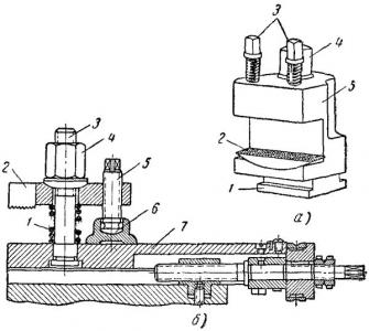
Fig 8 - Toolholders
On small and medium-sized machines, a single tool holder 5 is used (Fig. 8, a). The lower part 1 of the tool holder, which has a T-shape, is fixed on the upper part of the caliper with a nut, 4. To adjust the position cutting edge according to the height of the centers in the tool holder there is a lining 2, the lower spherical surface of which rests on the same surface of the tool holder block. Fix the cutter in the cutter holder with two bolts 3.
On large lathes, single tool holders are used (Fig. 8, b). In this case, the cutter is installed on the surface 7 of the upper part of the caliper and fixed with a bar 2, tightening the nut 4. To prevent the bolt 3 from bending, the bar 2 is supported by the screw 5 resting on the shoe 6. When the nut 4 is unscrewed, the spring 1 lifts the bar 2.
Most often, on medium-sized screw-cutting lathes, tetrahedral rotary cutter heads are used (see Fig. 7).
The cutting head 6 is mounted on the top of the caliper 11; four cutters can be fixed in it with screws 8 at the same time. You can work with any of the installed cutters. To do this, turn the head and put the required cutter in working position. Before turning, the head must be unfastened by turning the handle 9 connected with the nut sitting on the screw 7. After each turn, the head must be clamped again with the handle 9.
- 707 views
We also recommend
 Productive and reproductive thinking
 Reasonable egoism - what is the theory of reasonable egoism?
 Boris Nikolaevich Yeltsin, the first President of Russia
 Underground fights. Underground kings. What is “fighting not for the masses”? Where can you fight for money?
 Yakov Pavlov and Other Heroes of Stalingrad You Need to Know
 Survive an accident at sea in a dream - in reality experience a new love