cutting modes. Feeds during rough turning became carbide cutters without an additional cutting edge. Big encyclopedia of oil and gas
Turning can be carried out with mechanical feed, since the generatrix of the machined cone is parallel to the direction of the longitudinal feed of the cutter.
The copy technological cycle is used for processing stepped, conical and curved surfaces that require a longitudinal feed of the cutter. At the end of surface treatment, the cutter is retracted from the part, and the caliper returns to its original position.
| General index of a thread-cutting machine. |
The longitudinal support 7, mounted on the guides of the bed, moves along them and provides a longitudinal feed of the cutter. The cross carriage provides cross feed to the cutter. The upper rotary support can be set at any angle to the axis of rotation of the workpiece, which is necessary when machining conical surfaces of workpieces.
| Scheme of turning a shaped workpiece. |
After the transverse displacement of the body of the tailstock by an amount h up to 15 - 20 mm), the generatrix of the machined cone is parallel to the direction of the longitudinal feed of the cutter, so turning can be carried out with mechanical feed.
| Scheme of turning cooking. |
After the transverse displacement of the body of the tailstock by the value h (up to 15 - 20 mm), the generatrix of the machined cone is parallel to the direction of the longitudinal feed of the cutter, so turning can be carried out with mechanical feed.
For threading on a lathe, it is necessary that the speed of rotation of the spindle be strictly linked to the speed of movement of the caliper, since the longitudinal feed of the cutter in one revolution of the spindle must exactly match the pitch of the thread being cut.
The thickness of the cut metal layer greatly affects the magnitude of the irregularities. The thickness of the cut layer is determined by the longitudinal feed of the cutter. If there were no elastic-plastic deformations during the cutting process, the height of the irregularities could easily be calculated from geometric shape the top of the cutter.
After 1 minute from the start of work, turn off the longitudinal feed of the cutter, move the cutter away from the workpiece and quickly turn the tool holder by 90 or 180 until the tip of the cutter touches the indicator tip.
For diamonds in a frame, the longitudinal feeds should be less than for pencils, and for cut diamonds even less. For example, when dressing multi-thread thread-grinding wheels with diamond cutters, the longitudinal feed of the cutter should be no more than 0 05 m / min. At the end of the dressing process, it is recommended to make one or two passes without cross feed, reducing the amount of longitudinal feed.
The fixture is designed for boring conical holes with a constant angle a. The device is fixed on the radial support of the machine faceplate. By rotating the screw 3, the cutter is longitudinally fed. At the second end of the screw, an asterisk 1 is installed, which, jumping with its tooth at each turn of the caliper onto the set stop, performs automatic longitudinal feed.
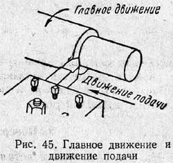
In order to process the workpiece by cutting and obtain as a result of this the machined surfaces of a particular part, the workpiece and the applied cutting tool should make certain movements. These movements are divided into main (serving for the implementation of the cutting process) and auxiliary (serving to prepare for the cutting process and to complete the operation). There are two main movements:
- cutting motion (or main motion);
- feed movement.
When processing on a lathe, the cutting movement - rotational - is performed by the workpiece, which is fastened in one way or another to the machine spindle, and the feed movement - translational - receives a cutting tool (cutter) rigidly fixed in the tool holder. The movement enables the cutting process (chip formation), the movement of the feed makes it possible to conduct this process (processing) along the entire length of the workpiece (Fig. Part 16).
Depth of cut (t)- the value of the cut layer in one pass, measured in the direction perpendicular to the machined surface. The depth of cut is always perpendicular to the feed direction (see also fig. 11-14). With external longitudinal turning (Fig. 16), it is a half-difference between the diameter of the workpiece and the diameter of the machined surface obtained after one pass:
Cutting speedυ - amount of point movement cutting edge relative to the surface per unit time during the implementation of the cutting movement *.
When turning, when the workpiece rotates at a frequency of n rpm, the cutting speed at the MK points of the cutting edge will be a variable value. Max speed:
where D is the largest surface diameter in mm.
* Cutting speed is a function of workpiece rotational speed and tool travel (feed) speed.
If the speed is known, then it is easy to determine the frequency of rotation:
With longitudinal turning, the cutting speed has a constant value throughout the entire cutting time (if the diameter of the workpiece along its entire length is the same, and the rotational speed is unchanged). When trimming the end, when the cutter moves from the periphery of the workpiece to the center, the cutting speed at a constant speed is variable. She has highest value at the periphery and is equal to zero in the center (Fig. 17). The cutting speed will also be variable along the machined surface during parting (see Fig. 14). However, in these cases, consider top speed cutting.

Submission s(more precisely, feed rate) - the amount of movement of the cutting edge relative to the machined surface per unit time in the direction of feed movement. When turning, it can be longitudinal feed when the cutter moves in a direction parallel to the axis of the workpiece (see Fig. 16); cross feed when the cutter moves in a direction perpendicular to the axis of the workpiece (see Fig. 17), and oblique feed- at an angle to the axis of the workpiece (for example, when turning a conical surface).
Distinguish pitch in one turn workpiece, i.e. the amount of relative movement of the cutter during one revolution of the workpiece (from position I the cutter moved to position II, Fig. 16), and minute feed, i.e. the value of the relative movement of the cutter for 1 min. Minute feed is indicated by S m (mm / min), and feed per revolution - s (mm / rev). There is the following relationship between them.
to home
section three
Fundamentals of the theory of metal cutting.
Choice of cutting data
Chapter VI
Fundamentals of the theory of metal cutting
The founders of the theory of cutting metals were the outstanding Russian scientists I. A. Time (1838-1920), K. A. Zvorykin (1861-1928), Ya. G. Usachev (1873-1941) and others. The works of these scientists, which received world recognition have not yet lost their value. However, in the conditions of backward tsarist Russia, all these works did not find practical application because the industry was underdeveloped.
The science of metal cutting gained wide scope only after the Great October Socialist Revolution, especially during the Soviet five-year plans, when science was placed at the service of socialist industry.
Soviet scientists V.D. Kuznetsov, V.A. Krivoukhov, I.M. metals, distinctive feature which is the close collaboration of science with production, scientists with innovators of production.
An important role in the development of the science of cutting metals was played by the movement of innovators in production. In an effort to increase labor productivity, production leaders began to look for new ways to improve cutting conditions: they created a new cutting tool geometry, changed cutting conditions, mastered new cutting materials. Each workplace Turner-innovator has become like a small laboratory for the study of the cutting process.
A broad exchange of experience, possible only in the conditions of a socialist economy, and close cooperation between leading workers in production and science ensured the rapid development of the science of cutting metals.
1. Work of the cutter
Wedge and his work. The working part of any cutting tool is wedge(Fig. 44). Under the action of the applied force, the tip of the wedge cuts into the metal.
The sharper the wedge, that is, the smaller the angle formed by its sides, the less force is required to cut it into the metal. The angle formed by the sides of the wedge is called taper angle and is denoted by the Greek letter β ( beta). Therefore, the smaller the taper angle β, the easier the wedge penetrates into the metal, and, conversely, the larger the taper angle β, the greater the force that must be applied to cut the metal. When assigning the taper angle, it is necessary to take into account the mechanical properties of the metal being processed. If you cut hard metal with a cutter having a small sharpening angle β, then the thin blade will not withstand and will crumble or break. Therefore, depending on the hardness of the metal being processed, an appropriate wedge sharpening angle is assigned.
The layer of metal being processed, located directly in front of the cutter, is continuously compressed by its front surface. When the force of the cutter exceeds the forces of adhesion of metal particles, the compressed element is sheared and shifted by the front surface of the wedge upwards. The cutter, moving forward under the action of the applied force, will continue to compress, chip and shift individual elements from which chips are formed.
Basic movements in turning. When machining on lathes, the workpiece rotates, and the cutter receives movement in the longitudinal or transverse direction. The rotation of the workpiece is called main movement, and the movement of the cutter relative to the part - feed motion(Fig. 45).
2. The main parts and elements of the turning tool
The cutter consists of two main parts: the head and the body (rod) (Fig. 46). Head is the working (cutting) part of the cutter; body serves to secure the cutter in the tool holder.

The head consists of the following elements: front surface, along which the chips come off, and rear surfaces facing the workpiece. One of the rear surfaces facing the cutting surface is called main; the other, facing the treated surface, - auxiliary.
Cutting edges are obtained from the intersection of the front and back surfaces. Distinguish home and auxiliary cutting edge. Most of the cutting work is done by the main cutting edge.
The intersection of the main and secondary cutting edges is called incisor tip.
3. Surface treatment
Three types of surface are distinguished on the workpiece (Fig. 47): machined, machined and cutting surface.

processed surface is the surface of the workpiece from which chips are removed.
Surface treated called the surface of the part obtained after chip removal.
cutting surface called the surface formed on the workpiece by the main cutting edge of the cutter.
It is also necessary to distinguish between the cutting plane and the base plane.
cutting plane called the plane tangent to the cutting surface and passing through the cutting edge of the cutter.
Main plane called a plane parallel to the longitudinal and transverse feeds of the cutter. For lathes, it coincides with the horizontal support surface of the tool holder.
4. Cutter angles and their purpose
The angles of the working part of the cutter greatly affect the flow of the cutting process.
By choosing the right angles of the cutter, you can significantly increase the duration of its continuous operation until blunting (durability) and process per unit of time (per minute or hour) large quantity details.
The cutting force acting on the cutter, the required power, the quality of the machined surface, etc. also depend on the choice of the angles of the cutter. That is why every turner must study well the purpose of each of the sharpening angles of the cutter and be able to correctly select their most advantageous value.
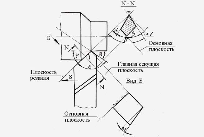
The angles of the cutter (Fig. 48) can be divided into the main angles, the angles of the cutter in the plan and the angle of inclination of the main cutting edge.
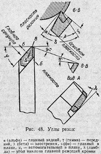
The main angles include: back angle, front angle and taper angle; the angles of the cutter in the plan include the main and auxiliary.
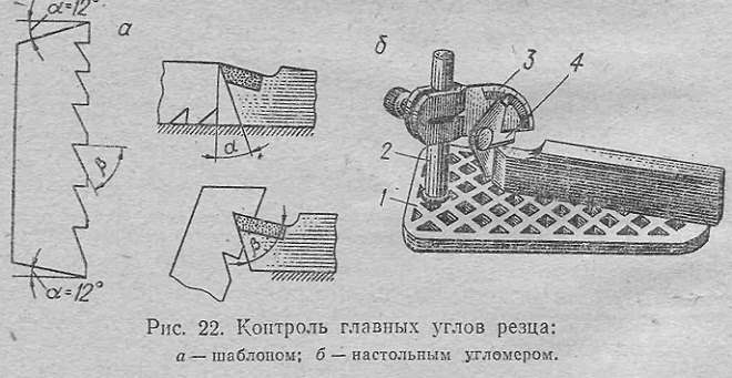
The main angles of the cutter should be measured in the main cutting plane, which is perpendicular to the cutting plane and the main plane.
The working part of the cutter is a wedge (shaded in Fig. 48), the shape of which is characterized by the angle between the front and main rear surfaces of the cutter. This corner is called taper angle and is denoted by the Greek letter β (beta).
back angle α ( alpha) is the angle between the main flank and the cutting plane.
Clearance angle α serves to reduce friction between the back surface of the cutter and the workpiece. By reducing friction, we thereby reduce the heating of the cutter, which, due to this, wears out less. However, if the relief angle is greatly increased, the incisor is weakened and quickly destroyed.
front angle γ ( gamma) is the angle between the front surface of the cutter and the plane perpendicular to the cutting plane, drawn through the main cutting edge.
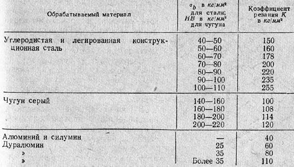
The rake angle γ plays an important role in the chip formation process. With an increase in the rake angle, it is easier to cut the cutter into the metal, the deformation of the cut layer is reduced, the chip flow is improved, the cutting force and power consumption are reduced, and the quality of the machined surface is improved. On the other hand, an excessive increase in the rake angle leads to a weakening of the cutting edge and a decrease in its strength, to an increase in wear of the cutter due to chipping of the cutting edge, and to a deterioration in heat removal. Therefore, when processing hard and brittle metals, to increase the strength of the tool, as well as its durability, cutters with a smaller rake angle should be used; when machining soft and ductile metals, cutters with a large rake angle should be used to facilitate chip removal. In practice, the choice of the front angle depends, in addition to mechanical properties material being processed, from the material of the cutter and the shape of the front surface. Recommended rake angles for carbide cutters are given in Table. one.
Plan angles. Leading angle φ ( fi) is called the angle between the main cutting edge and the feed direction.
The angle φ is usually chosen in the range of 30-90° depending on the type of processing, the type of cutter, the rigidity of the workpiece and the cutter and the method of their attachment. When processing the majority of metals with pass-through peeling cutters, it is possible to take the angle φ = 45°; when processing thin long parts in the centers it is necessary to use cutters with a lead angle of 60, 75 or even 90 ° so that the parts do not bend or tremble.
Auxiliary angle in planφ 1 is the angle between the secondary cutting edge and the feed direction.

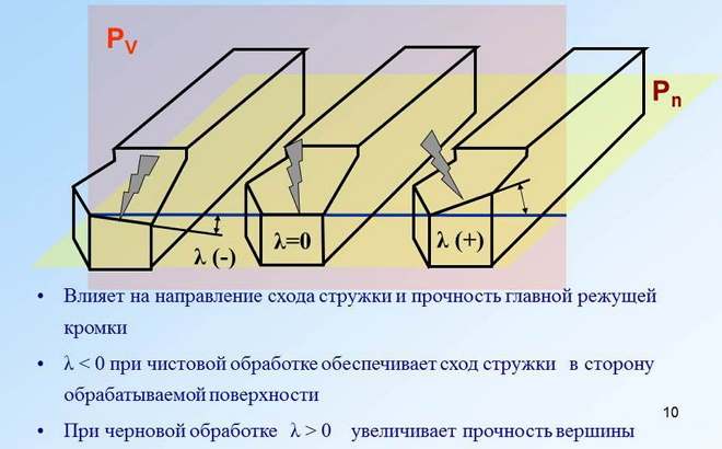
Angle λ ( lambda) inclination of the main cutting edge(Fig. 49) is the angle between the main cutting edge and the line drawn through the top of the cutter parallel to the main plane.
Table 1
Recommended rake and clearance angles for carbide tools
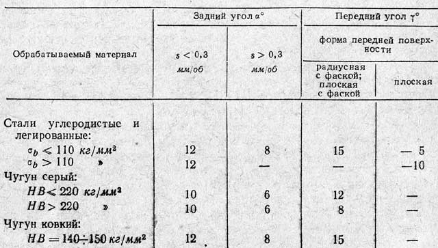 Note. The mechanical properties of metals are determined on special machines and instruments, and each property is given its own designation. The designation σ b given in this and subsequent tables expresses the tensile strength of the metal; the value of this limit is measured in kg/mm 2 . The letters HB denote the hardness of the metal, which is determined on the Brinell device by pressing a hardened steel ball into the surface of the metal. The value of hardness is measured in kg / mm 2.
Cutters whose apex is the lowest point of the cutting edge, i.e. angle λ positive(Fig. 49, c), are more durable and resistant; with such cutters it is good to process hard metals, as well as intermittent surfaces that create an impact load. When processing such surfaces carbide cutters the angle of inclination of the main cutting edge is adjusted to 20-30°. Cutters whose apex is the highest point of the cutting edge, i.e. angle λ negative(Fig. 49, a), it is recommended to use for processing parts made of soft metals.
5. Materials used for the manufacture of incisors
When working on the cutting edges of the cutter, high pressure occurs, as well as high temperature (600-800 ° and above). The friction of the rear surface of the cutter on the cutting surface and chips on the front surface of the cutter causes more or less rapid wear of its working surfaces. Due to wear, the shape of the cutting part changes and the cutter after some time becomes unusable for further work; such a cutter must be removed from the machine and resharpened. To increase the tool life without regrinding, it is necessary that its material resists wear at high temperatures well. In addition, the material of the cutter must be strong enough to withstand high pressures arising during cutting. Therefore, the following basic requirements are imposed on the material of the cutters - hardness at high temperature, good wear resistance and strength.
Currently, there are many tool steels and alloys that meet these requirements. These include: carbon tool steels, high speed steels, hard alloys and ceramic materials.
Carbon tool steel. For the manufacture of cutting tools, steel with a carbon content of 0.9 to 1.4% is used. After quenching and tempering, the cutting tool made of this steel acquires high hardness. However, if during the cutting process the temperature of the cutting edge reaches 200-250 °, the hardness of the steel drops sharply.
For this reason, carbon tool steel is currently of limited use: it is used to make cutting tools that operate at a relatively low cutting speed when the temperature in the cutting zone reaches a small value. Such tools include: dies, reamers, taps, files, scrapers, etc. Cutters are not currently manufactured from carbon tool steel.
High speed steels. High speed steels contain a large number of special, so-called alloying elements - tungsten, chromium, vanadium and cobalt, which give steel high cutting properties - the ability to maintain hardness and wear resistance when heated during cutting to 600-700 °. HSS cutters allow 2-3 times higher cutting speeds than carbon cutters.
At present, the following grades of high-speed steel (GOST 9373-60) are produced in the USSR: R18, R9, R9F5, R14F14, R18F2, R9K5, R9KYU, R10K5F5 and R18K5F2.
Cutters made entirely of high-speed steel are expensive, therefore, in order to save high-speed steel, cutters with welded plates are mainly used.
Hard alloys . Carbide alloys are characterized by very high hardness and good wear resistance.
Hard alloys are made in the form of plates from tungsten and titanium powders combined with carbon. The combination of carbon and tungsten is called tungsten carbide, and with titanium, titanium carbide. Cobalt is added as a binder. This powdery mixture is pressed under high pressure to obtain small plates, which are then sintered at a temperature of about 1500°. The finished plates do not require any heat treatment. The plate is soldered with copper to the cutter holder made of carbon steel or attached to it with the help of adjustments and screws (mechanical fastening of the plates).
The main advantage of hard alloys lies in the fact that they resist abrasion by falling chips and the workpiece well and do not lose their cutting properties even when heated to 900-1000 °. Thanks to these properties, cutters equipped with carbide inserts are suitable for machining the most solid metals(hard steels, including hardened ones) and non-metallic materials (glass, porcelain, plastics) at cutting speeds that are 4-6 times or more higher than the cutting speeds allowed by high-speed cutters.
The disadvantage of hard alloys is increased brittleness.
At present, two groups of hard alloys are produced in the USSR. The main ones are - tungsten(VK2, VKZ, VK4, VK6M, VK6, VK8 and VK8M) and titanium-tungsten(T30K4, T15K6, T14K8, T5K10). Each of these groups has a specific scope (Table 2).
All tungsten alloys are intended for processing cast iron, non-ferrous metals and their alloys, hardened steels, stainless steels and non-metallic materials (ebonite, porcelain, glass, etc.). For the processing of steels, hard alloys of the titanium-tungsten group are used.
Ceramic materials. Recently, Soviet metallurgists have created cheap materials with high cutting properties, which in many cases replace hard alloys. These are ceramic materials thermocorundum), produced in the form of plates white color, reminiscent of marble, which, like hard alloys, are either soldered to the cutter holders or mechanically attached to them. These plates do not contain such expensive and scarce elements as tungsten, titanium, etc. At the same time, ceramic plates have a higher hardness than hard alloys and retain their hardness when heated up to 1200 °, which makes it possible to cut metals with them with high speeds cutting.
The disadvantage of ceramic plates is their insufficient viscosity. Cutters equipped with ceramic inserts can be used for finishing or semi-finishing of cast iron, bronze, aluminum alloys and mild steels.
6. Sharpening and finishing of cutters
In factories, the sharpening of cutters is usually carried out in a centralized manner at grinding machines special workers. But the turner himself must be able to sharpen and finish the cutters.
table 2
Properties and purpose of some grades of hard alloy

Sharpening and finishing of high-speed cutters is carried out in compliance with the following rules:
1. The grinding wheel should not beat, its surface should be even; if the working surface of the circle has developed, it should be corrected.
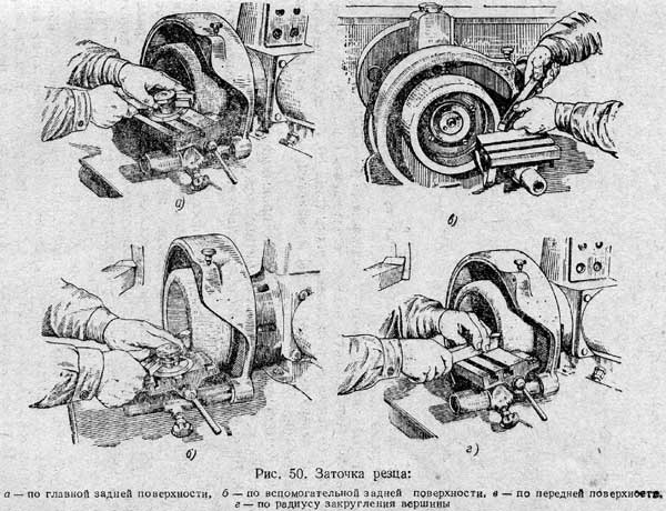
2. During sharpening, you need to use a handpiece, and not hold the cutter on weight. The handpiece should be installed as close as possible to the grinding wheel, at the required angle and give reliable support to the cutter (Fig. 50, a-d).
3. The cutter to be sharpened must be moved along the working surface of the circle, otherwise it will wear unevenly.
4. In order not to overheat the cutter and thereby avoid the appearance of cracks in it, do not strongly press the cutter to the circle.
5. Sharpening must be carried out with continuous and abundant cooling of the cutter with water. Drip cooling, as well as periodic immersion of a highly heated cutter in water, is not allowed. If continuous cooling is not possible, it is better to switch to dry sharpening.
6. Sharpening of cutters made of high-speed steel should be done using electrocorundum wheels of medium hardness and grain size 25-16.
The order of sharpening cutters is set as follows. First, the main back surface is sharpened (Fig. 50, a). Then the auxiliary back surface (Fig. 50, b), then the front surface (Fig. 50, c) and, finally, the radius of the top (Fig. 50, d).
7. It is strictly forbidden to sharpen cutters on machines with the protective cover removed.
8. Be sure to wear safety goggles when sharpening.
After sharpening the cutter, small notches, burrs and risks remain on its cutting edges. They are eliminated by finishing on special finishing machines. Finishing is also carried out manually using a fine-grained whetstone moistened with mineral oil. First, with light movements of the touchstone, the rear surfaces are adjusted, and then the front and the radius of the top.
Sharpening and finishing of cutters equipped with carbide inserts. Sharpening of cutters with plates of hard alloys is carried out on grinding machines with circles of green silicon carbide. Sharpening is carried out both manually (Fig. 50, a-d), and with the fixing of the incisors in the tool holders. The order of sharpening these cutters is the same as for cutters made of high-speed steel, i.e., first the cutter is sharpened along the main back (Fig. 50, a), then along the auxiliary back surfaces (Fig. 50, b), then along the front surface (Fig. 50, c) and, finally, round off the top of the incisor (Fig. 50, d).
Preliminary sharpening is carried out with green silicon carbide wheels with a grit of 50-40, and final sharpening with a grit of 25-16.
The cutter should not be strongly pressed against the working surface of the circle in order to avoid overheating and cracking of the hard alloy plate. In addition, it must be constantly moved relative to the circle; this is necessary for uniform wear of the circle.
Sharpening can be carried out both dry and with abundant cooling of the cutter with water.
After sharpening a carbide cutter, it is imperative to finish its surface. Finishing is done manually or on a finishing machine. Manual finishing is carried out using a cast-iron or copper lap, the working surface of which is rubbed with a special paste or boron carbide powder mixed with machine oil or kerosene is applied to the surface in an even layer. Finishing is carried out to a width of 2-4 mm from the cutting edge.
More productive finishing on a special finishing machine using a cast-iron disk with a diameter of 250-300 mm, rotating at a speed of 1.5-2 m / s; a paste or powder of boron carbide mixed with machine oil or kerosene is applied to the surface of this disk.
7. Chip formation
Types of shavings. The detached chip under the action of the pressure of the cutter greatly changes its shape or, as they say, is deformed: it shortens in length and increases in thickness. This phenomenon was first discovered by Prof. I. A. Time and named chip shrinkage.
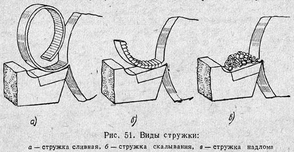
The appearance of the chip depends on the mechanical properties of the metal and the conditions under which cutting occurs. If viscous metals are processed (lead, tin, copper, mild steel, aluminum, etc.), then the individual elements of the chips, tightly adhering to each other, form a continuous chip that curls into a tape (Fig. 51, a). Such a strand is called drain. When processing less viscous metals, such as hard steel, chips are formed from individual elements (Fig. 51, b), weakly connected to each other. Such a strand is called chipping chips.
If the metal being machined is brittle, such as cast iron or bronze, then the individual elements of the chips break and separate from the workpiece and from each other (Fig. 51, c). Such a chip, consisting of individual scales irregular shape, is called broken chips.
The considered types of chips do not remain constant, they can change with changing cutting conditions. The softer the metal being processed and the smaller the chip thickness and cutting angle, the more the chip shape approaches the drain. The same will be observed when cutting speed is increased and cooling is applied. With a decrease in cutting speed, instead of a drain chip, chipping chips are obtained.
Outgrowth. If you examine the front surface of the cutter that was used for cutting, then at the cutting edge you can sometimes find a small lump of metal welded to the cutter under high temperature and pressure. This is the so-called outgrowth(Fig. 52). It appears under certain cutting conditions of ductile metals, but is not observed when processing brittle metals. The hardness of the build-up is 2.5-3 times higher than the hardness of the metal being processed; thanks to this, the growth itself has the ability to cut the metal from which it was formed.
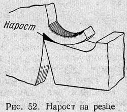
The positive role of the build-up is that it covers the cutting blade, protecting it from wear by descending chips and the action of heat, and this somewhat increases the durability of the cutter. The presence of a build-up is useful when peeling, since the cutting blade heats up less and its wear is reduced. However, with the formation of build-up, the accuracy and cleanliness of the machined surface deteriorate, since the build-up distorts the shape of the blade. Therefore, the formation of build-up is unfavorable for finishing work.
8. The concept of the elements of the cutting mode
In order to perform processing more efficiently in each individual case, the turner must know the basic elements of the cutting mode; these elements are depth of cut, feed and cutting speed.
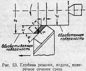
Depth of cut called the distance between the machined and machined surfaces, measured perpendicular to the latter. The depth of cut is indicated by the letter t and is measured in millimeters (Fig. 53).
When turning a workpiece on a lathe, the machining allowance is cut off in one or more passes.
To determine the depth of cut t, it is necessary to measure the diameter of the workpiece before and after the cutter passes, half the difference in diameters will give the depth of cut, in other words, ![]()
where D is the diameter of the part in mm before the cutter passes; d is the diameter of the part in mm after the cutter has passed. The movement of the cutter in one revolution of the workpiece (Fig. 53) is called filing. The feed is denoted by the letter s and is measured in millimeters per revolution of the part; for brevity, it is customary to write mm / rev. Depending on the direction in which the cutter moves relative to the frame guides, there are:
a) longitudinal feed- along the bed guides;
b) cross feed- perpendicular to the bed guides;
in) oblique feed- at an angle to the guides of the bed (for example, when turning a conical surface).
Sectional area of cut denoted by the letter f (eff) and is defined as the product of the depth of cut by the feed (see Fig. 53):
In addition to the depth of cut and feed, they also distinguish the width and thickness of the cut layer (Fig. 53).
Cutting layer width, or chip width, - the distance between the machined and machined surfaces, measured along the cutting surface. It is measured in millimeters and is denoted by the letter b (be).
Cut thickness, or chip thickness, is the distance between two successive positions of the cutting edge in one revolution of the part, measured perpendicular to the chip width. Chip thickness is measured in millimeters and is denoted by the letter a.
With the same feed and depth of cut, as the main angle φ decreases, the chip thickness decreases, and its width increases. This improves heat dissipation from the cutting edge and increases the tool life, which in turn allows you to significantly increase the cutting speed and process more parts per unit time. However, a decrease in the main angle in the plan φ leads to an increase in the radial (repulsive) force, which, when processing insufficiently rigid parts, can cause them to bend, loss of accuracy, and also strong vibrations. The appearance of vibrations, in turn, leads to a deterioration in the purity of the machined surface and often causes chipping of the cutting edge of the cutter.
Cutting speed. When machining on a lathe, point A, located on a circle of diameter D (Fig. 54), in one revolution of the part travels a path equal to the length of this circle.
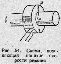
The length of any circle is approximately 3.14 times its diameter, therefore it is equal to 3.14 D.
The number 3.14, showing how many times the length of a circle is greater than its diameter, is usually denoted by the Greek letter π (pi).
Point A in one revolution will make a path equal to πD. The diameter D of the part, as well as its circumference πD, is measured in millimeters.
Assume that the workpiece will make several revolutions per minute. Let us denote their number by the letter n revolutions per minute, or abbreviated as rpm. The path that point A will take in this case will be equal to the product of the circumference and the number of revolutions per minute, i.e. πDn millimeters per minute or abbreviated mm / min, and is called circumferential speed.
Way, passable point the surface to be machined when turning relative to the cutting edge of the cutter in one minute is called cutting speed.
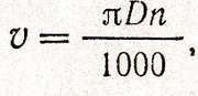
Since the part diameter is usually expressed in millimeters, to find the cutting speed in meters per minute, divide πDn by 1000. This can be written as the following formula:
where v is the cutting speed in m/min;
D is the diameter of the workpiece in mm;
n is the number of revolutions per minute.
Example 3 Processed roller diameter D = 100 = 150 rpm. Determine the cutting speed.
Decision: Spindle speed count. When turning a part of a known diameter, it may be necessary for a turner to adjust the machine to such a number of spindle revolutions in order to obtain the required cutting speed. For this, the following formula is used: ![]() where D is the diameter of the workpiece in mm;
where D is the diameter of the workpiece in mm;
Example 4 What number of revolutions per minute should a roller with a diameter of D \u003d 50 mm have at a cutting speed of v \u003d 25 m / min?
Decision:
9. Basic information about the forces acting on the cutter and cutting power
Forces acting on the cutter. When removing chips from the workpiece, the cutter must overcome the force of adhesion of metal particles to each other. When the cutting edge of the cutter cuts into the material being processed and the chip is separated, the cutter experiences pressure from the metal being separated (Fig. 55).

From top to bottom, the force P z presses on the cutter, which tends to press the cutter down and bend the part up. This force is called cutting force.
In the horizontal plane in the direction opposite to the feed movement, the cutter is pressed by the force P x, called axial force, or feed force. This force during longitudinal turning tends to press the cutter towards the tailstock.
In the horizontal plane, perpendicular to the feed direction, the cutter is pressed by the force P y, which is called the radial force. This force tends to push the cutter away from the workpiece and bend it in a horizontal direction.
All listed forces are measured in kilograms.
The largest of the three forces is the vertical cutting force: it is about 4 times the feed force and 2.5 times the radial force. The cutting force loads the parts of the headstock mechanism; it also loads the cutter, the part, often causing large stresses in them.
Experiments have established that the cutting force depends on the properties of the material being processed, the size and shape of the section of the chip being removed, the shape of the cutter, cutting speed and cooling.
To characterize resistance various materials cutting established the concept of cutting coefficient. The cutting factor K is the cutting pressure in kilograms per square millimeter of the cut section, measured under certain cutting conditions:
Depth of cut t......................5 mm
Feed s......................1 mm/rev
Rake angle γ......................15°
Leading angle φ.......45°
The cutting edge of the cutter - rectilinear, horizontal
The tip of the cutter is rounded with a radius r = 1 mm
Work is done without cooling
In table. 3 shows the average values of the cutting factor for some metals.
Table 3
Average values of the cutting factor K when turning
If the cutting factor K is known, then by multiplying it by the cross-sectional area of the cut f in mm 2, you can find the approximate value of the cutting force using the formula
P z \u003d Kf kg. (eight)
Example 5 A shaft made of machine-made steel with σ b = 60 kg / mm 2 is turned on a lathe. Determine the cutting force if the depth of cut t = 5 mm and the feed s = 0.5 mm/rev.
Decision. According to formula (8), cutting force P z \u003d Kf kg. (eight) We determine the value of f: f \u003d ts \u003d 5x0.5 \u003d 2.5 mm 2. According to the table 3 we find the value of K for machine-made steel with σ b \u003d 60 kg / mm 2: K \u003d 160 kg / mm 2. Therefore, z = Kf = 160x2.5 = 400 kg. cutting power. Knowing the cutting force and cutting speed, you can find out how much power is required to cut chips of a given section.
Cutting power is determined by the formula ![]() (9) where N res - cutting power in hp;
(9) where N res - cutting power in hp;
P z - cutting force in kg;
v - cutting speed in m/min.
The power of the electric motor of the machine tool should be somewhat greater than the cutting power, since part of the power of the electric motor is spent on overcoming friction in the mechanisms that transmit movement from the electric motor to the machine spindle.
Example 6 Determine the cutting power for turning the shaft, considered in the previous example, if the processing is carried out at a cutting speed, υ = 60 m/min. Decision . According to formula (9), cutting power
Cutting power is usually expressed not in horsepower, but in kilowatts (kW). A kilowatt is 1.36 times horsepower, so in order to express power in kilowatts, you need to divide horsepower by 1.36:
and vice versa,
10. Heat of cut and tool life
With an increase in the cutting force, the friction force increases, as a result of which the amount of heat released during the cutting process increases. The heat of cutting increases even more as the cutting speed increases, as this speeds up the entire process of chip formation.
The generated heat of cutting with insufficient removal of it softens the cutter, as a result of which the wear of its cutting part occurs more intensively. This makes it necessary to change the cutter or sharpen it and reinstall it.
The time of continuous work of the cutter before blunting is called the tool life (measured in minutes). Frequent change of cutter (short tool life) causes additional expenses for sharpening and installing the cutter, as well as for replenishing worn cutters.
Therefore, the tool life is an important factor when choosing cutting conditions, especially when choosing cutting speed.
The durability of the cutter depends primarily on the qualities of the material from which it is made. The most resistant will be the cutter, which is made of a material that allows the highest heating temperature without significant loss of hardness. The cutters equipped with hard alloy plates, mineral-ceramic plates have the greatest resistance; significantly less resistance - cutters made of high-speed steel, the smallest - cutters made of carbon tool steel.
The resistance of the cutter also depends on the properties of the material being processed, the cut section, the sharpening angles of the cutter, and the cutting speed. Increasing the hardness of the material being machined reduces the tool life.
By changing the sharpening angles and the shape of the front surface, it is possible to achieve a significant increase in the durability of the cutters and their performance.
Cutting speed has a particularly strong effect on tool life. Sometimes even the slightest increase in speed leads to rapid blunting of the cutter. For example, if, when processing steel with a high-speed cutter, the cutting speed is increased by only 10%, i.e., 1.1 times, the cutter will become dull twice as fast and vice versa.
With an increase in the cross-sectional area of the cut, the tool life decreases, but not as much as with the same increase in cutting speed.
The tool life also depends on the size of the tool, the shape of the cut section and cooling. The more massive the cutter, the better it removes heat from the cutting edge and, consequently, the greater its durability.
Experiments show that with the same section of cut, a large depth of cut and a smaller feed provide greater tool life than a smaller depth of cut with a correspondingly larger feed. This is explained by the fact that with a greater depth of cut, the chips come into contact with a greater length of the cutting edge, so cutting heat is better removed. That is why, with the same cut section, it is more profitable to work with a greater depth than with a greater feed.
The durability of the cutter increases significantly when it is cooled.
Coolant must be supplied plentifully (emulsion 10-12 l/min, oil and sulfofresol 3-4 l/min); a small amount of liquid not only does not benefit, but even spoils the cutter, causing small cracks to appear on its surface, leading to chipping.
11. Choice of cutting speed
Labor productivity depends on the choice of cutting speed: the higher the cutting speed, the less time spent on processing. However, with an increase in cutting speed, the tool life decreases, therefore, the choice of cutting speed is influenced by the tool life and all factors that affect the tool life. Of these, the most important are the properties of the material being machined, the quality of the material of the cutter, the depth of cut, the feed, the dimensions of the cutter and sharpening angles, and cooling.
1. The longer the tool life should be, the lower the cutting speed should be selected and vice versa.
2. The harder the material being processed, the less tool life, therefore, to ensure the necessary resistance when machining hard materials, the cutting speed has to be reduced. When machining cast and forged workpieces, on the surface of which there is a hard crust, shells or scale, it is necessary to reduce the cutting speed against that which is possible when machining materials without crust.
3. The material properties of the cutter determine its durability, therefore, the choice of cutting speed also depends on these properties. Other things being equal, high speed steel cutters allow a significantly higher cutting speed than carbon steel cutters; even higher cutting speeds allow cutters equipped with hard alloys.
4. In order to increase the resistance of the cutter when processing viscous metals, it is advantageous to use cooling of the cutters. In this case, with the same tool life, it is possible to increase the cutting speed by 15-25% compared to machining without cooling.
5. The dimensions of the cutter and the angles of its sharpening also affect the allowable cutting speed: the more massive the cutter, especially its head, the better it removes the heat generated during cutting. Incorrectly selected cutter angles that do not correspond to the material being processed increase the cutting force and contribute to faster wear of the cutter.
6. With an increase in the cut section, the tool life decreases, therefore, with a larger section, it is necessary to choose a cutting speed that is lower than with a smaller section.
Since small chips are removed during finishing, the cutting speed during finishing can be much higher than during roughing.
Since an increase in the cut section has less effect on the tool life than an increase in the cutting speed, it is advantageous to increase the cut section due to a slight decrease in the cutting speed. The processing method of the innovator turner of the Kuibyshev Machine Tool Plant V. Kolesov is based on this principle. Working at a cutting speed of 150 m/min, T. Kolesov finishes steel parts with a feed rate of up to 3 mm/rev instead of 0.3 mm/rev, and this leads to a reduction in machine time by 8-10 times.
The question arises: why do advanced turners often increase labor productivity by increasing cutting speed? Doesn't this contradict the basic laws of cutting? No, it doesn't contradict. They increase the cutting speed only in cases where the opportunities to increase the section of the cut are fully used.
When semi-finishing or finishing is performed, where the depth of cut is limited by a small allowance for machining, and the feed is limited by the requirements of high purity of machining, an increase in the cutting mode is possible by increasing the cutting speed. This is what advanced turners do, working on semi-finishing and finishing. If it is possible to work with large sections cut (with large allowances), then, first of all, it is necessary to choose the greatest possible depth of cut, then the largest possible technologically permissible feed, and, finally, the corresponding cutting speed.
In cases where the machining allowance is small and there are no special requirements for surface finish, the cutting mode should be increased by using the largest possible feed.
12. Cleanliness of the machined surface
When machining with a cutter, irregularities in the form of depressions and scallops always remain on the machined surface of the part, even with the most careful finishing. The height of the roughness depends on the processing method.
Practice has established that the cleaner the surface of the part is treated, the less it is subject to wear and corrosion, and the part is stronger.
Careful surface finishing when machining a part is always more expensive than a rough surface finish. Therefore, the cleanliness of the machined surface should be assigned depending on the operating conditions of the part.
Designation of surface cleanliness in drawings. According to GOST 2789-59, 14 classes of surface cleanliness are provided. To designate all purity classes, one sign is established - an equilateral triangle, next to which the class number is indicated (for example, 7; 8; 14). The cleanest surfaces are graded 14 and the roughest grade 1.
The surface roughness according to GOST 2789-59 is determined by one of two parameters: a) the arithmetic mean deviation of the profile R a and b) the height of the irregularities R z .
To measure the roughness and assign the treated surface to a particular class, special measuring instruments based on the method of feeling the surface profile with a thin diamond needle. Such devices are called profilometers and profilographs.
To determine the roughness and classify the treated surface to one or another class of cleanliness in workshop conditions, tested samples of various classes of cleanliness are used - the so-called purity standards, with which the machined surface of the part is compared.
Factors Affecting Surface Finish. Practice has established that the cleanliness of the machined surface depends on a number of reasons: the material being machined, the material of the cutter, the sharpening angles and the condition of the cutting edges of the cutter, the feed and cutting speed, the lubricating and cooling properties of the liquid, the rigidity of the system machine - cutter - part, etc.
Especially importance to get a surface High Quality when turning, it has a cutting speed, feed, lead angles and a radius of curvature of the tool tip. The smaller the feed and entering angle and the larger the corner radius, the cleaner the machined surface. Cutting speed greatly affects surface finish. When turning steel at a cutting speed of more than 100 m/min, the machined surface is cleaner than at a speed of 25-30 m/min.
To obtain a cleaner machined surface, attention should be paid to careful sharpening and finishing of the cutting edges.
test questions 1. What shape is the chip formed when machining viscous metals? When processing brittle metals?
2. Name the main elements of the incisor head.
3. Show the front and back surfaces on the incisor; front and rear corners; sharpening angle.
4. What is the purpose of the front and rear corners of the incisor?
5. Show lead angles and lead angle.
6. What materials are cutters made of?
7. What grades of hard alloys are used in steel processing? When processing cast iron?
8. List the cutting mode elements.
9. What forces act on the cutter?
10. What factors and how do they affect the magnitude of the cutting force?
11. What determines the durability of the cutter?
12. What factors influence the choice of cutting speed?
The main cutting tools used in the process include a cutter, the geometric parameters of which determine its technical capabilities, accuracy and processing efficiency. Any specialist who decides to devote himself to turning business, insofar as right choice cutting edge angles increases both tool life and productivity.
Parameters of turning tools
Any turning tool form a holder necessary for fixing the tool in the holder lathe, and a working head that provides metal cutting. To consider the geometric parameters of a turning tool, it is better to take a through tool as a sample.
On the cutting part of the turning tool of this type there are three surfaces:
- front (on it during the processing of the workpiece, metal chips are coming off);
- rear - main and auxiliary (both turned with their front part to the workpiece).
The edge of the tool, called the cutting edge (and directly involved in the processing), is formed by the intersection of its front and main rear surfaces. In the geometry of the turning tool, an auxiliary cutting edge is also distinguished. It, respectively, is formed by the intersection of the front surface with the auxiliary back.
The point at which the main and secondary cutting edges intersect is called the tip of the cutter. The latter, when cutting metal, experiences enormous loads, leading to its breakage. To increase the resistance of the tip of the cutter, it is not sharpened during the sharpening process, but slightly rounded. This requires the introduction of a parameter such as the vertex radius. There is another way to increase the resistance of the tip of a turning tool - the formation of a transitional cutting edge that has a rectilinear shape.
The most important geometric parameters of cutters for turning are their angles, which determine mutual arrangement tool surfaces. The angle parameters vary depending on the type of turning tool and on a number of other factors:
- tool material;
- his working conditions;
- characteristics of the material to be processed.
Tool angles for turning
To correctly determine the angles turning tool, them exact values, they are considered in the so-called initial planes.
- The main plane is parallel to the feed directions of the turning tool (longitudinal and transverse) and coincides with its supporting surface.
- The cutting plane includes the main cutting edge and is tangential to the machining surface. This plane is perpendicular to the main one.
- The main cutting plane intersects the main cutting edge and is located perpendicular to the projection that this edge lays on the main plane. There is also an auxiliary secant-type plane, which, accordingly, is perpendicular to the projection deposited on the main plane by the auxiliary cutting edge.
As mentioned above, they are measured precisely in these planes, and those that are measured in a plane called the main secant are designated as the main ones. These are, in particular, the main front, main rear angles, as well as the angles of sharpening and cutting.
One of the most important is the main clearance angle of the turning tool, which minimizes the friction that occurs when the back surface of the tool interacts with the part that is currently being processed (and therefore reduces the heating of the tool and extends its life). This angle is formed by the cutter surface (main rear) and the cutting plane. When choosing this angle when sharpening a tool, the type of processing and the material of the workpiece are taken into account. In this case, you should be aware that a strong increase in the size of the clearance angle leads to a rapid failure of the turning tool.
The strength and durability of the cutting tool, the forces that occur during processing, are determined by the parameters of the rake angle. It is located between the front surface of the turning tool and the plane in which the main cutting edge is located (this plane is perpendicular to the cutting plane). When sharpening a turning tool, a number of factors are taken into account that affect the value of this angle:
- workpiece material and the tool itself;
- the shape of the front surface;
- conditions under which the cutter will be used.

An increase in the value of the rake angle, on the one hand, improves the finish of processing, and on the other hand, it provokes a decrease in the strength and durability of the turning tool. Such an angle, obtained as a result of sharpening, can have a positive and negative meaning.
Turning cutters with rake angles that have negative values are highly durable, but machining with such tools is difficult. Usually sharpening with a rake angle, which has a positive value, is used when the workpiece is to be processed from a viscous material, and also when the tool material is highly durable.
Cutters with negative rake angles are used when machining materials with high hardness and strength, when performing interrupted cutting, when the tool material does not have sufficient bending strength and does not absorb shock loads well.
The parameters that characterize the geometry of the cutter for turning are also cutting and pointing angles. The cutting angle, the value of which can vary within 60–100 0, is located between the surface of the tool, called the front, and the cutting plane.
The value of this angle directly depends on the hardness of the metal being processed: the higher it is, the greater its value. The taper angle is fully consistent with its name, it is measured between the main front and main back surfaces of the tool and characterizes the degree of sharpening of its top.
Characterize the turning tool and the angles in the plan. This is the main one, measured between the direction of the longitudinal feed and the projection that the main cutting edge lays on the main plane, and the auxiliary one, formed by the projection of the auxiliary cutting edge on the main plane and the direction of the longitudinal feed.
When sharpening, these angles are not chosen arbitrarily, but depending on the type of turning and the rigidity that the “machine-tool-workpiece” system has. So, the processing of most metals can be carried out with tools with a main angle in the plan equal to 45 0, but thin and long workpieces should be processed with cutters, in which the value of this angle is in the range of 60–90 0 . This is necessary in order to eliminate deflection and trembling of the part.
The auxiliary angle in the lead simultaneously correlates with the finish of the machining and with the tool life. With its decrease, the cleanliness of processing increases and tool life increases.
In addition to those discussed above, in the geometry of turning tools, angles are distinguished.
Longitudinal turning is called turning, in which the direction of movement of the feed is parallel to the axis of the workpiece. On lathes, the cutting motion - rotation - is attached to the workpiece, and the feed motion - translational movement - to the cutter. On round stick machines, the cutting tool rotates, and the feed motion is attached to the workpiece. The true cutting path is a helical line.
Distinguish between fine and rough turning.
Fine turning (Fig. 2, a) is performed with a cutter with flat working surfaces and straight cutting edges - the main and auxiliary. The position of the cutting edges relative to the axis of rotation of the workpiece is characterized by the main angle in the lead and the auxiliary angle in the lead. The value of the auxiliary angle in the plan determines the depth of the kinematic irregularities, so it cannot be larger. The position of the faces forming the main cutting edge is characterized by the clearance angle, the sharpening angle and the rake angle.
The main cutting edge produces cross-face cutting, characterized by the angle of inclination of the wood fibers.
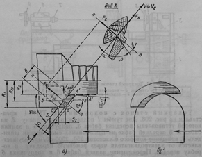
Rice. 2. Longitudinal turning finishing (a) and roughing (b)
The angle of inclination is measured between the direction of the fibers and the normal.
Rough turning (Fig. 2, b) is carried out with grooved cutters with a semicircular cutting edge. Transverse section the chips are sickle-shaped, the thickness of the chips at the periphery of the workpiece is maximum, and near the surface of the part it is insignificant even at high feed to the cutter. This allows you to apply the feed per cutter up to 2 mm, while for fine turning - no more than 0.8 mm.
> Setting up lathes
When setting up lathes, it is necessary to: select a cutter and fix it in the tool holder (for machines with mechanical feed); install a faceplate or chuck; select and fix the hand rest (for machines with manual feed) or a copy ruler (for machines with mechanical feed); install and fix the workpiece in the machine; test the machine at idle; set the spindle speed and feed rate; process and inspect test pieces.
The required cutter is selected depending on the nature of the work performed. For the initial roughing, a peeling cutter is used, for the final one, a finishing cutter with a straight cutting edge. With mechanical feed, the cutter is fixed in the tool holder with screws. To reduce the changeover time, special rotary heads are used, where several incisors for various purposes are simultaneously strengthened.
At manual work it is necessary to check the reliability of fastening the cutter to the wooden handle. Do not use a defective cutting tool.
The means of fastening the workpiece are selected depending on its shape and size. For fastening long workpieces (Fig. 3, a), front and rear centers are used. The front center 2 is made in the form of a three-pronged leash with a tapered shank, with which it is inserted into the tapered hole of the spindle 1. The rear center 4 has a conical and pointed part and is fixed in the quill 5 of the tailstock 6. To reduce friction and increase the reliability of fastening the workpiece, the rear center is mounted on bearing, which ensures its rotation with the workpiece 3.

Rice. 3. Fastening the workpiece in lathes: a - in the centers, b - in the chuck, c - on the faceplate; 1 - spindle, 2 - front center, 3 - workpiece, 4 - rear center, 5 - quill, 6 - tailstock, 7 - chuck, 8 - plan
Depending on the length of the workpiece being processed, the tailstock is moved along the guides of the bed and fixed in a predetermined position. The workpiece is fixed by pushing the quill out of the headstock until the centers are embedded in the ends of the workpiece and will securely hold it during rotation. To turn taper parts, the tailstock housing should be moved transversely with an adjusting screw and fixed with a locking device. Chucks are designed for fastening short workpieces (Fig. 3, b). Chuck 7 has a thread through which it is screwed onto the spindle. The workpiece is fixed in the chuck by firmly fitting its end into the chuck hole. Collet chucks and chucks with sliding jaws are also used.
For clamping workpieces of short length and large diameter serve as faceplates 8 (Fig. 3, c), screwed onto the spindle. The workpiece is fixed to the faceplate with screws or bolts 9.
The handpiece is installed on the frame so that its working edge is at the level of the centers and is near the generatrix of the workpiece being processed, but does not touch it. As the diameter decreases and when processing long workpieces, the handpiece is sequentially rearranged to a new position along the bed guides. When processing shaped products on the back side of the bed, a copy ruler is fixed on the brackets, the shape of which is similar to the shape of the finished part. When the feed is turned on, the caliper moves along a curved path and the cutter reproduces the given shape of the part.
The spindle speed is selected depending on the diameter of the workpiece and its strength. For larger diameters, the minimum spindle speed should be set. When installing a faceplate with a diameter of 400 mm, the spindle speed should not exceed 800 rpm. The rotational speed is reduced by the gear shift lever or by changing the rotational speed of the multi-speed electric motor. cutting speed for wood soft rocks should be 10 ... 12 m / s, solid - 0.5 ... 3 m / s.
Longitudinal feed per one revolution of the spindle should be: for roughing 1.6 ... 2 mm, for finishing - no more than 0.8 mm. The higher the requirements for surface roughness, the lower the longitudinal feed should be. Cross feed per spindle revolution should not exceed 1.2 mm. Before starting the machine, make sure that reliable fastening blanks and install a fence.
After roughing the part, the cutter is replaced and fine turning is performed at low feed. The chips in this case should be as continuous as possible and of uniform thickness.
During processing, the shape of the part is periodically controlled by a template or gauge. When using a caliber or measuring tool with a scale, the machine is turned off and only after the part has completely stopped, it is measured.
Having finished the adjustment, a trial processing of the part is carried out and its dimensions are controlled with a caliber or a measuring tool with a scale.
We also recommend
 Switching power supply: repair and refinement
 Remote control of light
 Swimming lessons for preschool children
 Notes for the master - home household alarms
 Clock propeller on Atmega8
 Device and relay application examples, how to choose and connect a relay correctly Microcontroller and relay simple switching circuits