FU450MRApUG wide universal milling machine
Send your good work in the knowledge base is simple. Use the form below
Students, graduate students, young scientists who use the knowledge base in their studies and work will be very grateful to you.
Posted on http://www.allbest.ru/
Introduction
1. General part
1.1 Purpose and devices of the workshop
2. Special part
2.1 Purpose and device of the console-milling universal machine 6E80Sh
2.3 Lubrication of the console-milling universal machine model 6E80Sh
3. Organization of production
3.1 Technical documentation for overhaul console-milling universal machine model 6E80Sh
3.2 Statement auxiliary equipment, fixtures and tools for the overhaul of the console-milling universal machine model 6E80Sh
4. Economic part
4.1 Time limits for the overhaul of the console-milling universal machine model 6E80Sh
4.2 Tariff rates in the shop
5. Measures for safety and fire fighting equipment
5.1 Labor protection at the site
5.2 Safety
5.3 Industrial sanitation
5.4 Fire protection
5.5 Environmental protection
Bibliography
Introduction
ArcelorMittal is the largest steel company in the world, controlling 10% of the world steel market at the end of 2008. Registered in Luxembourg.
It was formed in 2006 by the merger of Luxembourg-based Arcelor and Indian Mittal Steel, owned by Indian businessman Lakshmi Mittal.
After the merger, the company's production capacity amounted to 120 million tons per year. The development goal was announced to increase the capacity over the next five years to 150 million tons. Economic crisis led to the postponement of ongoing projects from 2011-2012 to 2014.
Joint Stock Company "ArcelorMittal Temirtau" is largest enterprise mining and metallurgical sector of the Republic of Kazakhstan and is an integrated mining and metallurgical complex with its own coal, iron ore and energy base.
ArcelorMittal Temirtau JSC includes:
Steel Department;
Coal Department;
iron ore department.
JSC "ArcelorMittal Temirtau" specializes in the production of flat and long products, including those with polymer, zinc and aluminum coated, and also produces sinter, iron ore and coal concentrate, coke, pig iron, steel, including continuously cast slabs, strip, spar strip, electrowelded pipes and related products of blast-furnace and coke industries.
ArcelorMittal Temirtau JSC is a socially oriented company. On the balance sheet of the enterprise there are rest houses, sanatoriums, children's summer camps recreation, sports facilities and medical institutions. The company is a supplier utilities(hot and cold water, heating, electricity) to residents of Temirtau.
cantilevered technological milling machine
1. General part
1.1 Purpose and arrangement of the workshop
Shop Passport No. 31
The workshop was designed by the Karaganda branch of Gipromez in 1957, built and put into operation by the Kazmetallurgstroy trust in September 1970 (without an administrative building).
The workshop was intended for carrying out repairs of equipment for sintering, steelmaking and foundries. In October 1971, the workshop was reorganized in connection with the creation of an independent structural subdivision of TsRMO-1.
TsRMO-2 is designed for repairs of steel-smelting shops equipment, manufacturing and restoration of spare parts, blast furnace tuyeres, converter lance heads, manufacturing and restoration of steel-pouring ladle locking rods.
The workshop consists of two repair sections (open-hearth and converter) and a repair and mechanical workshop.
The workshop is located in a two-bay building 96 meters long and 18 meters wide, with a total area of 3460 square meters.
Intra-workshop transportation of goods is carried out by three electric overhead cranes with a lifting capacity of 5 tons, two cranes with a lifting capacity of 15/3 tons, an electric trolley with a lifting capacity of 10 tons, two electric cars and two electric loaders.
External cargo turnover is carried out by rail and road transport.
The workshop has three road entrances and a railway access track with a length of 18 m. All workshop entrances are equipped with air curtains.
The workshop is heated by 5 STD-300 units.
The project provides:
1. Removal of products from 1 total area workshops - 0.68 t/year
2. Removal of products from one main machine - 88.5 t / year
3. Production of products per machine operator - 54.5 tons / year
4. Output of products per worker - 22.6 tons / year.
Productive capacity
|
Name |
Annual release |
||||
|
By project |
In fact, as of January 1, 1972 |
||||
|
Spare parts machining |
|||||
|
Machining of re-repairable spare parts |
|||||
|
Machining stop rods |
|||||
|
Tuyere repair |
|||||
|
Repair and installation works |
TECHNOLOGICAL PROCESS.
The technological process of processing spare parts is individual and small-scale. Casting, forgings and sectional metal for the manufacture of spare parts comes to the workshop from the warehouses of the OTS and the procurement workshops of the chief mechanic's department. The repair technology consists in assembly and revision of units during the preparation of repairs, replacement of units, individual parts and revision of units during the period of repair.
The workshop is set to work in two shifts, with a shift duration of 8.25 hours with a five-day working week with two days off.
1.2 Purpose and summary technical specifications main equipment
CHARACTERISTICS OF AREAS AND REPAIR AND MECHANICAL WORKSHOP.
The area for the repair of open-hearth shop equipment - performs scheduled preventive repairs of equipment in accordance with approved schedules in the open-hearth, refractory and composition preparation shops.
The site is located in the premises of the open-hearth shop.
The site includes 7 teams (60 people) of repair fitters, electric and gas welders and cutters.
The area for the repair of equipment of the converter shop - performs scheduled preventive repairs of equipment in accordance with the approved schedules in the converter and pile driver shops.
The site is located in the built-in room of the main building of the converter shop on area 60, at 23 mark.
The site includes 7 teams (62 people) of repair fitters, electric and gas welders and cutters.
Repair and mechanical workshop.
Located in the production building of the workshop. The repair and mechanical workshop includes:
A) mechanical department;
B) locksmith and assembly department;
C) forging and welding and procurement department;
D) department for the manufacture and restoration of locking rods;
D) electromechanical service.
The mechanical compartment is intended for mechanical processing of spare parts. It is located in span AB on an area of 48 square meters. The number of machine tools is installed in the department, based on the complexity of processing one ton of products - 90 machine hours.
The locksmith and assembly department is intended for the assembly and revision of equipment units of the steel-smelting shops of the plant. The department is located in the span AB and BV on area 972. The department consists of 2 teams (10 people) of locksmiths.
The Forge-Welding and Procurement Department is designed for the manufacture of small forgings and tool blanks, cutting of blanks from rolled products of various profiles and the manufacture of copper tuyeres of the open-hearth and converter shops. The department with a metal warehouse is located in the AB bay on the area 648.
The department for the production and restoration of stop rods is intended for the production of stop rods for steel-pouring ladles. Works are carried out on a production line with a capacity of 1600 tons of locking rods per year.
Currently, the design of the department is being reviewed in order to improve the technological process for the manufacture of stop stubble.
The electromechanical service is intended for carrying out scheduled preventive repairs and troubleshooting the equipment of a mechanical workshop. The service is located in the BV bay in a built-in room with an area of 180 square meters. The service consists of 4 electricians and 6 locksmiths.
The material warehouse is located in the BV bay in a built-in room with an area of 24 square meters. The warehouse is intended for storage of material and technical assets. Works on the transportation of goods in the warehouse are carried out manually.
The spare parts warehouse is located in the span of the BV on area 24, fenced metal mesh. The warehouse is serviced by an electric forklift with a carrying capacity of 5 tons.
POWER SUPPLY OF THE SHOP.
The workshop is supplied with electricity from 12 substations with a 10 kV cable. A step-down transformer 1000 kVA, 10/0.4 kV is installed in the workshop.
General electric power workshops - 660 kW.
Including power - 440 kW;
crane - 184 kW;
electric furnace - 8 kW;
electric welding - 28 kW.
The intrashop networks are connected to the NTP 0.4 kV, the wiring is made in pipes with APR type wire. On all boards ShR and ShchU automatic machines of the A3124 and A3131 types are installed.
Lighting in the workshop is made by GE-50 lamps in the amount of 87 lamps. The total electrical power of the fixtures is 43.5 kW.
Intrashop networks
|
Name |
Insert location |
Intrashop network |
||||
|
diameter mm |
number |
|||||
|
gas pipeline |
General plant highway |
|||||
|
Oxygen pipeline |
||||||
|
Steam pipeline |
||||||
|
Compressed air pipeline |
||||||
|
Hot water pipeline |
||||||
|
Household drinking water supply |
||||||
|
Process water pipeline |
AUTOMOTO TRANSPORT
For intra-shop and intra-plant transportation, the workshop has 2 electric forklifts EP-301 with a universal fork grip with a lifting capacity of 3 tons and 2 electric cars EK-2 with a lifting capacity of 2 tons.
SANITARY AND HOUSEHOLD CONDITIONS.
The administrative building of the workshop is under construction. The personnel of the repair and installation teams are temporarily located in the administrative building of the open-hearth and converter shops.
Technical characteristics of the equipment
|
Name, type, model, manufacturer |
Technical specifications |
|||
|
MECHANICAL COMPARTMENT |
||||
|
Console- milling machine 6M12P (Gorky Machine Tool Plant) |
Distance from spindle nose to table: The smallest - 30 mm; The largest is 400 mm. The size of the working surface of the table is 1250×320 mm. The largest movements of the table: Longitudinal - 700 mm; Transverse - 260 mm; Vertical - 370 mm. Spindle inner taper - B 3 The largest angle of rotation of the spindle head is ±45°. The largest axial movement of the spindle is 70 mm. Spindle speed limits 31.5h1600 rpm. |
|||
|
Wide-universal console milling machine 6M82Sh |
Dimensions of the working surface of the table - 125x320 mm. Mandrel diameter - 32 mm; 50 mm. Number of spindles - 2. Spindle taper: Horizontal - No. 3. Rotary and laid on heads - No. 2. Spindle speed limits: Horizontal 31.5h1600 rpm; Swivel head 90-1400 rpm. Limits of longitudinal and transverse table feeds: 25h1250 mm/min. The limits of the vertical feed of the table are 8.3-416.6 mm. The longitudinal course of the table is 700 mm. The transverse course of the table is 240 m. The vertical course of a table - 420 mm. Rotation of the milling head in the transverse plane of the table - 45-90°. The maximum weight of the processed detail - 250 kg. |
|||
|
Hydroficated cross planer 7M37 (Gomel Machine Tool Plant) |
Slider travel - 150x100 mm. Table dimensions - 560x1000 mm The greatest distance between the plane of the table and the slider is 500 mm. The greatest horizontal movement of a table - 800 mm. The slider speed limits are 3h48 m/min. The largest angle of rotation of the cutting sled is ±60°. |
|||
|
Hydroficated slotting machine 7M430 (Gomel Machine Tool Plant). |
Cutter stroke - 320 mm Table rotation - 360° Table diameter - 700 mm Maximum table travel: Longitudinal - 600 mm Cross - 300 mm. The cutter speed limits are 3h24 m/min. |
|||
|
Longitudinal planer 7210 (Minsk Machine Tool Plant) |
The distance between the table surface and the crossbar is 1000 mm. Distance between racks - 1100 mm Table dimensions: 3000x900 mm. Table travel length: The largest - 3200 mm; The smallest is 700 mm. Number of calipers: On the crossbar - 2; On the rack - 1. Horizontal movement of calipers along the crossbar - 1500 mm. Vertical movement of a support on a rack - 900 mm. Speed of the working course of a table - 4h90 m/min. Table reverse speed - 12h90 m/min. |
|||
|
Carousel machine 1531 (Krasnodar Machine Tool Plant). |
Faceplate diameter - 1150 mm Faceplate revolutions - 6.3h315 rpm. The tilt angle of the vertical caliper is ±45°. The height of the vertical support lift is 550 mm. move cross caliper- 630 mm Caliper feed - 0.05x12.5 mm / rev. |
|||
|
Horizontal boring machine 2620V (Leningrad machine-tool association named after Sverdlov). |
Spindle diameter - 90 mm. Spindle speeds - 12.5h2000 rpm. Faceplate rotation speeds - 8h200 rpm. The inner taper of the spindle is Morse No. 5. Dimensions of the working surface of the table - 1120x1300 mm. Maximum travel: Headstock vertical - 1000 mm; Spindle length - 710 mm; Table across - 1000 mm; Table lengthwise - 1090 mm; Faceplate support radial - 170 mm. The largest diameter of the boring hole: Spindle - 330 mm; Caliper - 600mm. |
|||
|
Radial drilling machine 2H55 (Odessa Machine Tool Plant). |
The largest drilling diameter is 50mm. Morse taper - No. 5. The largest axial movement of the spindle is 350 mm. Spindle overhang - 410h1600 mm. Spindle speed - 20-2000 rpm |
|||
|
Screw-cutting lathe 1E61M (Izhevsk Machine Tool Plant) |
The height of the centers is 170 mm. The hole in the spindle is 32 mm. Above the caliper - 183 mm; Above the bed - 320 mm. |
|||
|
Screw-cutting lathe 1K62 (Efremov Machine-Tool Plant, Moscow) |
The height of the centers is 215 mm. Spindle hole - 38 mm Largest workpiece diameter: Above the caliper - 260 mm; Above the bed - 400 mm. |
|||
|
Screw-cutting lathe 1625 (Efremov Machine-Tool Plant, Moscow) |
Distance between centers - 1400 mm. The height of the centers is 215 mm. Spindle bore - 47 mm. Largest workpiece diameter: Above the caliper - 260 mm; Above the bed - 400 mm. |
|||
|
Screw-cutting lathe 1A616 (Kuibyshev Machine Tool Plant). |
Distance between centers - 710 mm. The height of the centers is 170 mm. The hole in the spindle is 32 mm. Largest workpiece diameter: Above the caliper - 188 mm; Above the bed - 320 mm. |
|||
|
Screw-cutting lathe 163 (Tbilisi Machine Tool Plant) |
Distance between centers - 1400 mm. The height of the centers is 265 mm. Spindle bore - 65 mm. Largest workpiece diameter: Above the caliper - 350 mm; Above the bed - 630 mm. |
|||
|
Screw-cutting lathe 9H14S3 (Tbilisi Machine Tool Plant) |
Distance between centers - 710 mm. The height of the centers is 265 mm. Spindle bore - 65 mm. Largest workpiece diameter: Above the caliper - 350 mm; Above the bed - 630 mm. |
|||
|
Screw-cutting lathe 165 (Ryazan Machine Tool Plant) |
Distance between centers - 2800h5000 mm. The height of the centers is 500 mm. The hole in the spindle is 80 mm. Largest workpiece diameter: Above the caliper - 650 mm; Above the bed - 1000 mm. Spindle speed - 5h500 rpm. |
|||
|
Circular grinding machine ZA164A (Kommunar plant, Lubny, Poltava region) |
Distance between centers - 2800 mm. The largest diameter of the product is 400 mm. The maximum weight of the product is 250 kg. Dimensions of the largest circle: Outer diameter - 750 mm; Internal diameter - 40 mm; Width - 70 mm. |
|||
|
FITTING AND ASSEMBLY DEPARTMENT. |
||||
|
Horizontal hydraulic press P983 (Odessa plant of presses). |
Force - 315 t. Liquid pressure in the network - 200 kg/cm². The largest stroke of the plunger is 850 mm. The maximum diameter of the pressed product is 1500 mm. The working fluid is oil. Distance from the end of the plunger to the end of the movable thrust beam: Maximum - 2900 mm; Minimum - 900 mm; Working - 2500 mm. |
|||
|
Single-column hydraulic press P6320 (Orenburg Metalist plant). |
Force - 10 t. Liquid pressure in the network - 160 kg/cm². Stroke - 400 mm. Table dimensions - 380x500 mm. |
|||
|
Peeling and grinding machine ZM-634 (Jalal-Abad repair plant) |
Number of laps - 2 Circle sizes - 400x40x203 mm Spindle speed - 1420 rpm. Distance between centers - 700 mm Center height - 830 mm |
|||
|
Vertical drilling machine 2A135 (Plant named after Lenin, Sterlitomak). |
The maximum drilling diameter is 35 mm. Spindle taper - Morse No. 4. Departure of an axis of a spindle - 300 mm. Spindle travel - 225 mm. Headstock stroke - 200 mm. Spindle speed - 68-1100 rpm. Feed range - 0.12h1.6 mm / rev. |
|||
|
Forging and welding and procurement department. |
||||
|
Pneumatic forging hammer М415А (Voronezh plant KPO). |
The weight of the feeding parts is 400 kg. The number of beats per minute - 130 The effective kinetic energy of the feeding parts is 950 gm. Distance from an axis of the woman to a bed - 520 mm. The distance from the mirror of the striker to the woman is 530 . Dimensions of the striker mirror - 265x100 mm. Optimal forged section of the workpiece: Square - 100 mm; Round - 115 mm. |
|||
|
Cutting hacksaw 872 (Krasnodar Experimental Plant named after Kalinin). |
Saw frame travel length - 140x180 mm. Blade length - 450 mm The number of strokes of the saw frame per minute - 85-110. |
|||
|
Milling and cutting machine 8V66 (Minsk Machine Tool Plant) |
The number of revolutions of the saw blade in min. - 3.3h25.5 Saw blade diameter - 710 mm. Cutting speed - 7.4h57 m/min. The largest diameter of the workpiece being cut is 230 mm. |
|||
|
Welding converter PSO-300 |
Current regulation limits: |
|||
|
Welding transformer TD-500 (factory mailbox M-5293) |
||||
|
Forge forge |
Made by the workshop. |
|||
|
Heating chamber furnace |
The hearth area is 0.66 m². Fuel: coke oven gas. |
|||
|
ELECTRO-MECHANICAL SERVICE. |
||||
|
Vertical drilling machine 2A125 (Mechanical plant, Kabanye village, Luhansk region). |
The largest drilling diameter is 25 mm. Spindle travel - 200 mm. Spindle rpm - 165h2130. The greatest movement of a table - 400 mm. Table dimensions - 350x400 mm. |
|||
|
Peeling and grinding machine 3M-634 (Mukachevo plant named after Kirov) |
Number of circles - 2. The sizes of circles - 400×40×203 mm. Spindle revolutions in min. - 700h1400. |
|||
|
Surface grinding machine 372B (Moscow Machine Tool Plant). |
Dimensions of workpieces - 1000x300x400 mm. Table dimensions - 1000×300 mm. Circle height - 40 mm. Circle diameter: Outer - 250h350 mm; Internal - 127 m. |
|||
|
Universal grinding machine 3659A (Vitebsk plant of grinding machines). |
The diameter of sharpened drills, zinkers is 80 mm. Sharpening angles - 70°h140°. The number of feathers of the sharpened tool is up to 12. Grinding wheel: Outer diameter - 200 mm; Internal - 32 m; Height up to - 70 mm. The number of revolutions of the circle in min. - 1850 |
Handling equipment
|
Name, No., manufacturer |
Installation Location |
Technical specifications |
|||
|
Bridge electric crane No. 1 (Mechanical plant, settlement Novobureisk, Khabarovsk region). |
Forging department Mechanical department. Stopper rod manufacturing department |
Load capacity - 5 tons. The length of the bridge is 16.5 m. Movement speed: Crane - 73.5 m / min; Carts - 38 m/min; Lifting - 10 m/min. Lifting height - 8 m. |
|||
|
Bridge electric crane No. 3 (Machine-building plant, Uzlovaya station, Tula region). |
Fitting and assembly department |
Load capacity - 15/3 t. The length of the bridge is 16.5 m. Movement speed: Crane - 49 m/min; Carts - 18 m/min; Main lift - 2.2 m/min; Auxiliary lifting - 9.7 m / min. lift height: Main - 8.5 m; Auxiliary - 8.5 m. |
|||
|
Bridge electric crane No. 4 (PTO plant, Alexandria, Kirovograd region). |
Fitting and assembly department |
Load capacity - 15/3 t. The length of the bridge is 16.5 m. Movement speed: Crane - 75.3 m / min; Carts - 34.5 m / min; Main lift - 8 m/min; Auxiliary lifting - 19.2 m / min. lift height: Main - 8 m; Auxiliary - 8 m. |
|||
|
Trolley electric (Dnepropetrovsk plant of metallurgical equipment). |
Between spans in axes 4-5 |
Load capacity - 10t; Rail track - 1000 mm; Trolley base - 1600 mm. Platform size - 2630×1650 mm. Travel speed - 40 m/min. Drive from the MTK-11-V electric motor, Power 2.2 kW, 885 rpm. Button control. |
2. Special part
2.1 Purpose and device of the console-milling universal machine model 6E80Sh
Figure 2.1.1 Console-milling universal machine model 6E80Sh
Shirokouniversalny cantilever-milling horizontal machine 6E80Sh is designed to perform milling and some types of boring work on parts small size from ferrous and non-ferrous metals and plastics.
Are applied in the conditions of single and mass production. The technical characteristics of the machines make it possible to fully utilize the capabilities of high-speed steel tools, as well as tools equipped with carbide inserts.
Swivel milling head with retractable quill allows milling inclined surfaces of workpieces. The use of a dividing head, a rotary table, a vice expands the technical capabilities of the machine.
The machines work on the principle of milling with a rotating fixed cutter fixed in a horizontal or vertical spindle. Movements of the table (X-coordinate), slide (Y-coordinate), console (Z-coordinate) are used as working or installation movements.
The use of CNC equipment allows you to process parts according to the program in automatic mode.
Design features:
The rack is the base unit on which all other units and mechanisms are mounted. The rack is rigidly connected to the plate (base). A vertical spindle head is mounted on the trunk of the machine, and suspension brackets are attached to the trunk guides for working with long mandrels.
The gearbox of the horizontal spindle is rack mounted. The vertical spindle is driven by an electric motor placed on top of the head.
The rear wall of the console is made in the form of dovetail guides. The sled moves transversely on the console and has guides for the table. A longitudinal feed screw is connected to the table. Work is possible both by the method of associated and by the method of counter milling.
Machine composition:
The mechanism for switching the vertical movement of the table, slide, table, cooling system, electrical cabinet, mechanisms for switching the transverse movement of the table, bed, feed box, feed switching mechanism, horizontal spindle speed switching mechanism, gearbox and spindle, trunk with a spindle head, protective device, mechanism for switching the rotational speed of the vertical spindle, suspension, console.
Devices and operation of the machine and its main parts.
Controls and their purpose:
Handle of manual vertical stirred table
Flywheel for manual cross movement of the sled
Vertical feed enable lever
Worm for backlash sampling on a longitudinal screw
Flywheel manual movement table
Table clamp
Switch "Lighting"
Spindle sleeve clamp handle
Cooling valve
Power switch handle
Table fast move button
Start button
"Stop" emergency button
Slider clamp handle
Cross feed enable lever
Console clamp handle
Feed motor switch
Cooling pump switch
Horizontal spindle rotation direction switch
Push button
Vertical spindle rotation direction switch
Horizontal spindle override lever
Horizontal spindle gear lever
Manual movement of the trunk
Trunk clamp on the frame
Clamping the milling head to the trunk
Worm turning the milling head in the longitudinal plane of the table
Worm turning head milling in the transverse plane of the table
Vertical spindle override handle
Vertical spindle pulley switching knob
Vertical spindle gear selector
Handle for moving the sleeve of the vertical spindle
Lever for longitudinal feed
Gear shift handle
Feed shift lever
Screws for clamping the sled of the machine 6T80
Stop button
Kinematic scheme.
The spindles are driven by electric motors through a V-belt transmission.
Spindles have 12 different speeds obtained by moving gear blocks along splined shafts. The feed wire is carried out from the electric motor through the coupling, from the shaft IX to the feed box. By moving the gear blocks, the feed box provides 18 different feeds, which are transmitted to the XUI shaft of the console and then, when the corresponding cam clutch is turned on, to the screws of longitudinal, transverse and vertical movement.
Accelerated movements are carried out from the electric motor through the shafts IX, X, KhP, XU, electromagnetic and overrunning clutch to the shaft CL of the console.
The inclusion and reversal of longitudinal, transverse, vertical feeds is carried out by double-sided cam clutches.
The bed is base part machine on which all other components and mechanisms are mounted. The stand of the bed is rigidly connected to the plate (base), which is the reservoir of the coolant.
A vertical spindle head is mounted on the trunk of the 6E80Sh machine, and suspension brackets are attached to the trunk guides for working with long mandrels. Suspensions have a rolling bearing and a sliding bearing. The hangers on the machines are not interchangeable; to install the hangers, turn the head up.
The gearbox of the horizontal spindle is mounted in the frame. The connection to the electric motor is carried out through a V-belt transmission. Inspection and access to the gearbox - through the window of the gearshift unit on the virgin side of the bed. The drive of the vertical spindle of the machine is carried out from an electric motor placed on top of the head through a V-belt drive, a roller clutch and a gearbox.
The spindle is mounted in a sliding sleeve. The spindle head of the 6E80Sh machine is attached to the trunk through a clamp and can be rotated in the transverse and longitudinal directions of the table. The feed drive is located in the console. In front, a flanged electric motor is built into the lower part of the console, a feed box with a feed switching mechanism and a mechanism for turning on the vertical movement of the table is mounted on the left side of the console, on the right - a mechanism for turning on the transverse movement of the table. The eighteen-speed feed box has a fast travel chain with a safety clutch that eliminates the possibility of damage to the feed drive during overloads.
An electromagnetic clutch and an overrunning clutch are mounted on the same shaft with a safety clutch. Turning on the fast movements of the table is carried out by the button. The feed switching mechanism consists of cam handles with profile grooves, a limb and levers for switching gears.
Switching gears of the feed box occurs when the limb rotates around the axis and when the axis rotates with the handle.
The inclusion of vertical and transverse mechanical movements of the table is carried out by handles. The direction of movement of the handles is mnemonically linked to the direction of movement of the table.
Manual vertical movement of the table is carried out by a handle, transverse - by a flywheel.
The rear wall of the console is made in the form of dovetail guides.
The upper part of the console has rectangular rails along which the sled moves.
The sled moves transversely on the console and has guides for the table.
A longitudinal feed screw is connected to the table. In the sled there are bevel gears that rotate the screw, handles and a mechanism for turning on the longitudinal feed.
When working by climb milling, a selection of gaps between the threads of the lead screw and nuts is provided by turning the worm.
When working with the counter milling method, the lead screw wears out a lot. Therefore, if the machine long time one work is performed, the area of work of the screw should be changed.
To carry out the cross feed, a bracket with a nut is used, which is fixed on the body of the slide and connected to the console screw.
Basic technical data and characteristics of the machine.
Dimensions of the working surface of the table (length x width), mm 200 x 800
Number of table T-slots 3
The greatest movement of the table, mm
longitudinal 560
transverse 220
Distance from the axis of the horizontal spindle to the working surface of the table, mm
least 0
greatest 400
Distance from the end of the vertical spindle to the working surface of the table, mm
least 15
greatest 400
Angle of rotation of the spindle head, hail
in the longitudinal plane of the table ± 45
in the transverse plane of the table (to the frame) 30
in the transverse plane of the table (from the bed) 45
Spindle head sleeve stroke, mm 70
Number of spindle speeds (horizontal / vertical) 12
Spindle speed limits, min -1
horizontal 50-2240
vertical 56-2500
Number of table innings 18
Table feed limits, mm/min
longitudinal and transverse 20-1000
vertical 10-500
Speed of fast movement of a table, m/min
longitudinal and transverse 3.35
vertical 1.7
The price of dividing the limbs of the table movement, mm
longitudinal and transverse 0.05
vertical 0.02
The price of division of a limb of movement of a sleeve of a vertical spindle, mm 0,05
Overall dimensions of the machine (length x width x height), mm 1600x1875x2080
Machine weight (with electrical equipment), kg 1430
A tool used in machining.
Horizontal milling console machine 6T80Sh is distinguished by the presence of a console and the horizontal position of the spindle when processing cylindrical, angular and shaped cutters of flat and shaped surfaces of workpieces made of various materials. Can also be used face and end mills.
Cylindrical cutters are used in the processing of planes. These cutters can be with straight and helical teeth. Milling cutters with helical teeth run smoothly; they are widely used in manufacturing. Straight cutters are used only for narrow surfaces where the advantages of helical cutters do not have much effect on the cutting process. During the operation of cylindrical cutters with helical teeth, axial forces arise, which, with a tooth inclination angle OMEGA = 30 -: - 45 *, reach a significant value. Therefore, cylindrical double cutters are used, in which helical cutting teeth have a different direction of inclination. This allows you to balance the axial forces acting on the cutters during the cutting process. At the junction of the cutters, the cutting edges of one cutter are overlapped by the cutting edges of the other. Cylindrical cutters are made of high speed steel, and are also equipped with carbide inserts, flat and helical.
Angle cutters are used for milling corner slots and inclined planes. Single angle cutters have cutting edges located on the conical surface and end. Double-angle cutters have cutting edges located on two adjacent conical surfaces.
Angle cutters are widely used in the tool industry for milling chip grooves of various tools. In the process of working with single-angle cutters, axial cutting forces arise, since the cutting of the workpiece metal is carried out mainly by cutting edges located on a conical surface. In two-angle cutters, the axial forces arising from the operation of two adjacent angular edges of the tooth somewhat compensate each other, and when symmetrical two-angle cutters work, they are mutually balanced. Therefore, double-angle cutters work more smoothly. Angle cutters of small sizes are made end mills with a cylindrical or tapered shank.
Shaped cutters are widely used in the processing of various shaped surfaces. The advantages of using shaped cutters are especially pronounced when machining workpieces with a large ratio of length to width of the surfaces to be milled. Short shaped surfaces in large-scale production are best processed by broaching. According to the design of the teeth, shaped cutters are divided into cutters with backed teeth and cutters with pointed (sharp) teeth.
End mills are widely used in the processing of planes on vertical milling machines. Their axis is set perpendicular to the machined plane of the part. Unlike cylindrical cutters, where all points of the cutting edges are profiling and form the machined surface, in face mills, only the tops of the cutting edges of the teeth are profiling. End cutting edges are auxiliary. main work cutting is performed by side cutting edges located on the outer surface.
End mills are used for processing deep grooves in body parts of contour recesses, ledges, mutually perpendicular planes. End mills in the machine spindle are mounted with a conical or cylindrical shank. In these mills, the main cutting work is performed by the main cutting edges located on the cylindrical surface, and the auxiliary end cutting edges only clean the bottom of the groove. Such cutters are usually made with helical or beveled teeth. The angle of inclination of the teeth reaches 30--45 *. The diameter of the end mills is chosen to be smaller (up to 0.1 mm) of the groove width, since the groove is broken during milling.
End mills are mounted with an adapter flange. The mandrel in the spindle taper is fastened with a ramrod. An adapter flange is put on the neck of the mandrel and a cutter, which is fastened with a screw. Milling cutters with a groove for the key in the hole are mounted on a mandrel with a shoulder, which has grooves for the spindle spikes.
Face and end mills with a Morse taper shank are mounted in the spindle taper by means of an adapter sleeve.
cutters large diameter, having a cylindrical undercut at the end, grooves and four through holes, are put directly on the spindle head and fastened with screws.
When installing the tool, it should be remembered that the accuracy of processing and the durability of the tool are negatively affected by its runout. Therefore, it is necessary to monitor the quality cutting tool, mandrels and intermediate rings.
2.2 Technological process of overhaul of the cantilever-milling universal machine model 6E80Sh
Machine inspection:
1. External inspection of the machine (without disassembly to identify defects) of the state and operation of the machine as a whole and by nodes;
2. Inspection and verification of the condition of the drive mechanisms of the main movement and feeds;
3. Regulation of the gaps of the lead screws of the table;
4. Regulation of spindle bearings;
5.Checking the operation of the mechanisms for switching speeds and feeds;
6. Regulation of mechanisms for switching on cam clutches and feeds and a friction clutch of an accelerated course;
7. Regulation of the wedges of the table, sled, console and trunk;
8. Inspection of guides, cleaning of nicks and scuffs;
9. Tightening loose fasteners;
10.Checking the correct operation of the restrictive cams;
11.Checking the condition and minor repairs of cooling and lubrication systems;
12. Checking the condition and repair of protective devices;
13. Identification of parts requiring replacement during the next repair (starting from the second minor repair);
Small machine repair:
1.Partial disassembly of nodes;
2. Flushing of all nodes;
3. Regulation or replacement of rolling bearings;
4. Cleaning of burrs and nicks on gear teeth, crackers and shift forks;
5. Replacement and addition of friction discs of the fast clutch (starting from the second repair);
6.Sharpening and cleaning of wedges and slats;
7. Cleaning of lead screws and replacement of worn nuts;
8. Cleaning of nicks and scuffs of the guides and the working surface of the table;
9.Replacing worn and broken fasteners
10. Checking and regulation of mechanisms for switching on speeds and feeds;
11.Repair of lubrication and cooling systems;
12. Testing the machine at idle, checking for noise, heating and accuracy of the workpiece.
Medium machine repair:
1. Nodal disassembly of the machine;
2. Flushing of all nodes;
3. Inspection of parts of disassembled units;
4. Compilation of defects in the statement;
5. Adjustment or replacement of spindle bearings;
6. Replacement or restoration of splined shafts;
7.Replacement of worn bushings and bearings;
8.Replacement of disks and parts of fast travel friction clutch retainer;
9.Replacement of worn gears;
10. Restoration or replacement of worn lead screws and nuts;
11.Sharpening or replacing the adjusting wedges;
12. Repair of pumps and fittings of lubrication and cooling systems;
13. Correction by scraping or grinding the surfaces of the guides, if their wear exceeds the allowable;
14. Coloring of the outer surfaces of the machine;
15. Run-in of the machine at idle (at all speeds and feeds) with a check for noise and heating;
16. Checking the machine for accuracy and rigidity in accordance with GOST 17734--72.
Machine overhaul:
Overhaul is carried out with a complete disassembly of all machine components, based on the results of which a defective estimate sheet is compiled without fail. As a result of the repair, all worn components and parts of the machine must be restored or replaced, as well as its original accuracy, rigidity and power must be restored. The nature and scope of work for this type of repair are determined for specific operating conditions by a unified system of preventive maintenance.
2.3 Lubrication of a vertical milling machine with a cross table and DRO model 65A80F13
Lubrication system.
The lubrication system consists of 2 independent systems:
Centralized lubrication;
Periodic lubrication system.
Centralized lubrication system of the machine.
The centralized lubrication system is designed to lubricate the main drive, cool the front spindle bearings and power periodic system lubricants.
Grease from pumping unit NP, located in the lubrication compartment of the hydraulic station of the machine, through the mesh filter F2 will go to cool the spindle. The original choke DR1 is connected in parallel on the outlet stream from the spindle, which serves to adjust the amount of lubricant supplied to the lubrication of the main drive and in series the choke DR2,
located at the station, regulating the lubricant flow rate for spindle cooling.
The lubrication system is adjusted as follows:
Remove the screw safety valve KP;
Close throttle DR2;
Turn on the pumping station;
Set the pressure to 0.2 MPa;
set the pressure switch RD to this pressure;
Set the pressure to 0.35 ... 0.4 MPa;
Open the throttle DR2, providing a pressure of 0.3 MPa at the station.
Throttle DR1 during assembly and operation is not regulated.
Periodic lubrication system.
The periodic lubrication system is designed to lubricate guides, ball screws with supports, all 3 coordinates (table, slide, headstock).
The system includes:
Single line pump periodical action with hydraulic drive H;
Feeders P1, P2, P3, P4, used for metered distribution of lubricant at points;
Safety valve KP1;
Limit switch VK, which serves to control the operation of the feeder;
Control device PU, which is used to turn on at predetermined intervals the distributor P4, which controls the pump H.
The lubrication system works as follows.
At predetermined time intervals, the control and monitoring device issues a command to cycle spool P4 that controls pump H and starts counting the duration of the lubrication cycle.
The white lamp "Lubrication" lights up on the instrument panel. From the pump, the lubricant enters the central feeder P1 and from it to the subsequent feeders P2, P3, P4 and lubrication points.
After the P1 feeder completes the full cycle, the control device circuit receives a signal from the VK limit switch. During this time, the VK rod makes 1 reciprocating movement. The control device, after receiving a signal from the VC, issues a command to turn off the P4 spool and the H pump. The lubrication cycle is over, the green Pause lamp lights up. If during the control time for which the control device is set, the signal about the end of the cycle is not received, the red lamp “Emergency” lights up on the control panel of the device.
Operation of the lubrication system.
At the initial start-up of the machine or after a long break in work, it is necessary to bleed the system.
Using the operating instructions for the control device, set the control time to at least 30 seconds, the pause time to 8-10 seconds.
Pumping to produce about three hours.
Check if oil is getting to the lubrication points.
After pumping, set the pause time between switching on the pumps to 20 minutes.
In case of excess or insufficient lubrication, the pause time can be changed using the control device.
Maintenance and possible faults in the operation of the system, see “Passports for the lubrication system, control device, single-line pump and single-line feeders supplied with the machine.
During operation it is necessary to check daily:
Oil level in the tank of the lubrication station;
Similar Documents
Operation of a wide-purpose console-milling machine 6M82Sh, 6M83Sh. General information, basic technical data and characteristics, safety measures during operation and maintenance. The composition of the machine, the procedure for its installation, preparation and initial start-up.
control work, added 01/08/2010
The device and principle of operation of the turret lathe 1V340F30. Development of a repair schedule, technological processes for disassembling the mechanisms of the machine and repairing its parts, assembling equipment. Calculation of material costs for the overhaul of equipment.
thesis, added 03/26/2010
Development of a drive for the rotational movement of the spindle and the structure of the spindle assembly of a cantilever-vertical milling machine. Kinematic and power calculation of the drive of the main movement of the machine. The project of the development of the assembly unit and the design of the spindle assembly.
term paper, added 05/16/2014
The principle of operation of a wide-purpose milling machine. Kinematic calculation of the gearbox of spindles, gears, shafts. Determination of loads and stresses. Development of a technological process for the manufacture of a worm. Calculation of cutting modes.
thesis, added 04/14/2013
Technical characteristics of the horizontal milling machine model 6P80G and its scope. Appointment of the main components, mechanisms and controls of the machine. Kinematics of the machine and the principles of its operation. Assessment of the accuracy of the kinematic calculation of the drive.
term paper, added 01/26/2013
Purpose and technical characteristics of a horizontal milling machine. Plotting rotational frequencies. Choice of the engine and power calculation of the drive. Determination of the number of teeth of gears and torques on the shafts. Description of the assembly lubrication system.
term paper, added 07/14/2012
Analysis of the basic model of a wide-purpose milling machine, rationale for modernization. Kinematic calculation of the drive of the main movement. Functional diagram CNC. Development of a positioning cycle. Power and other calculations of parts and drive mechanisms.
thesis, added 05/19/2011
Electromechanical equipment of a mechanical shop. Technological process of the milling machine. Kinematic scheme and its description. Calculation and selection of fixtures. Electrical equipment of control systems. VFD-B connection diagram, its technical operation.
term paper, added 06/01/2012
Purpose, scope and classification of the rolling machine. Peelers with rubberized rolls, technological indicators of work. Suspension diagram Dec. Machine device: technological process in the car, the technical characteristics of the equipment.
term paper, added 06/05/2015
Overview of the designs of wide-purpose milling machines. Purpose, arrangement of nodes and layout features of the machine model 6P82Sh. Technological operations performed on it. Calculation of cutting mode parameters for typical machining operations.
INTRODUCTION
Modern equipment of industrial enterprises has rather high calculated reliability indicators. However, during operation under the influence of various factors, conditions and modes of operation, the initial state of the equipment continuously deteriorates, its operational reliability decreases and the probability of failures increases. The reliability of equipment depends not only on the quality of its manufacture, but also on scientifically based operation, proper maintenance and timely repair. The operation process is based on successive changes in the states of operation, reserve, repair, maintenance, storage, etc.
Currently, in industry, to conduct production operation and maintain the technical condition of equipment in accordance with the requirements of regulatory and technical documentation, a system of preventive maintenance is used ( PPR). The main technical and economic criterion for the PPR system is a minimum of equipment downtime based on strict regulation of repair cycles. In accordance with this criterion, the frequency and scope of work on maintenance and repair are determined by standard standards pre-established for all types of equipment. This approach prevents progressive wear of equipment and reduces the suddenness of its failure. The PPR system makes it possible to prepare a repair program that is manageable and predictable for a long period: by types of repairs, types of equipment, enterprises and the industry as a whole. The constancy of repair cycles makes it possible to carry out long-term planning of the production process, as well as to predict material, financial and labor resources, the necessary capital investments in the development of the repair production base. This simplifies the planning of preventive measures, allows for the preliminary preparation of repair work, to perform them in the shortest possible time, improves the quality of repairs and, ultimately, increases the reliability of the production process. Thus, the PPR system is designed to ensure the reliability of industrial equipment in conditions of strict centralized planning and management.
1. Initial data for the course project
Machine model 6T80Sh
Year of issue until 1967.
Start of repair cycle 01.2000 (after overhaul)
Locksmith work in one shift.
2. Technical description of the machine.
2.1 Purpose and scope of the machine.
Horizontal milling cantilever machine with a vertical rotary spindle of increased accuracy model 6T80Sh is designed for processing the planes of parts of various configurations made of steel, cast iron and non-ferrous metals with cylindrical, disk and face cutters. On the machine it is convenient to mill planes, ends, bevels, grooves on small parts of various configurations made of steel, cast iron, non-ferrous metals and plastics.
2.2 Composition of the machine.
Table vertical movement switching mechanism, slide, table, cooling system, electrical cabinet, table transverse movement switching mechanisms, bed, feed box, feed switching mechanism, horizontal spindle speed switching mechanism, gearbox and spindle, trunk with spindle head, safety device, mechanism for switching the rotational speed of the vertical spindle, suspension, console.
2.3 Devices and operation of the machine and its main parts.
Controls and their purpose:
- Handle of manual vertical stirred table
Flywheel for manual cross movement of the sled
Vertical feed enable lever
Worm for backlash sampling on a longitudinal screw
Handwheel for manual movement of the table
Table clamp
Switch "Lighting"
Spindle sleeve clamp handle
Cooling valve
Power switch handle
Table fast move button
Start button
"Stop" emergency button
Slider clamp handle
Cross feed enable lever
Console clamp handle
Feed motor switch
Cooling pump switch
Horizontal spindle rotation direction switch
Push button
Vertical spindle rotation direction switch
Horizontal spindle override lever
Horizontal spindle gear lever
Manual movement of the trunk
Trunk clamp on the frame
Clamping the milling head to the trunk
Worm turning the milling head in the longitudinal plane of the table
Worm turning head milling in the transverse plane of the table
Vertical spindle override handle
Vertical spindle pulley switching knob
Vertical spindle gear selector
Handle for moving the sleeve of the vertical spindle
Lever for longitudinal feed
Gear shift handle
Feed shift lever
Screws for clamping the sled of the machine 6T80
Stop button
The spindles are driven by electric motors through a V-belt transmission.
Spindles have 12 different speeds obtained by moving gear blocks along splined shafts.
The feed wire is carried out from the electric motor through the coupling, from the shaft IX to the feed box. By moving the gear blocks, the feed box provides 18 different feeds, which are transmitted to the XUI shaft of the console and then, when the corresponding cam clutch is turned on, to the screws of longitudinal, transverse and vertical movement.
Accelerated movements are carried out from the electric motor through the shafts IX, X, KhP, XU, electromagnetic and overrunning clutch to the shaft CL of the console.
The inclusion and reversal of longitudinal, transverse, vertical feeds is carried out by double-sided cam clutches.
Fig 2.1 Kinematic diagram.
The bed is the basic part of the machine, on which all other components and mechanisms are mounted. The stand of the bed is rigidly connected to the plate (base), which is the reservoir of the coolant.
A vertical spindle head is mounted on the trunk of the 6T80Sh machine, and suspension brackets are attached to the trunk guides
for working with long mandrels. Suspensions have a rolling bearing and a sliding bearing. The hangers on the machines are not interchangeable; to install the hangers, turn the head up.
The gearbox of the horizontal spindle is mounted in the frame. The connection to the electric motor is carried out through a V-belt transmission. Inspection and access to the gearbox - through the window of the gearshift unit on the virgin side of the bed.
The drive of the vertical spindle of the machine is carried out from an electric motor placed on top of the head through a V-belt drive, a roller clutch and a gearbox.
The spindle is mounted in a sliding sleeve. The spindle head of the 6T80Sh machine is attached to the trunk through a clamp and can be rotated in the transverse and longitudinal directions of the table.
The feed drive is located in the console. In front, a flanged electric motor is built into the lower part of the console, a feed box with a feed switching mechanism and a mechanism for turning on the vertical movement of the table is mounted on the left side of the console, on the right - a mechanism for turning on the transverse movement of the table.
The eighteen-speed feed box has a fast travel chain with a safety clutch that eliminates the possibility of damage to the feed drive during overloads.
An electromagnetic clutch and an overrunning clutch are mounted on the same shaft with a safety clutch. Turning on the fast movements of the table is carried out by the button. The feed switching mechanism consists of cam handles with profile grooves, a limb and levers for switching gears.
Switching gears of the feed box occurs when the limb rotates around the axis and when the axis rotates with the handle.
The inclusion of vertical and transverse mechanical movements of the table is carried out by handles. The direction of movement of the handles is mnemonically linked to the direction of movement of the table.
Manual vertical movement of the table is carried out by a handle, transverse - by a flywheel.
The rear wall of the console is made in the form of dovetail guides.
The upper part of the console has rectangular rails along which the sled moves.
The sled moves transversely on the console and has guides for the table.
A longitudinal feed screw is connected to the table. In the sled there are bevel gears that rotate the screw, handles and a mechanism for turning on the longitudinal feed.
When working by climb milling, a selection of gaps between the threads of the lead screw and nuts is provided by turning the worm.
When working with the counter milling method, the lead screw wears out a lot. Therefore, if one work is performed on the machine for a long time, the screw work area should be changed.
To carry out the cross feed, a bracket with a nut is used, which is fixed on the body of the slide and connected to the console screw.
3. Main technical data and characteristics of the machine.
Dimensions of the working surface of the table (length x width), mm 200 x 800
Number of table T-slots 3
The greatest movement of the table, mm
longitudinal 560
transverse 220
Distance from the axis of the horizontal spindle to the working surface of the table, mm
least 0
greatest 400
Distance from the end of the vertical spindle to the working surface of the table, mm
least 15
greatest 400
Angle of rotation of the spindle head, hail
in the longitudinal plane of the table ± 45
in the transverse plane of the table (to the frame) 30
in the transverse plane of the table (from the bed) 45
Spindle head sleeve stroke, mm 70
Number of spindle speeds (horizontal / vertical) 12
Spindle speed limits, min -1
horizontal 50-2240
vertical 56-2500
Number of table innings 18
Table feed limits, mm/min
longitudinal and transverse 20-1000
vertical 10-500
Speed of fast movement of a table, m/min
longitudinal and transverse 3.35
vertical 1.7
The price of dividing the limbs of the table movement, mm
longitudinal and transverse 0.05
vertical 0.02
The price of division of a limb of movement of a sleeve of a vertical spindle, mm 0,05
Overall dimensions of the machine (length x width x height), mm 1600x1875x2080
Machine weight (with electrical equipment), kg 1430
4. The tool used in the processing on the machine.
Horizontal milling cantilever machine 6T80Sh is distinguished by the presence of a console and the horizontal position of the spindle when processing cylindrical, angular and shaped milling cutters of flat and shaped surfaces of workpieces from various materials. End mills and end mills can also be used.
Cylindrical cutters are used in the processing of planes. These cutters can be with straight and helical teeth. Milling cutters with helical teeth run smoothly; they are widely used in manufacturing. Straight cutters are used only for narrow surfaces where the advantages of helical cutters do not have much effect on the cutting process. During the operation of cylindrical cutters with helical teeth, axial forces arise, which, with a tooth inclination angle OMEGA = 30 -: - 45 *, reach a significant value. Therefore, cylindrical double cutters are used, in which helical cutting teeth have a different direction of inclination. This allows you to balance the axial forces acting on the cutters during the cutting process. At the junction of the cutters, the cutting edges of one cutter are overlapped by the cutting edges of the other. Cylindrical cutters are made of high speed steel, and are also equipped with carbide inserts, flat and helical.
Angle cutters are used for milling corner slots and inclined planes. Single-angle cutters have cutting edges located on the conical surface and end face. Double-angle cutters have cutting edges located on two adjacent conical surfaces. Angle cutters are widely used in the tool industry for milling chip grooves of various tools. In the process of working with single-angle cutters, axial cutting forces arise, since the cutting of the workpiece metal is carried out mainly by cutting edges located on a conical surface. In two-angle cutters, the axial forces arising from the operation of two adjacent angular edges of the tooth somewhat compensate each other, and when symmetrical two-angle cutters work, they are mutually balanced. Therefore, double-angle cutters work more smoothly. Angle cutters of small sizes are made end mills with a cylindrical or tapered shank.
Shaped cutters are widely used in the processing of various shaped surfaces. The advantages of using shaped cutters are especially pronounced when machining workpieces with a large ratio of length to width of the surfaces to be milled. Short shaped surfaces in large-scale production are best processed by broaching. According to the design of the teeth, shaped cutters are divided into cutters with backed teeth and cutters with pointed (sharp) teeth.
End mills are widely used in the processing of planes on vertical milling machines. Their axis is set perpendicular to the machined plane of the part. Unlike cylindrical cutters, where all points of the cutting edges are profiling and form the machined surface, in face mills, only the tops of the cutting edges of the teeth are profiling. End cutting edges are auxiliary. The main cutting work is performed by the side cutting edges located on the outer surface.
End mills are used for processing deep grooves in body parts of contour recesses, ledges, mutually perpendicular planes. End mills in the machine spindle are mounted with a conical or cylindrical shank. In these mills, the main cutting work is performed by the main cutting edges located on the cylindrical surface, and the auxiliary end cutting edges only clean the bottom of the groove. Such cutters are usually made with helical or beveled teeth. The angle of inclination of the teeth reaches 30-45 *. The diameter of the end mills is chosen to be smaller (up to 0.1 mm) of the groove width, since the groove is broken during milling.
End mills are mounted with an adapter flange. The mandrel in the spindle taper is fastened with a ramrod. An adapter flange is put on the neck of the mandrel and a cutter, which is fastened with a screw. Milling cutters with a groove for the key in the hole are mounted on a mandrel with a shoulder, which has grooves for the spindle spikes.
Face and end mills with a Morse taper shank are mounted in the spindle taper by means of an adapter sleeve.
Large-diameter milling cutters with a cylindrical undercut at the end, grooves and four through holes are put directly on the spindle head and fastened with screws.
When installing the tool, it should be remembered that the accuracy of processing and the durability of the tool are negatively affected by its runout. Therefore, it is necessary to monitor the quality of the cutting tool, mandrels and intermediate rings.
5. Development PPR systems and machine maintenance
5.1 Basic provisions of the PPR system of the machine
Scheduled preventive maintenance should be understood as a set of organizational and technical measures aimed at restoring the performance of machines.
The system of scheduled preventive maintenance (PPR) establishes the conduct of preventive inspections and scheduled repairs of each unit after it has worked out a given number of hours.
The frequency and alternation of inspections and scheduled repairs are determined by the characteristics of the equipment, its purpose and operating conditions.
The PPR system provides for the following maintenance work on equipment:
- overhaul maintenance, including monitoring compliance with the rules equipment operation, especially control mechanisms, guards and lubricators;
timely elimination of minor faults; regulation of mechanisms.
inspection to check the condition of the equipment, eliminate minor faults and identify the volume preparatory work to be carried out during the next scheduled maintenance.
Inspections between scheduled repairs of equipment are carried out according to a monthly plan locksmiths-repairmen;
5.2 Structure of the machine repair cycle
For machine 6T80Sh, produced before 1967. The structure of the repair cycle will look like this:
Where K is a major overhaul; M - minor repairs; C - medium repair; Oh, checkups.
This cycle includes: overhauls - 1, medium - 2, small - 6, inspections - 9.
5.3 Calculation of the frequency of the repair cycle and the value of the overhaul period.
The duration of the repair cycle machine tools is determined by the product of the established standard operating time for each equipment.
T r.c. \u003d 24000 K om K mi K to K in K at K km, (1)
T r.c. \u003d 24000 1 1 1 0.5 1 1 \u003d 12000 n / h.
Where: 24,000 h is a standard coefficient characterizing the duration of the repair cycle for metal-cutting equipment;
K ohm - coefficient taking into account the material being processed, K ohm \u003d 1
K mi - coefficient taking into account the material of the tool used, K mi \u003d 1
Кto is a coefficient taking into account the accuracy class of equipment, Кto =1
K in - coefficient taking into account the age of the equipment K in \u003d 0.5
K y - coefficient taking into account the operating conditions of the equipment, K y \u003d 1
K km - coefficient taking into account the mass category of equipment K km = 1
To determine the duration of the repair cycle in years, it is necessary to determine the actual annual fund of the operating time of a piece of equipment using the following formula:
(2)
where: Fn is the nominal annual fund of equipment operation time, Fn = 2070 h;
? - the percentage of loss of equipment operation time for repair and maintenance (2%).
The duration of the repair cycle in years:
(3)
To determine the duration of the overhaul and inter-inspection periods, the structure of the repair cycle is necessary:
K-O-M 1 -O-M 2 -O-C 1 -O-M 3 - O-M 4 -O-C 2 -O-M 5 -O-M 6 -O-K,
The duration of the overhaul period is determined by the formula:
(4)
where n s, - quantity average repairs, n s \u003d 2
n m - the number of small repairs, n m \u003d 6
The duration of the inspection period is determined by the formula:
(5)
where n o - the number of inspections, n o \u003d 9
5.4 Development of a repair schedule.
| Name of equipment | Model, equipment type | Repair complexity group | Overhaul period, months | Shift work | Last renovation | Type of work and labor intensity by months | ||||||||||||
| date of | View | I | II | III | IV | V | VI | VII | VIII | IX | X | XI | XII | |||||
| Horizontal milling cantilevered |
6T80Sh | 7/3 | 8 | 1 | XII | TO | ABOUT | M | ABOUT | |||||||||
5.5 Calculation of the labor intensity of scheduled repairs of mechanical and electrical parts.
The complexity of repair work for the repair cycle of the mechanical part of the equipment, h:
(6)
–
- labor standards
small, medium and major repairs per unit of repair complexity of the mechanical part, t m. m. =6; t c. m =9; t k.m =50
The complexity of repair work for the repair cycle of the electrical part of the equipment, h:
(7)
where 1.05 is a coefficient that takes into account the reserve of labor intensity for unforeseen repairs;
–
total maintainability of the mechanical part of the equipment;
- labor standards
small, medium and major repairs per unit of repair complexity of the electrical part, t m. m. \u003d 1.5; tc. m =0; t k.m = 12.5
The total labor intensity of repair work
(8)
5.6 Calculation of the duration of the repair and the composition of the repair team
The actual fund of time at the enterprise
(9)
According to the production calendar for 2011, the nominal time fund is 2037 hours.
F d - the actual annual fund of time for one worker, F d \u003d 2037 h;
?– percentage of loss of working time for good reasons (15%)
Number of workers
(10)
where N is the number of workers,
T r.gen. - the total complexity of the overhaul;
k n - the planned coefficient of performance of production standards, kn = 1.2.
(11)
(12)
To repair the machine model 6T80SH, you need: 1 mechanic (5 categories), 1 electrician (5 categories).
CONCLUSION
In this term paper a technical description of the horizontal milling console machine 6T80Sh was presented. Questions on the organization of the repair service at the enterprise were considered, questions on the preparation of PPR schedule, the labor intensity of repair work, the repair cycle, the overhaul period and the overhaul period for a given machine are determined.
LITERATURE
etc.................
Console milling machines are the most common. The table of console milling machines with a sled is located on the console and moves in three directions: longitudinal, transverse and vertical.
Console milling machines are divided into horizontal milling (with a fixed table), universal milling (with a rotary table), vertical milling and universal. On the basis of vertical milling machines, copy milling machines, machines with program management and etc.
Console milling machines are designed to perform various milling work cylindrical, disk, face, angular, end, shaped and other cutters in the conditions of single and mass production. They can mill a variety of workpieces of appropriate sizes (depending on the size of the working area of the table) from steel, cast iron, non-ferrous metals, plastics and other materials. On universal milling machines with a rotary table, using a dividing head, you can mill helical grooves on cutting tools (drills, reamers, etc.) and other parts, as well as cut the teeth of spur and helical spur gears. Wide-purpose machines are designed to perform various milling, drilling and simple boring work, mainly in the conditions of single production (in experimental, tool, repair shops, etc.).
The table shows the values of the main parameter - the width of the table, depending on the size (number) of the machine.
Console milling machines of small dimensions with a table width of 160 mm
These machines are designed for processing small workpieces, mainly from non-ferrous metals and alloys, plastics and for finishing milling workpieces made of steel and cast iron. Automated machines allow processing according to a given cycle.
Console milling machines No. 0 with a table width of 200 mm
The machines are designed for milling small workpieces made of steel, cast iron, non-ferrous metals and alloys, plastics. They are manufactured at the Vilnius Machine Tool Plant "Zalgiris" in three main versions: horizontal models 6M80G, universal models 6M80 and vertical models 6M10. On the basis of these models, the plant produces universal (models 6P80Sh), copying (models 6P10K) and operating automated machines.
Console milling machines No. 1 with a table width of 250 mm
The machines are manufactured by the Dmitrov Plant of Milling Machines (DZFS). The plant produces machines of the P series of the following models: 6R81G - horizontal milling, 6R81 - universal milling, 6R11 - vertical milling and 6R81Sh - wide-purpose. All these models of machine tools are unified (gear box, feed box, reverse box, console, gear box switching mechanism, etc.). Some groups differ mainly in body parts (tables, beds, etc.). Previously, the plant produced console milling machines of the H series: 6N81G, 6N81 and 6N11.
Kinematic scheme of machines
On fig. 115 shows the kinematic diagram of the machines 6R81G and 6R81. The kinematic diagram of the 6P11 vertical milling machine differs from the kinematic diagram of the 6P81G and 6P81 machines in the vertical arrangement of the spindle.
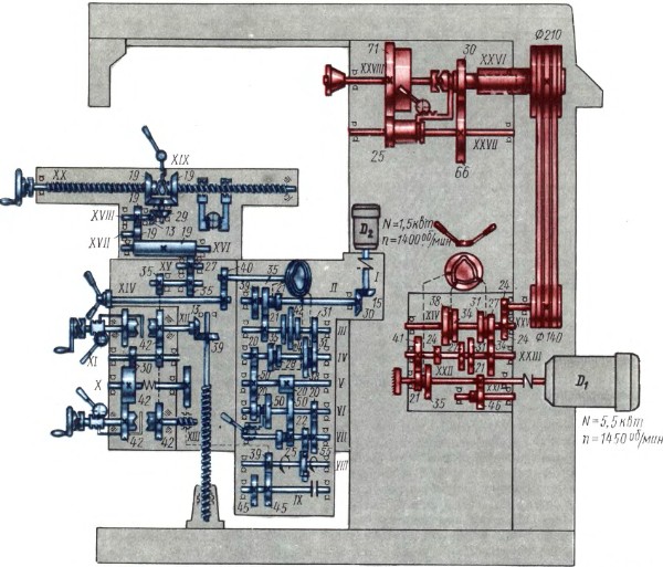
Rice. 115. Kinematic diagram of console milling machines models 6P81 and 6P81G
Chain of the main movement. From a 5.5 kW electric motor with a speed of 1450 rpm, the movement is transmitted through a semi-rigid coupling (shaft XXII) to shaft XXIII by means of two options transmissions: 35:27 or 21:41. In the future, always the number of the gear on the kinematic diagram means the number of its teeth. Thus, shaft XXIII can receive two different speeds.
It should be noted that with a constant modulus, theoretically, the condition for the cohesion of gears is that the sum of the numbers of teeth of the coupled pairs of wheels must be constant.
For greater clarity and clarity, we will analyze the kinematic chain of the main movement simultaneously according to the kinematic scheme (Fig. 115) and according to the so-called structural diagram (grid) of the spindle speed (Fig. 116). Shown in fig. 116 the grid of revolution numbers gives a visual representation not only of all the revolutions per minute of all the shafts of the mechanism, but also of the gears through which each of these numbers is obtained. On the diagram, 7 vertical lines are drawn at an equal distance from each other in accordance with the number of gearbox rollers (shafts XXII-XXVII, see Fig. 116), as well as horizontal lines. The distances between vertical and horizontal lines depend on the selected scale.
![]()
Rice. 116. Graph of the number of revolutions of machine tools of models 6P81, 6P81G and 6P11
Intersection points of vertical and horizontal lines vertically correspond to the number of revolutions (on any of the intermediate shafts) indicated by the numerical value on the spindle (shaft XXVIII). From shaft XXIII to shaft XXIV, the movement is transmitted through one of four pairs of gears: 34:27, 31:31, 27:34 or 24:38 (see Fig. 115 and Fig. 116). Here, the adhesion condition (11) is also satisfied with an accuracy of one: for all four pairs, the sum of the numbers of gear teeth is 61 or 62, respectively (with a constant modulus m - 2.5 mm).
It is easy to see that if from a shaft with n different speeds the movement is transmitted to the next shaft in m variants (m = 2, 3, 4, etc.), then the number of different speeds of this shaft will be equal to the product mn, i.e. it doubles, triples, etc. So, in our case, the shaft XXIII has two speeds and the movement to the shaft XXIV is transmitted by four various options. Therefore, shaft XXIV has eight (2 4) different speeds (see figs. 115 and 116).
The numerical values of the revolutions can be determined with sufficient accuracy and according to the graph (see Fig. 116). From shaft XXIV to shaft XXV, the movement is transmitted through gear wheels 24:24. From shaft XXV to shaft XXVI, the movement is transmitted by means of a V-belt transmission with a gear ratio of 2:3. When the clutch connecting the shaft XXVI with the spindle (shaft XXVIII) is engaged, it is possible to transmit highest values spindle speed (1600, 1250,1000,800, 630, 500, 400, 315 rpm). The movement from shaft XXVI to the spindle can be transmitted using enumeration, from shaft XXVI to shaft XXVII using gear 30:66 and from shaft XVII to shaft XVIII (spindle) by gear 25:71. The overdrive gear ratio is approximately 1/6, i.e. overdrive works like a downshift. Thus, the spindle has eight highest speeds when working without enumeration and eight smallest numbers revolutions (250, 200, 160, 125, 100, 80, 63 and 50 rpm), i.e. only sixteen various numbers revolutions.
Directly from the kinematic diagram or from the structural diagram, you can write the equations of kinematic chains to determine all sixteen steps of the spindle speed. To determine the maximum number of revolutions of the spindle, it is necessary to select the gears with the largest gear ratio from various gear options from one shaft to another, and to determine the minimum number of revolutions - with the smallest one.
Change the direction of rotation of the spindle by reversing the motor.
Feed chain. The feed mechanisms are driven by a 1.5 kW flange electric motor directly connected to shaft I by a semi-rigid coupling. The feed box consists of 9 shafts (I-IX). On fig. 117 shows a graph of the feed box drive. According to the structural grid (Fig. 117) and the kinematic diagram (see Fig. 115), it is easy to see that the machine can obtain a number of feeds along a geometric series with a denominator (φ \u003d 1.26 in the range of 25-800 mm / min for the longitudinal crossbar feeds and in the range of 8.3 - 266.7 mm / min for vertical feeds.
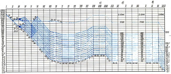
Rice. 117.
The equation of the kinematic chain for the largest longitudinal feed (see Fig. 115 and 117),
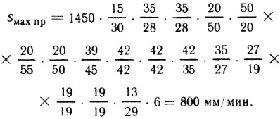
Also, according to the feed box drive schedule, you can easily write all other equations of kinematic chains for longitudinal, transverse and vertical feeds.
The working movement from the feed box is transmitted to the reverse box by means of an overrunning clutch of the working stroke. The reverse box is used to convert the torques taken from the output shaft of the feed box into the corresponding working movement (longitudinal, transverse and vertical) in two mutually opposite directions. On the input shaft X, a ball safety clutch is installed, adjusted to transmit the maximum torque. Shaft XIII is a cross feed screw. At the ends of the shafts XII and XIII there is a handle and a handwheel for manual movement in the transverse and vertical directions.
Rapid table, cross slide and console movements. These movements are carried out along the kinematic chains shown in Fig. 117 dotted line. Rapid traverse for longitudinal and transverse feeds is 3150 mm/min, and for vertical one three times less - 1050 mm/min.
Console milling machines No. 2 with a table width of 320 mm and No. 3 with a table width of 400 mm
These machines are manufactured at the Gorky Plant of Milling Machines (GZFS). The plant produces machines of the following models: 6R82G and 6R83G - horizontal milling machines; 6P82 and 6P83 - universal milling; 6P12 and 6P13 - vertical milling; 6R12B and 6R13B - vertical milling, high-speed; 6R82Sh and 6R83Sh - wide universal.
Console milling machines of the "P" series are more advanced models compared to the previously produced machines of the "M" series. New models have high rigidity and vibration resistance, which in turn increases the durability of the cutting tool and labor productivity. The design of the quill clamp has been redesigned and provides secure fastening and protects the quill from axial movement, ensuring a stable position of the spindle axis. The reliability of the electrical equipment of machine tools has been increased by placing the equipment in isolated electronic niches and improving the wiring of electric drives in the machine. In new models, the lubrication of the console guides and the “table-sled” unit is carried out centrally from the plunger pump. Thanks to effective lubrication, the durability of these components is increased, the original accuracy of the machine is maintained longer and the time for its maintenance is reduced. Ball bearings are used in the lead screw bearings instead of quickly wearing cast-iron bushings, bearing lubrication has been improved. A protective shield has been introduced at the end of the table to protect the table guides from chips when the table is moved to the leftmost position.
Technological capabilities of the machines of the "P" series have been expanded by increasing the longitudinal travel of the table by 100 mm. For a more accurate setting of the table in a given position, a new fastening of the limbs is used. Machines of the "P" series have perfect forms that meet modern requirements of technical aesthetics.
The main components of these machine models are unified.
For ease of management and reduction of auxiliary time costs, in addition to automation of the processing cycle on machines of the "M" and "R" series of the Gorky Plant of Milling Machines, it is provided: duplicated (in front and on the left side of the machine) change in the number of revolutions of the spindle and table feeds by single-handle and selective mechanisms that allow set the required number of revolutions or feed by turning the dial without passing through intermediate steps; control automatic movements table from the handles, the direction of rotation of which coincides with the direction of movement of the table; start, stop the spindle and turn on fast movements using the buttons; spindle braking by direct current; the presence of fast movements of the table in the longitudinal, transverse and vertical directions.
Kinematic scheme of machines
On fig. 118 shows a kinematic diagram, and in fig. 119 is a graph of the number of revolutions of the spindle, explaining the structure of the mechanism of the main movement of console milling machines 6P12 and 6P13.

Rice. 118. Kinematic diagram of machine tools models 6P12 and 6P13

Rice. 119. Graph of the number of revolutions of machine tools 6P12 and 6P13
The gearbox of machines 6R82G, 6R82, 6R83G and 6R83 differs only in the horizontal arrangement of the spindle, and the feed box is the same with machines 6R12 and 6R13. The gearbox of the horizontal spindle of the universal cantilever milling machines 6P82Sh and 6P83Sh, as well as their feed box, are completely unified.
Chain of the main movement machines 6P12 and 6P13. From an electric motor with a power of 7.5 kW for a 6P12 machine and (10 kW for a 6P13 machine) through an elastic coupling, the movement is transmitted to shaft F, and from shaft I to shaft II through a gear train 27:53. On shaft II there is a triple block of gears, with which it is possible to transmit rotation to shaft III with three different speeds through gears 22:32, 16:38 and 19:35. From shaft III to shaft IV, movement can also be transmitted in three different gear options: 38:26, 27:37, 17:46. Therefore, shaft IV has nine different numbers of revolutions (3x3 = 9). The V shaft receives its drive from the IV shaft through a double gear set using 82:38 and 19:69 gears. So the V shaft has 18 different speeds (9x2=18). From shaft V, the movement is transmitted to shaft VI by a bevel gear 30:30, and from shaft VI to spindle VII - through a gear 54:54. According to the graph (see Fig. 119), you can write the kinematic chain equation for any of the 18 speeds. So, for example, for largest number spindle speed it will look like this:
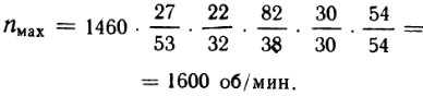
Feed chains. The feed drive is carried out from a separate flange motor with a power of 2.2 kW for the 6P12 machine and 3 kW for the 6P13 machine. According to the kinematic diagram of the machines (see Fig. 118) and the feed schedule (Fig. 120), we will analyze the kinematic feed chains.
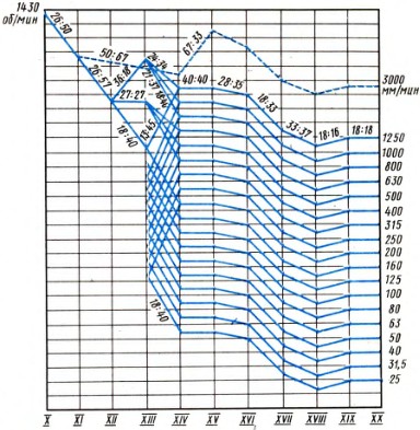
Rice. 120. Graph of the drive of longitudinal feeds of machine tools of models 6P12 and 6P13
Through gear 26:50 shaft XI receives rotation, then through gear 26:57 - shaft XII. On the shaft XII there is a triple movable block of gears, which informs the shaft XIII of three speeds of rotation through gears: 36:18, 27:27 and 18:36. On the XIV shaft there is a triple movable block, with the help of which the movement from the XIII shaft to the XIV shaft can also be transmitted in three gear options 24:34, 21:37 and 18:40. Therefore, shaft XIV has nine different numbers of revolutions (3 x 3 = 9). When the movable gear wheel 40 with cams at the end is moved to the right and is engaged with the clutch M 1 rigidly connected to the shaft XIV, the rotation from the shaft XIV to the shaft XV is transmitted directly. If the gear wheel 40 is engaged with the gear wheel 18 (as shown in the diagram), thereby turning on the clutch M 1, then the movement on the shaft XIV will be transmitted through the relay. Bust here works like a downshift. Thus, the feed box of console milling machines 6R82G, 6R82, 6R12, 6R12B, 6R13, 6R13B, 6R82Sh and 6R83Sh has 18 different feeds: nine when working without enumeration and nine when working with enumeration. From shaft XIV to shaft XV, the movement is transmitted through a 40:40 gear. From the wide gear wheel 40, mounted on the shaft XV, the safety clutch M p with the cam clutch M 2 turned on, the movement is transmitted to the shaft XV, and from it to the shaft XVI by means of a gear 28:35. From shaft XVI to shaft XVII, the movement is transmitted through gear 18:33. From the shaft XVII, it is possible to transfer all the speeds to the lead screws of the longitudinal, transverse and vertical feeds. So, the longitudinal feed is then carried out according to the following chain: from the shaft XVII to the shaft XVIII with a gear of 33:37, from the shaft XVIII to the shaft XIX - through a pair of bevel gears 18:16, and from the shaft XIX to the shaft XX - the lead screw of the longitudinal feed is also through a pair of 18:18 bevel gears.
Fast movements of the table in all directions are carried out with the friction clutch M 3 on and are carried out along the kinematic chain shown in fig. 120 dotted line. As can be seen from fig. 118, rotation from the feed motor is transmitted to the XV shaft through gears 26:50, 50:67 and 67:33 and further along the kinematic chains of working feeds.
Setting up machines for automatic work cycles
For console milling machines of the "M" and "P" series, the longitudinal movement of the table can be controlled by semi-automatic or automatic cycles. In the conditions of single production, the control of the longitudinal feed and the rapid movement of the table is carried out manually. In serial production, these machines can be configured for semi-automatic (jumping) and automatic (pendulum) processing cycles. For this purpose, in the side T-slot of the table, cams are installed in a certain sequence and at a certain distance from each other (see Fig. 39), which at the right moments act on the sprocket for controlling the fast and working movements of the table and on the longitudinal feed switching handle, ensuring the operation of the machine according to a given cycle.
The table can be configured for the following automatic cycles:
- semi-automatic intermittent: a) quickly to the right - feed to the right - quickly back (to the left) - stop, etc. (Fig. 121); b) quickly to the left - feed to the left - quickly back (to the right) - stop, etc. (Fig. 122), i.e., the same cycle of table movements is obtained, but only to the left side;
- automatic pendulum cycle: fast right - feed right - fast left - feed left - fast right, etc. (Fig. 123).
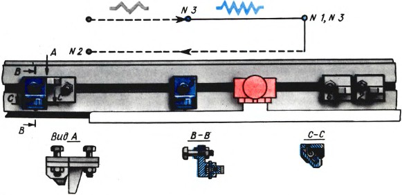
Rice. 121. Setting the cams with a one-sided semi-automatic cycle to the right

Rice. 122. Setting the cams with a one-sided semi-automatic cycle to the left
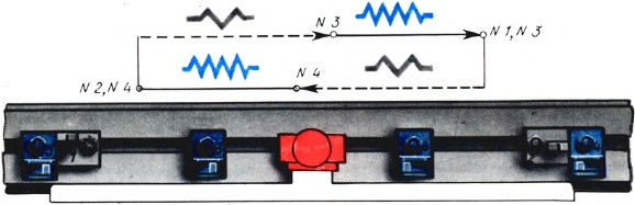
Rice. 123. Setting the cams with a pendulum cycle
To set up the machine for automatic operation, necessary:
- disconnect the machine from the network with the input switch "on - off";
- put switches for manual or automatic control of the longitudinal movement of the table and work round table to the "Automatic control" position;
- turn on the machine with the input switch "On - Off":
- install the cams depending on the adopted cycle.
When setting for automatic operation, it must be borne in mind that switching from feed to fast travel or from fast travel to feed is possible at any point in the stroke and in any direction of movement and is limited only by the possibility of setting the cams at this point.
The switch for manual or automatic longitudinal movement of the table is set in the neutral position, the handles of the longitudinal stroke by pressing it with a screwdriver until it stops and turning it to the fixed position "Automatic control".
Stopping the movement of the table to the right or left is made by cams No. 5 or 6, which act on the protrusions of the longitudinal stroke handle. Jaws no. 1 and 2 should never be removed from the machine as they limit extreme positions table.
Switching from feed to high speed or from high speed to feed (when the table moves to the right or left) is made by cams No. 3 and 4, which act on the sprocket.
The right and left cams differ only in the position of the lever. If necessary, the lever can be moved to the other side.
When working with manual control, cams No. 3 and 4 are recommended to be removed or rearranged to the non-working part of the table in order to protect the mechanism from unnecessary wear.
When milling a set of blanks at the same time, in which the surfaces to be machined are located at considerable distances from each other, the machine can be configured to work on a jump cycle of right or left feed.
In accordance with the location of the surfaces to be machined, the machine table will receive either fast or slow movements according to the scheme: fast to the right (or left) - feed to the right (or left) - fast to the right (or left), etc. - fast back - stop.
At automatic pendulum cycle workpieces to be processed are installed alternately on right side table, then on the left. During the processing of a workpiece installed on one side of the table, on the other side of it, the worker removes the processed part and sets new blank. The machine table in this case continuously performs a closed cycle of movements: fast to the right - feed to the right - fast to the left - feed to the left - fast to the right, etc.
When the table is operating in an automatic cycle, it is necessary to keep in mind the following: the cycle is switched on when the spindle is turned on with the longitudinal stroke handle in the direction of the workpiece supply; setting the handle to the "Stop" (neutral) position allows you to turn on the feed or rapid traverse in all cases, regardless of the machine setting for automatic cycle or manual control, with the exception of the moment the sprocket is turned by the cam. At this point, the table can only be stopped using the Stop buttons. Before switching on the table after such a stop, it is necessary to check whether the sprocket is fixed.
In the conditions of an automatic cycle, the "Quick table" buttons do not work.
Console milling machines No. 4 with a table width of 500 mm
The Ulyanovsk plant of heavy machine tools produces console milling machines: a horizontal milling machine model 6N84G and a vertical milling machine model 6N14. The machines have a stepless feed drive in the longitudinal, transverse and vertical directions from the electric motor direct current with magnetic amplifiers. Machines can be configured for automatic and semi-automatic work cycles.
We also recommend
 Switching power supply: repair and refinement
 Remote control of light
 Swimming lessons for preschool children
 Notes for the master - home household alarms
 Clock propeller on Atmega8
 Device and relay application examples, how to choose and connect a relay correctly Microcontroller and relay simple switching circuits