Horizontal milling machines for metal. Horizontal milling machines and machining centers
The Swiss manufacturing and engineering company ENCE GmbH (ЭНЦЕ ГмбХ) was founded in 1999, has 16 representative offices and offices in the CIS countries, offers equipment and components from production sites in Turkey and the Republic of Korea, is ready to develop and supply according to your individual terms of reference milling machines.
Milling process
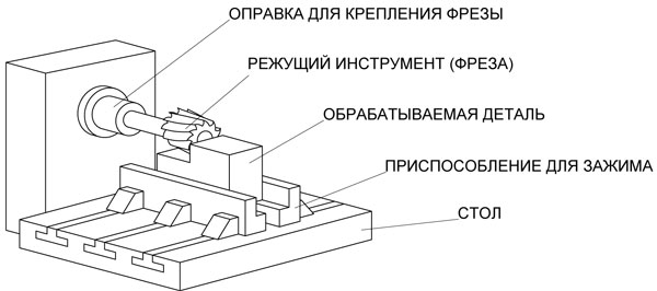
Milling is technological operation associated with surface treatment with milling cutters.
During the milling process, the cutter rotates mainly, and the feed goes in a rectilinear and perpendicular direction with respect to the cutter, i.e. to its axis. On the table of the milling machine, the workpiece is fixed with a vise.
The function of a milling cutter is different from that of multi-blade tools found on drill presses.
Due to the perpendicular feed relative to the axis of rotation of the cutter, each of its teeth touches the workpiece, but makes only a small part of its revolution. Several cutter teeth work at the same time, although only one tooth can work. The cutter has many teeth, each of which is in operation for a short period of time. During the main part of the rotation, the cutter is cooled, which, in turn, guarantees a long service life of the cutter itself and the efficiency of the milling process.
The geometric structure of each cutting tooth of the cutter is similar to the type of cutter. The milling process, however, has its own specific feature: the nature of the contact of the teeth of the cutter with the surface of the part is intermittent, which favorably affects the process in terms of reducing the effect of the heat released during milling on cutting edge tool and causes not such a calm and smooth process, as in turning.
According to the shape of their tooth, cutters are divided into:
- cutters equipped with pointed teeth;
- milling cutters with sharpened teeth.
For milling cutters of the first type, the cutting profile of the teeth consists of straight lines, the teeth are sharpened along the back edge, and the backed teeth of the cutters are sharpened, on the contrary, along the front edge. When regrinding, the tooth profile of a backed cutter is maintained, which is a big advantage over pointed cutters, which are used for milling at high speeds and are therefore made of carbide.
Cylindrical milling cutters are also used for surface treatment by milling, when the machine table moves towards the cutter (upstream milling) or moves in the same direction as the cutter (climb milling). Chips in the form of a comma are removed with these methods by each tooth of the cutter. With up milling, the chip thickness gradually increases, while with down milling, on the contrary, it decreases during cutting. Up milling contributes to a gradual increase in the load on the tooth, which is an advantage, and the disadvantage of this method is the attempt of the cutter to tear the part off the table surface. Climb milling does everything the other way around, so the choice of method is determined by the specific working conditions.
Milling cutting data
cutting speed is the peripheral speed of rotation of the cutter.
V = πD n/1000, m/min,
where D - cutter Ø, mm,
Innings- movement of the workpiece along the axis of the cutter per unit of time.
S m = S z z n, mm/min,
where z is the number of cutter teeth,
n - number of revolutions made by the cutter / min
Depth of cut- a layer of metal that removes cutters in one pass;
Milling width- the length of the surface in contact with the cutter in the direction perpendicular to the feed direction.
Chip thickness- the value removed by each cutter tooth.
Cutting forces and milling power
In the process of cutting, a certain force acts on each tooth of the cutter, the directions and magnitudes of which differ, depending on the nature of the milling and the direction of feed. When milling the ends with a cutter, with a counter feed, the cutting force P acting on the tooth of the cutter can be divided into two component quantities: tangential P z and radial P y . According to the radial force P y, the mandrel on which the cutter is seated is calculated for bending. The total value of P z is defined as the sum of the forces acting on the teeth:
P z sum \u003d P z 1 + P z 2 + P z 3 kg
Milling torque:
M \u003d P z D / 2 kg mm,
where D - cutter Ø,
Milling power:
N = M n / 974000 kW,
where M is torque,
n is the number of revolutions made by the cutter in 1 min.
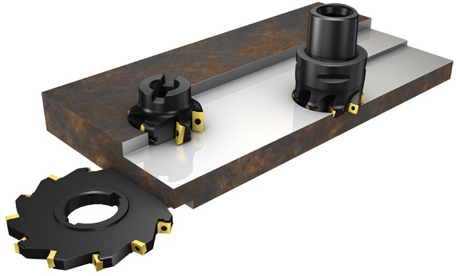
Main types of cutters
A milling cutter is a milling machine tool designed for cutting and having several teeth. The tooth is nothing more than a chip cutter.
Cutting in a milling operation differs, however, from cutting processes in grinder or drilling. At the cutter, as we mentioned above, the teeth during cutting are not all involved in the work, but alternately. The service life of the cutter is thereby increased and the efficiency of the milling process is increased.
The figure below shows a variety of cutters that differ in different features and features:
- for their application,
- according to the shape of the teeth
- in the direction of the teeth
- according to their execution
- by the type of their fastening on a milling machine, etc.
According to the design, the cutters can be:
- whole,
- soldered,
- typesetting,
- milling heads based on replaceable teeth.
1. Solid cutters, these are positions 1, 2, 4 and 7 in the figure. They are a single piece of high quality material intended for the manufacture of milling cutters and other cutting equipment.
2. Common inexpensive structural steel is used for brazed cutters. A piece or plate of high-quality metal is soldered onto the upper part of the tooth or cutter.
3. Type-setting cutter, this is position 3 in our figure. It is a round body made of alloyed structural steel, where the teeth are inserted and fixed with a wedge or a conical pin. For sharpening, the type-setting cutter is not disassembled, but processed in the assembled state.
4. Milling heads, in our figure this is position 15. The head is equipped with quick-change teeth, conventional cutters. For sharpening, the milling head can not be disassembled, but processed in the assembled state, or you can sharpen the teeth individually, and then attach them to the body.
According to the type of fastening, cutters are distinguished:
- mounted
- tail
- end
Shell mills, positions 1, 3, 4 and 7 in our figure, are cutters with a hole and a keyway, they are mounted directly on the spindle arbor.
The tail cutters, positions 6 and 9, are a continuation of the tail (conical or cylindrical) and, together with the tail, are an integral part.
Face mills, position 15, are mounted on the end of the shaft with bolts.
According to the scope of the cutter, they are divided into the following main types:
- for plane processing,
- slotted (pos.5),
- grooved (positions 4, 9 and 6),
- corner (positions 7 and 8),
- shaped (position 10),
- for cutting teeth (positions 11, 12 and 16),
- for threading (positions 14 and 13) and
- special.
Basic operations performed by milling using various cutters
The figure below shows a number of operations carried out using various types of cutters in the milling process.
Cylindrical and face mills, positions 1 and 2 in Figure 3, are used for processing planes. The purpose of the disk, end, groove and corner cutters, position 3 in the figure, is to create grooves and grooves on the workpiece. Position 4 displays shaped cutters used for processing shaped surfaces. Disc and finger cutters in the form of modules, positions 5 and 6, cut teeth on gear wheels.

Milling machines
The main types of milling machines:
1) machine tools general purpose: horizontal milling, universal milling and vertical milling.
2) machines for a specific purpose and specialized.
Horizontal milling machines are equipped with a bed along which a console with guides moves in the vertical direction, along which, in turn, a cross slide runs parallel to the spindle axis. The table with the gearbox and the feed box moves in the direction perpendicular to the spindle axis.
Milling cutters are attached to the mandrel. End mills are inserted into the spindle and centered with a conical socket.
The table of a universal milling machine, unlike a horizontal milling machine, can be turned in a horizontal plane by 45 degrees. So the feed direction of the table can change in relation to the spindle axis from 45 to 90 degrees, which is required when milling spirals.
Vertical milling machines have a vertical spindle, otherwise they are the same as horizontal milling machines.
Tables of longitudinal milling machines can only move in a horizontal plane located perpendicular to the axes of vertical or horizontal spindles, the presence of which allows processing parts from several sides at the same time. Parts are processed by cutters in contact with spindles. The table does not extend or move in the transverse direction, and tools are installed by extending the spindles along their axis and moving the headstocks along the guides.
Carousel-milling machines used for continuous processing of flat surfaces have round tables of large diameters, parts are removed when the table continues to rotate.
The purpose of drum milling machines is the same as that of rotary milling machines. The difference is that on the drum milling machines parallel planes are processed simultaneously from two sides. Inside the frame of these machines, a drum rotates, on which the parts to be processed are placed and the finished ones are removed. The cutters are in the headstocks, each pair of cutters performs sequentially first rough, then fine milling. These machines have good rigidity and high productivity.
Specialized milling machines process mainly large parts in mass production.
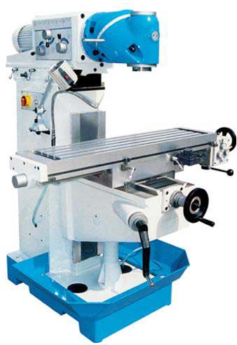
Description and principle of operation of milling machines
One of the types of universal tools is a milling machine. It is a machine tool with a cutting tool called a milling cutter with many blades. The main movement of the cutter is its rotation. The cutter is mounted on a vertical shaft. But the shaft can also be installed in a different way so that it looks at the workpiece at an angle. The machine table can be moved manually or by means of a drive, however, a mechanical one. At the same time, control is carried out quite accurately on scales that have an optical zoom system.
The shaft of the milling machine, or, as it is commonly called, the spindle on which the cutter is mounted, is horizontal. The part to be processed is fixed on the table. The table, in turn, is the simplest, with movement along 3 axes. There are also universal tables. These have the ability to turn around at an angle.
Modern engineering makes it possible to process parts with a complex profile surface: these can be the surfaces of dies, molds, where shaping is important, etc.
To obtain parts with such surfaces, such types of processing as casting, stamping, cutting are used. But only cutting makes it possible to obtain surface parameters that are close to the specified values (setpoints), and reduce the time for subsequent processing. Often milling is the only possible method to perform this type of processing, since so many machine-building factories and plants have switched to mass and small-scale production. And in productions of this kind, it is considered cost-effective to process parts by milling.
The process of technological treatment of surfaces with a complex profile is based on the following operations:
1) harvesting, 2) milling, 3) finishing.
The finishing procedure is carried out manually. The complexity of this operation and the labor costs for it are determined by the final surface parameters that take place after milling. If a high roughness class is ensured at the stage of milling, then it is possible to reduce the time spent on finishing. For finishing is the most time-consuming stage in the process of technological processing.
Classification and purpose of milling machines
Surfaces can be processed on milling machines various forms. These are both external and internal planes. You can process:
- grooves;
- planes;
- grooves;
- linear shaped surfaces.
For processing the latter, special types of milling machines are used, because this is work with complex spatial planes. Behind lathes milling machines are in one of the leading positions in their prevalence, as they are highly productive and quite versatile.
Types of milling machines:
- console- milling machines;
- consoleless milling;
- longitudinal milling;
- copy-milling.
They can be vertical, horizontal, universal and highly versatile. This machine is very popular. Equipping with a console distinguishes it from other types of machines. The console, rigidly fixed on the body of the machine itself, moves along the guides on the frame, and the slide located on top moves the console in the transverse direction. In contrast to the spindle, which practically does not move, on this type machine table moves. The workpiece is fixed on it, together with which it moves in space, making both perpendicular movements and movements at an angle relative to the spindle axis.
Processing on milling machines. Types of milling
Milling processing is associated with the performance of operations on parts of various planes and surfaces on milling machines. These are operations directly related to:
- plane processing;
- shaped surfaces;
- cutting grooves;
- thread cutting;
- cutting teeth on gear wheels;
- by simply cutting a piece of metal.
Universal milling machine
On a universal milling machine, flat and shaped surfaces (external and internal), grooves, ledges, rotation bodies, holes, threaded connections, gear teeth. This type of machine is widely used in repair departments, locksmiths, carpentry shops and workshops, equipped with a digital measurement device in three axes: vertical console feed in fast mode, table feed in both directions in fast mode. There is a working lighting and cooling system in the machine.
Operations performed: procedures for drilling, milling, threading, etc.
CNC Horizontal Milling Machining Center
The horizontal CNC milling machining center belongs to the heavy series of this type of design and is designed for the following types of machining: roughing, semi-finishing and final finishing. Working in difficult functional conditions of the processing of large-sized body parts with complex design made of cast iron, structural steel, stainless steel, heat-resistant steel and alloys, this center guarantees high rigidity and resistance to vibrations. The hydrodynamic guides of the machine guarantee the safety of the precision parameters, as well as the ability to cut difficult-to-cut materials.
Machining table dimensions: 630x630 mm;
Movements in X/Y/Z axes: 900/800/710 mm;
Spindle speed: 4500 rpm. (910 Nm - 1080 Nm);
Number of tools: 60;
CNC system;
Basic equipment for CNC horizontal milling machining center
- CNC system with color graphic screen;
- Rotary table;
- Tool shop;
- Spindle cooling system;
- Coolant supply system;
- A casing that completely covers the working area of the machine;
- Remote Control;
- Maintenance tool kit;
- Belt conveyor with trolley (for chip removal);
- Lighting lamp working area;
- Automatic shutdown nutrition;
- Sump;
- Electric cabinet cooling system;
- Instructions for use and repair of the machine
Work carried out on milling machines
The scope of work that can be performed on milling machines is very diverse and large. These are procedures for processing planes, milling grooves and grooves, milling shaped surfaces, milling surfaces of revolution, cutting gear teeth, etc.
Types of work on milling machines and tools used:
- Surface machining with a cylindrical cutter with a spiral tooth
- Machining a plane with an end mill with inserted teeth
- Side cutting with disc cutter
- Machining both sides of an open slot with a double-sided disc cutter
- Milling a groove with a three-sided disc cutter
- Milling two sides of an open slot with an end mill
- Milling a groove with an end mill
- Milling the sides of a protrusion with a set of two disc double-sided cutters
- Milling a semi-circular groove with a shaped semi-circular cutter
- Milling a complex profile with a prefabricated set of cutters of various types.
Tooling for milling machines
Among the fixtures available for milling machines, there are universal, normalized and special. They are subdivided, in turn, into single and multi-place, among which there are fixed, movable and rotary, for continuous milling.
Dividing heads known to all of us, machine vices, rotary tables, corner tables, rotary tables are universal milling fixtures.
Machine vices are usually equipped with a conventional manual screw clamp (eccentric or pneumatic) for mounting parts on them.
The most commonly used pneumatic vise with a rubber diaphragm. The workpiece is clamped between the jaws. With the entry of air into the vise chamber, the diaphragm moves along with the disk and the rod, and the rod turns the crank lever, and the workpiece is fixed with a force of 900 kg at an air pressure of 4 atm.
Dividing heads change the angle of the part relative to the cutter and are divided into simple, universal and optical. There are three methods of dividing with dividing heads: direct, simple and differential. The direct method simply involves turning the head (dividing) spindle through a predetermined angle. Simple and universal heads are suitable for this purpose.
The areas of use for universal dividing heads are very diverse:
- for periodic rotation of the workpiece by certain given angles
- for continuous rotation of the workpiece when milling spirals
- to give the workpiece a given angular position relative to the plane of the table on the machine
If it is necessary to observe the exact rotation of the workpiece to the desired angle (permissible error max. 0.25 '), optical dividing heads equipped with a dial are used. The limb scale is observed through the eyepiece of the optical system inside the dividing head.
If it is necessary to rotate the workpiece in a horizontal plane, the use of a rotating universal tables. Such tables are set in motion manually or mechanically.
To position the part in relation to the plane of the milling machine table itself at a certain angle, give priority to the corner tables.
Rotary tables are chosen for positional processing.
Console milling machine
- base in the form of a box, where the gearbox and gearbox control unit are located;
- spindle assembly;
- trunk;
- suspension;
- spindle milling mandrels;
- console;
- sled;
- a table where the part is placed for processing;
- base plate.
Consoleless milling machines subdivided:
- for vertical and
- horizontal.
Consoleless milling machines vertical type are used to carry out operations on parts of a rather large size. Milling is performed at high speed with an automatic control cycle. The automatic cycle carries out:
- work flow,
- reverse at high speed and
- stop.
On modern consoleless milling machines, the cutter is automatically retracted from the surface of the part in order to protect it. The milling process is carried out on these machines at high speed, which is their great value. The machine processes body parts with a large machining allowance. Table vertical movement does not have, only transverse and longitudinal movement. The spindle head moves vertically. The spindle itself stands upright and has big number revolutions, up to 1250 rpm, so that milling takes place at a very high speed.
CNC milling machine
CNC milling machines are machines with an automatic control system. Automation moves the table and controls the spindle speed. Sometimes the spindle is placed on a carriage or slide, which contributes to its movement in the direction along the axis and vertically. On this type of CNC machine, parts are serially machined with high-precision surface treatment in three-dimensional space. For example, parts for aviation or energy industry like airplane and helicopter propeller blades, turbine blades and large industrial fans.
Speaking of copy-milling machines, the idea immediately arises of copying, creating a copy or reproducing something, repeating a carbon copy. Therefore, copy-milling machines create a non-flat surface on the part, while processing the curved surfaces of dies, punches, which are subsequently used for stamping parts from sheet steel. At the same time, the resulting form, as it were, copied the given sample, becoming similar to it. When processing, the cutter shifts the profile of the copier to the workpiece.
If an automatic cutter changer is installed on a CNC milling machine, the machine will perform the functions of a machining center, while doing many processing actions in automatic mode.
Numeric program control contributes to the implementation of the most complex technological actions for processing parts in automatic mode. Operator actions are not necessary during operation. The control system is loaded with programs for various processing steps. The processing program is selected before the start of the process. The choice of the program is carried out by the operator from the control post. From the same post, you can control the machine in manual mode and turn off the machine in case of an emergency. The visual system displays all the actions performed by the machine, the operator monitors the execution of operations on the display screen.
On a CNC milling machine, parts made of cast iron, steel, as well as light metal alloys are processed. On this equipment, body parts are processed with a full range of operations in 3 coordinates (X, Y, Z) in the basic version of the machine and in four or five coordinates - in the optional version of the CNC machine, developed in the light of the latest world technologies necessary for small-scale and single productions.
The proposed machines are equipped with a CNC system, a graphic screen, which guarantees high-precision execution of commands. Servo drives equipped with digital control guarantee accurate and fast movement along three axes.
Optimal specifications machine allows you to carry out many operations with one setting: milling, boring, drilling, threading. Table and caliper hardware made of special high-strength cast iron, with high rigidity and vibration resistance, as well as design a powerful spindle and an automated system for supplying coolant to the cutting zone contribute to the growth of the high popularity of the machine.
Basic equipment of a CNC milling machine:
- Siemens CNC system;
- Protective cover;
- Automated system cooling;
- Oil and coolant separator;
- Automated lubrication system;
- Mounting bolts for installation on the foundation;
- Electric cabinet heat exchanger;
- Signaling;
- Documentation in Russian.
CNC milling machines are equipment that corresponds to a high level of modern man-made solutions, with the help of which precision parts are achieved with high fruitful returns.
Vertical milling machine. Description.
Vertical type milling machine can perform many milling operations various types cutters
The purpose of vertical milling machines is drilling, reaming and boring holes, processing horizontal and vertical planes, cutting grooves, frames, corners, cutting gear teeth, etc.
The machine can work with steel, cast iron surfaces, also process parts made of alloys, non-ferrous metals, plastics, etc. During processing, the cutter begins to rotate with the spindle, making rotational movements. The workpiece being processed is also in motion. Is it straight or curvilinear motion and is called milling. The part or workpiece is attached to the machine with tacks, a machine vice.
In a vertical console milling machine, the spindle is mounted vertically.
Vertical milling machines of the consoleless type process vertical inclined surfaces. The bed is installed directly on the foundation. On the guides of the bed, the slide and the table are moved. This version of the machine provides it with high rigidity, rigidity ensures the accuracy of processing and the ability to work with overall workpieces.
milling machines vertical design easy to use, due to the quick change of tools and fixtures.
Horizontally milling machine. Description
Unlike vertical milling machines, machines horizontal type spindle is horizontal. Almost all types of cutters can be used on horizontal milling machines.
To install the cutter, a mandrel with a length that is proportional to the width of the desktop is used.
All feeds in horizontal milling machines are carried out by means of table movement. Table movement control can be either manual or mechanized. The part to be processed is fixed in the T-slots of the table. As a rule, the table moves in three directions. But in some cases, the vertical movement is provided not by the movement of the table, but by the movement of the milling head.
On some horizontal type milling machines there is a table with a rotary device, which provides a rotation of ±45 ° horizontally. This has the advantage that the workpiece can be fed at an angle to the axis of the shaft (spindle).
Vertical-horizontal milling machine. Description
milling machines of the above type are designed for processing vertical, horizontal, inclined surfaces, grooves in parts large sizes. As a rule, their body is made of cast iron and is a cast structure. The advantages of such a rigid design:
- dampens vibrations well
- provides excellent roughness parameters during processing.
Like the consoleless type milling machines, these machines also do not have a console. The bed is installed directly on the foundation. On the guides of the bed, the slide and the table are moved. This version of the machine also provides it with high rigidity, rigidity ensures the accuracy of processing and the ability to work with overall workpieces and parts.
The vertical head of this vertical-horizontal milling machine has a rotation of ±45 degrees.
The control components are located on the local control panel. This provides additional convenience when operating the machine, being able to be near the machine at the time of control.
milling machines vertical-horizontal type belong to the wide-purpose range of milling machines.
Suggested milling machines
Milling machines series UNF 1
UNF1 series - stable design and high machining accuracy
Distinctive features:
- very large desktop
- universal milling head, can be installed at any spatial angle
Standard accessories:

| Specifications UNF 1 | ||
|---|---|---|
| Work zone | ||
| Mounting area of the table | 1120x260 | |
| T-shape grooves (number-width-distances) | 5-14-50 | 350 kg |
| Feeder | X travel | 600 mm |
| Y-axis travel | 300 mm | |
| Z travel | 440 mm | |
| X-axis travel speed | 24 - 720 mm/min | |
| X-axis rapid traverse | 1040 mm/min | |
| Vertical. milling head | ||
| Spindle taper | ISO 40 | |
| Spindle speed | 40–1600 rpm | |
| Console | 60–500 mm | |
| Distance from spindle nose to table | 0–440 mm | |
| Head swivel range | 360° | |
| Horizontal milling head | ||
| Spindle taper | ISO 40 | |
| Spindle speed | 40–1600 rpm | |
| Drive power | ||
| Main engine | 2.2 kW | |
| Dimensions L x W x H | 1655 x 1325 x 1730 mm | |
| The weight | 1360 kg | |
Milling machines series UNF 10, UNF 12B, UNF 15B
Distinctive features:
- Equipped with x, y, z servo
- Large working range
- Infinitely variable feed rate via servomotor and axial controller (English production) in all axes
- Fast access in all directions
- All gears are hardened, ground, nitrided and run through an oil bath as they rotate
- Simultaneous switching on of feed and clamping of the table is excluded
- Guide rails have Turcite-B coating
- Axles can be driven simultaneously
- There is a double number of all controls: to control the machine from the front side and from the left side
- Stable, skew-resistant guides of the upper arm (y-coordinate), square guides in x and z coordinates
- Universal milling head can be set to any spatial angle
- Automatic lubrication
- Wide range of accessories
- Tiltable control panel with all functional elements
- Spindle brake
Standard accessories:
- universal swivel head
- auxiliary tools
- centralized automatic lubrication system
- coolant dispenser
- protocol finished products according to DIN 8615
| Specifications | UNF 10 | UNF 12B | UNF 15B |
|---|---|---|---|
| Table top (L x W) | 1235 x 460 mm | 1635 x 500 mm | 2000 x 500 mm |
| Number of T-slots | 5 | 5 | 5 |
| T-slot size | 18 mm | 18 mm | 18 mm |
| T-slot width | 80 mm | 80 mm | 80 mm |
| Distance between T-slots | 900 mm | 1300 mm | 1500 mm |
| Longitudinal movement of the table along the X axis | 450 mm | 450 mm | 500 mm |
| Lateral Y-Axis Movement | 650 mm | 650 mm | 650 mm |
| Head Angle Range | 360° | 360° | 360° |
| Spindle clamp | ISO 40 | ISO 50 | ISO 50 |
| Spindle speed | (27) 30–2050 mm/min | (27) 30–2050 mm/min | (27) 30–2050 mm/min |
| Longitudinal feed (stepless) | 10–1000 mm/min | 10–1000 mm/min | 10–3000 mm/min |
| Transverse feed (stepless) | 10–1000 mm/min | 10–1000 mm/min | 10–3000 mm/min |
| Feed vertical (stepless) | 6–640 mm/min | 5–500 mm/min | 5–500 mm/min |
| High speed longitudinal | 2540 mm/min | 2200 mm/min | 2200 mm/min |
| Rapid traverse | 2540 mm/min | 2200 mm/min | 2200 mm/min |
| Fast move vertical. | 1700 mm/min | 1300 mm/min | 1100 mm/min |
| Distance spindle nose - table | 50 - 500 mm | 80 - 530 mm | 50 - 530 mm |
| Departure | 63 - 713 mm | 60 - 760 mm | 28 - 760 mm |
| Head power. engine | 5.5 kW | 7.5 kW | 7.5 kW |
| Axial drives | DC servo | DC servo | DC servo | 800 kg | 1800 kg | 1800 kg |
| Dimensions (LxWxH), mm | 1940x2200x2115 | 2140 x 2621 x 1940 | 2140 x 2986 x 1940 |
| The weight | 3000 kg | 3400 kg | 5500 kg |

| Characteristics | Suggested machine |
| Travel along the X axis, mm | 1400 |
| Y-axis travel, mm | 600 |
| Movement along ogh 2, mm | 600 |
| Table dimensions, mm | 1700 x410 |
| T-slots, mm | 4x 18 x 70 | 1200 |
| Axis travel, mm/min Rapid traverse mm/min |
X Y Z 10-3000 X Y Z 4800 |
| Spindle type | NT50 |
| Diameter, mm | 127,53 |
| Spindle speed, rpm | 60-3000 |
| Distance from spindle head to table surface, mm | 690 |
| Main drive power, kW | 10 |
| Machine weight, kg | 4300 |
The proposed machine has a lower power consumption, which does not affect productivity, due to higher processing speeds. The dimensions of the table allow you to unify the two types of machines included in the project into one.
Contents of delivery
Telescopic X-axis
Telescopic Y-Axis Broaching Machines
Horizontal milling machines differ in design, they can be single-column and double-column, console and without console. CNC machines, as a rule, have a rotary table, a certain trajectory of movement of which is set by the embedded program.
Horizontal milling machines - machines with a horizontal spindle, as well as having the ability to move the table in three mutually perpendicular directions.
The basis of the horizontal milling machine is the bed, on which all the nodes and mechanisms of the machine are located:
- gearbox;
- the console moved along the vertical guides of the bed;
- a table for installing a blank inserted into a special device or fixed in a vice installed on it. the features of the milling machine table are that its movement can occur in three directions
- longitudinal movement occurs along the guide rail;
- lateral movement is obtained by moving the sled itself along the console guides;
- The table receives vertical movement when the console moves along the frame guides.
- spindle - the main rotating part in the machine mechanism;
- a feed box located in the console;
- a trunk that serves to secure the suspension;
- the milling post is supported by the hanger end.
Universal machines are called horizontal milling machines with a rotary plate, thanks to which the desktop can turn from a horizontal surface into an inclined one. These machines can also be equipped with CNC, but this will not speed up, but rather slow down production due to the fact that reprogramming the machine will take a lot of time.
Layout of horizontal milling machines Kinematic diagram 6Р81 Device of a horizontal milling machine
Cylindrical cutters are used to process the horizontal plane of parts. Vertically, metal blanks are turned with face or disk cutters. If necessary, combined processing of the workpiece, several different milling cutters are used. The accuracy of the task is directly dependent on the stability of the cutters in the mount along the length of the shipment. Suspensions help to increase the rigidity of the mount. But not a single additional support will give sufficient stability to the cutter when its diameter increases beyond the standards specified by the machine manufacturer. The most accurate execution of the work will be if the machine is equipped with a CNC.
The rigidity of horizontal milling machines for metal increases with the improvement of the frame design, the installation of an additional bracket, and the strengthening of the table. Work performed on lathe for metal, can also be produced on horizontal milling equipment using special milling heads. Installing the CNC on the machine is always accompanied by strengthening the structure.
In the classification, horizontal milling machines are assigned to the sixth group, but some of them may also belong to the fifth as gear-cutting and thread-cutting equipment. CNC is more often installed on machines of the 6th group. Group 5 equipment is not designed to perform particularly precise tasks. CNC here can only be installed to speed up production, if necessary, process identical workpieces in in large numbers.
According to the classification table of turning equipment for metal, machines are divided by weight:
- Group 1 - light, weighing up to 1 ton;
- Group 2 - medium, whose weight does not exceed 10 tons,
- Group 3 - heavy. This group is divided.
- Large - from 10 to 30 tons;
- Heavy - from 30 to 100 tons;
- unique, over 100 tons in weight.
Any equipment for metal can be equipped with CNC.
The second criterion for the division of equipment is automatic, semi-automatic or manual control of the machine. With manual control, switching on, stopping, approaching a tool, adjusting feeds and speeds, installing parts and removing them from the working surface is carried out by a turner.

Semi-automatic is configured for a specific processing cycle. The worker needs to install the workpiece, fix it and press the start button. After the completed cycle, the rotating spindle will automatically stop. The turner will need to remove the finished part, insert the next workpiece, and start the machine again.
When working on automatic equipment, the turner gets the role of observer and debugger of equipment. CNC for machine tools may be different, but all processes for the manufacture of parts occur without the direct participation of the operator.
Affects the column in which the equipment is distributed in the classification table, the location of the spindle, its position is reflected in the name and marking - inclined, vertical, horizontal.
The division into subgroups occurs according to the processing parameters in the 2-plane or 4-coordinate mode. Also reflected in the position in the table and its ability to process one or more parts at the same time. The presence in the design of the CNC machine does not matter per subgroup in the classification table.
Multi-tool horizontal milling machines have several cutters that simultaneously process the surface of one part from different sides, and multi-position machines process several workpieces at once. Both types of equipment work more productively with CNC.
Application
On horizontal milling equipment for metal, key grooves are made in blanks. They can be done in several ways, depending on the tool used on different equipment - vertical milling machines or general-purpose equipment used to carry out diverse metal work.
Machining splined surfaces Milling a splined shaft Cutting a splined shaft
Splines on shafts up to 100 mm in diameter are made in one milling cycle. On wider shafts, this operation can be carried out in two passes. Dividing mechanisms are necessary for rough milling. They are available on horizontal milling machines, which makes this equipment more convenient for processing shafts with a large diameter.
Choice of cutter for work
Longitudinal milling can be carried out by multi-spindle horizontal milling machines for metal using various cutters installed in the turret. When processing metal parts with several different milling cutters, the installation of the tool can also be carried out in shipment, and then on to the spindle.
Three-sided disc cutters are used for turning keyway through grooves. To achieve greater accuracy, it is better to do this work in one go. If it is necessary to create a wide groove in one step, it is difficult to carry out this operation. The second, finishing pass will be made with a cutter with a large diameter. The cutter will be securely fastened when it is installed in a spindle with two supports.
There are machines designed to work with only one or several types of cutters. Horizontal milling machines, designed for work with disk and cylindrical cutters, have the additional possibility of using end mills, which somewhat increases the scope in which this equipment is used.
Machine marking
Milling machines often have a narrow specialization, which is reflected in the marking. The first digit is the group to which the machine belongs according to the classification table. The 2nd digit indicates the type of equipment:
- 1 - vertical milling cantilever;
- 2 - continuous action - working on the stream. They produce the same parts.
- 3 - copiers work on a stencil fixed on the frame above the working part;
- 4 - engraving;
- 5 - vertical consoleless have a cross table;
- 6 - longitudinal milling machines do not differ in a wide range of possibilities, they are used in mass production;
- 7 - wide-universal have a lot of possibilities, which makes them excellent equipment for workshops and small-scale piece production;
- 8 - cantilever-horizontal;
- 9 - different.
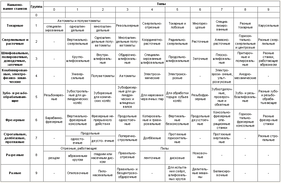
The third and sometimes the fourth digits indicate the dimensions. The letter between 1 and 2 numbers indicates that this is an upgraded model. If the letter is at the end of the marking, then it indicates the characteristic of the upgrade of the base model. The letters P, B, A, C - indicate the accuracy class. Ш indicates the wide versatility of the model, which, in addition to the horizontally located spindle, has a trunk with a vertical head. G indicates that this machine is a horizontal milling machine.
If you find an error, please highlight a piece of text and click Ctrl+Enter.
Modern milling machines, both horizontal and vertical, including CNC milling machines - combine both classic solutions worked out over the years, so the most modern developments of the world machine tool industry. CNC milling machines are one of the most common and in demand in the metalworking market. The main criteria by which metalworking milling machines- availability of CNC and layout: horizontal and vertical milling machines. For vertical milling machines, the spindle axis is located vertically, for horizontal milling machines - horizontally. Our catalog contains both universal milling machines and CNC milling machines only of European production.
Vertical milling machines, universal - these are machines traditional design without CNC, with vertical spindle and horizontal sliding table. They can be equipped with DRO - digital indication devices that simplify the control of movements along the axes. Characterized by simple and robust design, are intended for single and small-scale production.
Analogs of models 6P11, 6T11, 6P12, 6T12, 6P13, 6T13, VM127.
Horizontal milling machines, universal - machines without CNC, with a horizontal axis of rotation of the tool and a horizontal movable table. They can be equipped with a digital readout (DRO) to control movement along the axes. Are applied in for single works and small-scale production.
Table sizes: 315x1250, 375x1600 mm.
Horizontal console milling machines, universal - machines without CNC, with a horizontal axis of rotation of the tool and a horizontal movable table. They can be equipped with a digital readout (DRO) to control movement along the axes. Are applied in for single works and small-scale production.
Analogs of models 6P81, 6T81, 6P82, 6T82, 6P83, 6T83.
Table sizes: 400x1600, 450x1800 mm.
Widely universal console milling machines - without CNC, combining the possibilities of both horizontal and vertical layout. They have two spindles: vertical and horizontal. This allows you to use one instead of two machines, significantly saving production area. Machine tools can be equipped with a digital indication device (DRO) to control movement along the axes. They are used for single works and small-scale production.
Analogues of machines 6R82Sh, 6T82Sh, 6R83Sh, 6R83Sh.
Table sizes: 315x1250, 375x1600, 400x1600, 450x1800 mm.
Vertical milling CNC machining centers - machines of the classical layout: the spindle is located vertically above the horizontal movable table. The table moves in two perpendicular horizontal axes, the headstock moves vertically. It provides processing of details in 3 coordinates - a standard basic complete set. The machines are available in both 4- and 5-axis versions, equipped with an automatic tool changer with tool magazines, and represent a simple and inexpensive solution combined with great versatility.
CNC horizontal machining centers - machines with a horizontal spindle. The table of such a machine, as a rule, is also located horizontally. The advantages of such a machine are in the greater rigidity of the table-spindle system, as well as in good chip removal from the cutting zone. At the same time, they, as a rule, have larger dimensions than vertical layout machines. Often, such machines are equipped with a pallet (table) change system, which reduces the time for removing and installing the workpiece.
Analogues of domestic models IR 500, IS 500, IR 800, IS 800.
CNC vertical milling and turning machining centers are the most modern machines that combine the capabilities of a milling machining center and a CNC vertical lathe. The machine can be equipped with 1-2-3-axis milling spindle, spindle head changing system, turning and grinding spindle. The automatic head and tool change system allows you to perform the maximum number of operations in one installation of the workpiece, reducing the time for reinstalling the part, reconfiguring the machine and eliminating inaccuracies that occur when reinstalling the workpiece. In addition, by combining the lathe and milling machine into one design, the designers almost halved the required production area.
Heavy milling machines with a movable table and a horizontal spindle are available with both a movable and a fixed column. They are equipped with interchangeable milling heads for the tasks of the Customer. These can be both ordinary milling or boring heads, and angular, as well as 2-3-axis. The machines are equipped with automatic magazines for interchangeable heads and tools. The configuration of the machine, movements along the axes, the design and dimensions of the tables are selected according to the requirements of the customer.
Heavy milling machines with a movable rotary table - machines with a fixed column, on which a spindle with a horizontal axis of rotation and the possibility of vertical movement is located. The remaining movements are provided by the mobility of the table. A wide range of table sizes and cutter head configurations allows for the machining of complex workpieces with high cutting forces.
Heavy milling machines with a moving column are machines with a horizontal spindle axis. The movable column of machines can move along the table of considerable length - up to 25 meters. Machines of this type are a basic module, for which a table of the required size is selected, or several tables (for example, the main fixed table and a small rotating table). Machines can be equipped automatic systems changing tools and milling heads for the required number of positions.
Heavy portal milling machines with a sliding table are U-shaped machines with a vertical spindle axis. The spindle provides vertical and transverse movement, and the longitudinal movement is provided by a movable table. This design is the simplest and most common, has high rigidity and excellent dynamic parameters. Offered wide selection milling heads of various configurations for processing parts of any complexity.
Heavy portal milling machines with a movable portal - machines, the portal of which moves entirely above a fixed table along guides located along the table on both sides. The machines feature a rigid stable structure and high dynamics, and big choice configurations and sizes of tables, as well as milling heads, allows you to process parts of complex configurations.
Gantry milling machines with moving traverse are heavy machines with the highest dynamics and precision. The horizontal traverse of the machine, together with the vertical spindle, moves above the table along the guides located on top of the side support columns located on the sides of the fixed table. Due to the minimum weight of the traverse/spindle system and the completely symmetrical design, the machine allows high movement dynamics with maximum rigidity and stability of the structure.
Milling machines from Europe - the best choice
In our catalog you can choose on your own, or with the help of our specialists, milling machines European manufacturers, to solve any problem and for any budget. We draw your attention to the fact that our company is not limited to these manufacturers - we specialize in the supply of any European equipment. The catalog contains manufacturers of machine tools with whom good relations have developed over the years, and the machines have confirmed their quality over the years of operation in Russian conditions.
Help in choosing
Our specialists, having extensive experience in supplying European machines to Russia, will be happy to help you decide on the supplier and model of milling machines, taking into account all the tasks and needs of the Customer.
How to buy?
Contact our specialists by phone, e-mail or through the order forms on the site! You will be able to receive exhaustive answers to all your questions in the shortest possible time. We value our clients! Let us show it off!
OOO Mir Stanochnika offers to buy imported equipment for metal processing in Moscow. Each product is different high quality production and assembly. We are ready to offer profitable terms purchases and independently deliver the goods to the facility.
Showing all 7 results
CNC horizontal metal milling machine has found wide application in various fields of production. It is used for processing large workpieces. In addition, the machine is often operated as a boring machine to create holes of different depths and diameters.
In this type of equipment cutting tool located horizontally, that is, parallel to the floor. The workpiece is fixed on a special table that rotates around its axis, thereby expanding the capabilities of the machine.
Advantages of horizontal milling machining centers:
- Horizontal spindle. Thanks to this, chips do not accumulate around the work surface.
- High speed. Automatic feed tool and blanks allows you to exclude a person from the process of processing materials with a CNC horizontal milling machine.
- High accuracy. The error in the final product is hundredths of a millimeter.
- Ease of use. The machine only needs to set the operating parameters and feed the workpieces.
Benefits of purchasing CNC horizontal milling machines from us
The World of the Machine Tool company provides customers with the most convenient conditions for the purchase of CNC machines:
- Help with choosing. We will offer CNC horizontal milling machine and its accessories according to favorable price based on the needs of a particular company. To do this, our specialist will study the drawings of manufactured parts.
- Delivery of equipment.
- A wide range of products, the presence of most machines in stock.
- Formation commercial offer within a working day after contacting the company.
We also recommend
 Productive and reproductive thinking
 Reasonable egoism - what is the theory of reasonable egoism?
 Boris Nikolaevich Yeltsin, the first President of Russia
 Underground fights. Underground kings. What is “fighting not for the masses”? Where can you fight for money?
 Yakov Pavlov and Other Heroes of Stalingrad You Need to Know
 Survive an accident at sea in a dream - in reality experience a new love