Scheme of the elevator heating unit. Elevator unit of the heating system: purpose, scheme, dimensions
By popular demand from readers, I post circuit diagram elevator unit with a heat meter. I want to immediately notice the scheme is fully working, slightly adapted for viewing on the Internet with comments.
Scheme of an elevator unit with a heat meter 2013, and in order to fully comply with the new rules for the commercial accounting of thermal energy, coolant, registration No. 1034 dated November 18, 2013, only one change needs to be made to it, to transfer the thermal resistance (TE pos 2) that measures the temperature of the coolant in the supply pipeline from the entrance to the site pipes after the flowmeter (FT pos 1a). But this does not affect the concept of the basics of the heat meter and the elevator assembly.
Elevator node in this scheme with automatic control, but this does not mean that the scheme of the elevator unit with a heat meter will not work without automatic weather control, moreover, its implementation can be divided into two stages, which will allow the project to be implemented with a lack of finances.
Just take note for yourself, such savings are beneficial if you started installation immediately after the end of the heating season, if heating season on the nose it is better to pull yourself up and install everything at once. Usually, during the heating season, heat meters and especially weather-dependent automation pay for themselves.
The price of installing an elevator unit with a heat meter.
I'll go over the prices right away. They are relevant at the end of 2014 and take into account a 10% increase in prices associated with the instability of the dollar and euro. Contractual prices, for interest, you can find out the estimated price by increasing these prices by 25%.
Installation of a heat meter in a standard five-story building from 4 to 6 entrances, without separate pipes for hot water from a heat source (two-pipe heat supply system):
– without control elevator – 160 tr.
- with a regulating elevator operating in automatic mode depending on the temperature outside - 290 tr.
It should also be noted that the price mains or circulation pump not taken into account if the hydraulic mode from the boiler room (pressure drop) is less than 7m, you will need to install it, otherwise the elevator simply will not work. The price of such pumps is usually in the range of 600 - 1000 euros, it all depends on the size of the house.
As you can see, it is not cheap, but I repeat once again, the installation of an elevator unit with a heat meter and automatic weather control will pay for itself in a maximum of two years, and if you are overheated, then in the heating season.

Let's return to the scheme of the elevator unit with a heat meter. It contains all the necessary explanations. As a calculator of the amount of heat, a well-proven and easy-to-maintain heat meter VKT 7 from Teplocom is used. Electromagnetic flowmeters PREM - also from this company. The control elevator and the automatic weather control itself are manufactured in Belarus. It should be noted inexpensive very reliable and thoughtful option. In Russia, its full copy is produced, but for some reason it is 30% more expensive, I can’t judge the reliability of domestic automation - it has not been tested.
If someone has any questions about the scheme, project, the possibility of installation by our enterprise or just the operation of this scheme of an elevator unit with a heat meter, call - 8 918 581 1861 Yuri Olegovich.
For those who missed
Today it is impossible to imagine your life without heating. Even in the last century, the most popular was the oven.
Not many people use it these days. The most. All the air rises and thus the floor is not heated.
Technological progress has come a long way. And now the most profitable and popular is the water heating system. Of course, to ensure comfort in the house, heat is of great importance.
Regardless of whether it is an apartment, or private house. However, it must be remembered that the type of heating depends on the type and category of housing. In private houses, individual heating is installed.
But most apartment dwellers still use centralized heating system which requires no less attention.
The elevator assembly is one of the main components of the system. However, not many people know what functions it performs. Let's look at its functional purpose.
What is it and what is it used for

Working device in the basement
The easiest way to find out what an elevator node is is to visit the basement of an ordinary high-rise building.
Among the many details of the heating system, it will not be difficult to find this important component.
Consider a simple circuit. How does heat enter the house? There are two pipelines: supply and return. The first is the eyeliner hot water To home. With the help of the second, it already gets into the boiler room cold water from the system.
The thermal chamber supplies hot water to the basement of the house. Please note that a shut-off valve must be installed at the entrance.
It can be a simple gate valve, or steel ball valves. The temperature of the coolant determines how it will work further. There are three main levels of heat:
- 150/70°C
- 130/70°C
- 95 (90)/70°C
If the temperature of the heat carrier is not higher than 95 ° C, then it remains only to distribute the heat throughout the heating system. This is where a manifold with balancing valves comes in handy.
However, everything becomes not so simple if the temperature of the coolant goes beyond the norm of 95 ° C. Such water cannot be run into the heating structure, so the heating must be reduced. This is precisely the important function of the elevator assembly.
Principle and scheme of work

Scheme and principle of operation
The elevator contributes to the cooling of superheated water to a temperature corresponding to the norm.
Then the coolant supplies it to the heating system of residential premises. At the moment when the hot water in the elevator from the supply heat pipe mixes with the cooled water from the return pipe, and cooling occurs.
The layout of the elevator allows you to get acquainted with its functionality in more detail. It is not difficult to understand that it is this part of the heating system that ensures the efficiency of its operation.
It works simultaneously as 2 devices:
- Circulation pump
- Mixer
The design of the elevator is quite simple, but effective. Differs in an acceptable price. It does not need to be connected to work. electricity. However, there are some disadvantages that you need to pay attention to:
- The pressure in the forward and reverse transmission pipelines must be maintained within 0.8-2 bar;
- Outlet temperature cannot be adjusted;
- Each element of the elevator must be accurately calculated.
It is safe to say that the devices are widely used in the municipal heating system.

The efficiency of their work is not affected by fluctuations in the thermal and hydraulic regime in heating networks. In addition, the devices do not require constant supervision. By selecting the correct nozzle diameter, all adjustments are made.
The main elements of the elevator

The main elements of the node
The main components of the device are:
- jet elevator
- Nozzle
- Vacuum chamber
The elevator heating unit consists of stop valves, control thermometers, manometers. It is also called "elevator piping".
New technical ideas and inventions are rapidly introduced into our lives. Heating is no exception.
The usual elevator units are being replaced by devices that regulate the coolant in automatic mode.
Their cost is much higher, but at the same time, these devices are more economical and energy efficient. In addition, they require a power supply to operate. Sometimes more power is needed. Reliability on the one hand and technological progress on the other.
What will be more important in the end, we will find out over time.
Central heating supply lines for apartment buildings are complex complexes. They transfer heat through pipelines from the supplier to the final consumer. Hot coolant is supplied through a distribution manifold and gradually fills the radiators inside the house. To equalize the temperature, a special device is used - an elevator unit.
Use the elevator assembly to adjust the supply temperature
general description
Before dealing with the scheme of the elevator heating unit, it must be said that, by its design, the elevator is a kind of circulation pump, which is located in the heating system along with pressure meters and valves.
Thermal elevator units perform a number of functions in their work. To begin with, this electronic device distributes pressure in the heating system so that water is delivered to consumers in heating batteries with a certain pressure and temperature. During circulation through pipes from the boiler room to multi-storey buildings the volume of the heat carrier in the circuit is almost doubled. This can only happen if there is a supply of water in a separate sealed container.
Most often, a heat carrier is supplied from the boiler room, with a temperature of about 110-160 ℃. For domestic needs, in terms of safety, these high temperature indicators are unacceptable. Maximum temperature regime the coolant in the circuit cannot be more than 90℃.
From this video we learn the principle of operation of the elevator heating unit:
It is also noteworthy that in the SNiP today the temperature standard for the coolant is indicated in the range of 65 ℃. But in order to save resources, there is an active discussion regarding the reduction of this standard to 55℃. Taking into account the opinion of experts, the consumer will not feel a significant difference, and as a disinfection, the heat carrier will need to be heated to 75℃ once a day. However, these changes to the SNiP have not yet been adopted, since there is no exact opinion regarding the effectiveness and expediency of this decision.
The scheme of the elevator unit of the heating system makes it possible to bring the temperature regime of the heat carrier to the regulatory requirements.
This device helps to prevent the following consequences:
- if the wiring is made of propylene or plastic pipes, then it is not designed for the supply of hot heat carrier;
- not all heating pipes are designed for prolonged exposure to elevated temperatures under high pressure - these conditions will lead to their rapid failure;
- Very hot heating radiators can cause burns if not handled carefully.
Elevator Advantages
Many consumers say that the heating elevator scheme is irrational, and it is much easier to supply users with a coolant at a lower temperature. In fact, this approach implies an increase in the diameter of the central heating pipeline for the circulation of a colder coolant, which implies additional costs.
That is, a high-quality scheme of the heating unit allows using part of the cooled water from the return with the supply volume of the coolant. Although some sources of elevators are old hydraulic devices, in fact, they are the most efficient. There are also more modern devices that have replaced the systems of the elevator unit.
This includes the following types of devices:
- mixer equipped with a three-way membrane;
- plate heat exchanger.
Principle of operation
Considering the scheme of the heating elevator, one cannot fail to note the similarity finished equipment with water pumps. And for work it is not necessary to receive energy from other systems.
By appearance the main part of the device resembles a hydraulic tee, which is installed on the return circuit of the heating system. Through an ordinary tee, the coolant would calmly pass into the return line, bypassing the batteries. This scheme of the thermal unit would be impractical.
IN standard scheme heating elevator the following items are found:
- A preliminary chamber and a heat carrier supply pipe with a nozzle of a certain diameter installed at the end. Water from the return circuit circulates through it.
- A diffuser is installed at the outlet, which is designed to supply the coolant to users.

Regulation of the heating system can be done both manually and with the help of technology
To date, you can find nodes in which the size of the nozzle is controlled by an electric drive. As a result, the required temperature of the circulating water can be automatically adjusted.
The choice of the scheme of the heating unit with an electric drive is made taking into account the fact that it is possible to change the mixing ratio of the heat carrier in the range of 3-6 units. This cannot be done in elevators where the nozzle section does not change. Thus, units with an adjustable nozzle can significantly reduce heating costs, which is important for multi-storey buildings with central meters.
Heating unit scheme
If the heating system uses a heating unit scheme apartment building, then its high-quality work can be organized only on the condition that the working pressure between the return and the supply circuit is higher than the calculated hydraulic resistance.
The scheme of operation of the elevator in the thermal unit is as follows:
- hot heat carrier is fed through the central pipeline to the nozzle;
- circulating through pipes of small diameter, the coolant begins to increase speed;
- moreover, a discharged zone appears;
- the resulting vacuum “sucks” water from the return circuit;
- turbulent water flows through the diffuser to the outlet.
Main disadvantages
Despite the fact that the elevator assembly has many advantages, it also has one significant drawback. It's just that the elevator circuit does not provide for the possibility of adjusting the temperature of the outgoing heat carrier.
If the temperature of the water in the return circuit indicates that it is very hot, then it will need to be lowered. This problem can be solved only by reducing the size of the nozzle, but this can not always be done due to the design features of the equipment.
In some cases, the heating unit is equipped with an electric drive, thanks to which the size of the nozzle can be adjusted. He moves the main structural element - a throttle cone needle. This needle moves a certain distance into the hole inside the nozzle. The depth of movement makes it possible to change the diameter of the nozzle and thereby regulate the temperature of the heat carrier.
It is possible to install both a manual drive in the form of a handle and a remotely controlled electric motor on the shaft.
It must be said that the installation of this temperature controller makes it possible to improve the overall heating system with a thermal unit without significant material costs.
Possible malfunctions and repairs
Despite the reliability of the equipment, in some cases the elevator heating unit may fail. hot coolant and high blood pressure quickly find vulnerable areas and provoke the failure of this device. This inevitably happens if individual elements have a poor-quality assembly, the calculation of the nozzle size is incorrect, and also due to the appearance of blockages.
Noise in the heating pipe. The elevator heating unit can create noise during its operation. If this is noted, it means that irregularities or cracks appeared at the nozzle outlet during operation.
The reason for the formation of these defects is the misalignment of the nozzle, which is caused by the supply of hot water under high pressure. This can happen if the excessive head is not throttled by the flow regulator.
Wrong temperature setting
The high-quality operation of the heating elevator can be called into question if the temperature at the inlet and outlet circuits differs significantly from temperature chart. Most likely, the reason for this is the oversized nozzle.
Incorrect coolant flow
A faulty throttle can lead to a change in the flow rate of the coolant, in contrast to the design indicator.
This violation can be easily determined by changing the temperature in the supply and return pipes. The problem can be solved by repairing the flow regulator.
Faulty assembly parts
If the scheme for connecting the heating system to the external main is independent, then the reason for poor-quality operation of the elevator can be caused by faulty water heating elements, circulation pumps, protective and shutoff valves, various leaks in equipment and pipes, failure of regulators.
The main reasons that negatively affect the principle of operation and the scheme of pumping equipment include the destruction of elastic membranes in the joints of the shafts of the electric motor and the pump, the wear of bearings and the failure of the seats under them, the appearance of cracks and irregularities on the housing, the leakage of oil seals. All of the above breakdowns can only be repaired.
Poor-quality operation of water heaters can be observed if the tightness of the pipeline is broken, sticking or destruction of the pipe assembly occurs. The only way to solve the problem is to replace the pipes.
Blockages and pollution
Blockages are one of the most common causes poor quality heating. Their appearance is due to the ingress of dirt into the heating system, if the mud filters do not cope with their task. Corrosion growths inside the pipeline can also increase the problem.
The level of contamination of the filters can be found from the pressure gauges that are installed near the filter and behind it. A strong pressure drop can confirm or refute the assumption about the level of contamination. To clean the filters, remove dirt through bleed valves located at the bottom of the case.
Any malfunctions in the system of heating equipment and pipes must be corrected immediately!
Any remarks that do not affect the operation of the heating system without fail must be registered in special documentation, it must be included in the plan for capital or current work on the repair of equipment. Troubleshooting should be carried out in the summer before the heating season.
The heat carrier in district heating systems passes through heating point before getting directly into the radiator sections of each apartment and individual room. In such a node, the water is brought to the design temperature, and the balance is ensured due to the fact that the circuit of the elevator heating unit is working correctly. In the basement of any multi-storey building heated along the central highway, you can find such an elevator.
The principle of operation of the node
Understanding what an elevator is, it is worth noting the need for this complex to connect heating networks and private consumers with it. A thermal unit is a module that performs the functions of pumping equipment. To see what an elevator is in a heating system, you need to go down to the basement of almost any apartment building. There, among the shut-off valves and pressure meters, it will be possible to find the desired element of the heating system (the diagram is shown in the figure below).
.jpg)
Finding out what an elevator is, it is worth determining its functionality according to the tasks performed. These include the redistribution of pressure from inside the heating system, while the coolant is issued with allowable temperature. In fact, the volume of water doubles, moving along the highways from the boiler room. This effect is achieved in the presence of water in a separate sealed vessel.
The temperature of the heat carrier coming from the boiler room is usually in the range of 105-150 0 C. Use it with this parameter in living conditions not possible for security reasons.
Regulatory documents the boundary temperature value for the coolant is regulated, which should be no more than 95 0 С.
For reference. Currently, the issue of reducing the temperature of hot water from 60 0 C, provided for by SanPin, to 50 0 C, is being actively discussed, citing the need to save on resources. According to experts, the consumer will not notice such a minimal difference, and in order for proper disinfection of water in pipes to be carried out daily, it is recommended to increase it to 70 0 C. It is too early to judge how rational and thoughtful this initiative is. Changes to SanPin have not yet been made.
Returning to the topic of the heating system elevator, we note that it is he who provides the temperature in the system. These steps help reduce the risk of:
- with excessively overheated batteries, it is easy to get burned;
- heating radiators are not always able to withstand long time exposure to elevated temperature of the coolant under pressure;
- wiring made of polymer or metal-plastic pipes does not provide for their use with such hot heat transfer fluids.
How convenient is this node

You can hear the opinion that it would be more convenient not to use a heating elevator with this principle of operation, but to directly supply water at a lower temperature. However, this opinion is erroneous, because it will be necessary to significantly increase the diameters of the lines to transfer a colder coolant.
VIDEO: Elevator node of the central heating main
In fact, a competent scheme of a thermal heating unit allows you to mix part of the volume from the return, which has already cooled down, into the supply volume of water. Although in some sources the elevator assembly of the heating system is classified as outdated hydraulic equipment, it has proven its effectiveness in operation. More modern devices used instead of the elevator assembly scheme are the following types:
- plate heat exchanger;
- mixer with three-way valve.
Operation of the elevator
Considering the elevator unit of the heating system, what it is and how it works, it is worth noting that working structure there are similarities with water pumps. However, operation does not require the transfer of energy from other systems. It shows its reliability under certain conditions.
Outside basic part device is externally similar to a hydraulic tee mounted on the return branch. However, through a standard tee, the coolant would painlessly penetrate into the return line without passing through the radiators. Such behavior would be meaningless.
.jpg)
Standard elevator layout
In the classical scheme of the elevator unit of the heating system, the following components are present:
- A prechamber, a supply pipe, at the end of which there is a nozzle of a certain diameter. It receives the coolant from the return.
- A diffuser is installed in the outlet part. It delivers water to consumers.
Today there are nodes where the diameter of the nozzle is controlled by an electric drive. This makes it possible to optimize the temperature of the coolant in automatic mode.
The choice of a unit with an electric drive is based on the fact that it is possible to change the mixing ratio of the coolant within 2-5, which is impossible in elevators where the nozzle diameter is not adjustable. Thus, a system with an adjustable nozzle allows significant savings on heating, which is possible in houses where central meters are installed.

Structure
How does the thermal node scheme work?
In general, the principle of operation can be described as follows:
- water moves along the line from the boiler room to the entrance to the nozzle;
- during the passage along a small diameter, the speed of the working coolant increases significantly;
- an area with a small discharge is formed;
- due to the resulting vacuum, water is sucked from the return;
- turbulent flows in a homogeneous mass are sent to the outlet through the diffuser.
In more detail, you can see everything on the working diagram.
For effective work system, in which the scheme of the elevator unit of the heating system is involved, it is necessary to ensure that the value of the pressure values between the supply and return is greater than the value of the calculated hydraulic resistance.
System Disadvantages

In addition to positive qualities, a thermal node or a thermal node circuit has a certain disadvantage. It consists of the following. The elevator of the heating system does not have the ability to adjust the output temperature mixture. In such a situation, it will be necessary to measure the heated coolant from the main or from the return pipeline. It will be possible to lower the temperature only by changing the dimensions of the nozzle, which cannot be done structurally.
In some cases, elevators with an electric drive are saved. Their design includes a mechanical drive. This unit is powered by electric drive. In this way, it is possible to vary the diameter of the nozzle. The basic element of this design is a throttle needle having cone view. She enters the hole inner diameter designs. Moving a certain distance, it manages to correct the temperature of the mixture precisely by changing the diameter of the nozzle.
Both a manual drive in the form of a handle and a remotely started electric drive engine can be mounted on the shaft.
Due to such modernized solutions, the boiler room in the basement does not undergo significant costly refurbishments. It is enough to mount the regulator to get a modern heating unit.
Faults

In most cases, breakdowns are caused by the following factors:
- equipment clogging;
- a gradual increase in the diameter of the nozzle during operation, as a result of which the temperature of the coolant is more difficult to control;
- clogged mud tanks;
- breakage of fittings;
- failure of regulators, etc.
It is not difficult to determine the breakdown of this device, it immediately affects the temperature of the coolant and its sharp drop. With minor deviations from the norm, most likely, we are talking about clogging or a slight increase in the diameter of the nozzle. If the difference is very significant (more than 5 degrees), then it is already necessary to carry out diagnostics and call a specialist for repair.
The diameter of the nozzle increases either in the process of corrosion in contact with water, or as a result of involuntary drilling. Both ultimately lead to an imbalance in the system and must be eliminated immediately.
You need to know that modern modernized systems can be operated with electricity consumption metering units. With absence this device in the heating circuit it is difficult to achieve an economical effect. Installing heat and hot water meters can significantly reduce utility bills.
VIDEO: The principle of operation of the node
The supply of coolant to the heating appliances of residential premises should be carried out in accordance with design parameters and technical specifications. Long distances of transportation and peculiarities of the climate require the creation of a certain thermal regime, in most cases not allowing direct supply to apartments. A system for adjusting the temperature of the coolant is needed to ensure that its parameters and the capabilities of pipelines and radiators correspond. Consider the elevator unit of the heating system, which is the main element for regulating the general thermal regime of an apartment building.
What is an elevator assembly of a heating system
The main heat supply networks operate in three main modes:
- 95°/70°
- 130°/70°
- 150°/70°
The first number indicates the temperature of the coolant in the direct pipeline, the second - in the return. The coolant is transported over considerable distances, so the temperature is set with the calculation of thermal energy losses during movement and adjusted for climatic or weather. Hence the three options for supplying the coolant - if you constantly heat the water to the maximum value, the fuel consumption will increase, so the heating modes change depending on external conditions.
According to sanitary standards And technical specifications household thermal equipment, the upper limit of the coolant temperature must not exceed 95°. If the water is heated to 130° or 150°, it must be cooled to the set value. There are several reasons for this:
- Most heating appliances are not able to work with superheated water - cast iron radiators become brittle, aluminum may fail or cease to hold system pressure.
- Pipelines used for supplying coolant to apartments also have a temperature limit, for example, a temperature threshold of 90 ° is set for plastic pipes.
- Too hot heaters are dangerous for people, especially for children.
Superheated water does not turn into steam just because there is no such possibility inside the pipelines. It requires the absence of pressure and the presence of free space, which cannot be in the pipe. Temperature losses during transportation somewhat change the thermal regime of the coolant, but the need for its cooling to operating values remains. The issue is solved by mixing in chilled water from the return pipe until the desired temperature is obtained, suitable for use in heating appliances. Mixing of water occurs in special mechanical devices - elevators. They work in an environment of related elements called the elevator environment, and the entire mixing node is called the elevator node.
Principle of operation and device
The elevator is a steel or cast-iron body with three nozzles (two inlets and one outlet), resembling a regular tee.
The coolant enters the housing and passes through the nozzle, causing its pressure to drop. This causes the return flow from the pipeline to the mixing chamber, which circulates in the heating system. The flows, mixing, acquire a given temperature, then they are sent through a diffuser to the heating system of the apartment. A conventional elevator is a purely mechanical device, which makes it as easy to use as possible. The adjustment is made by changing the diameter of the nozzle, which creates a certain pressure in the mixing chamber, changing the return suction mode. In this case, the pressure difference between the direct and return pipelines should not exceed 2 bar. For getting correct result required exact calculation nozzle diameter, since this is the only element subject to any changes. Otherwise, the elevator is a one-piece cast iron casting, relatively inexpensive, reliable and very easy to operate and maintain. These reasons caused wide use elevators in heating systems of apartment buildings.
There are more complex designs of elevators with the ability to change the diameter of the nozzle. These devices are more expensive and complex, but they allow you to change the operating mode of the heating system on the go, depending on the pressure and temperature of the coolant in the line. The passage of the coolant is regulated by a cone-shaped rod - a needle that moves in the longitudinal direction and opens or closes the nozzle lumen, changing the operation mode of the elevator and the entire system. There is a device with a servo drive that is able to adjust the clearance on the go according to a signal from temperature or pressure sensors, which allows you to fine-tune the work in automatic mode. Such devices are more expensive and require increased attention and care, but they create a lot of new possibilities for adjusting the system.
Scheme of the elevator unit of the heating system
Independent operation of the elevator is not possible. The elevator assembly includes various elements:
- Gate valves (recently replaced by Ball Valves, more convenient and reliable in operation).
- Gryazeviki.
- Pressure gauges.
- Thermometers.
- Connecting elements (flanges or adapters).
The schematic diagram of the elevator unit can be seen in the figure:
 Elevator unit in the heating system: 1- shutoff valves (valve); 2 - sump; 3 - water jet elevator; 4 - pressure gauge; 5 - thermometer
The main elements are valves that allow you to adjust the parameters of the forward and reverse flow. Mudguards are devices that separate mechanical inclusions in the form of small debris or dirt. They are subject to periodic cleaning, filling the sumps is dangerous and can damage elements located further along the flow path. The remaining elements - pressure gauges and thermometers - are control and allow you to monitor the current mode of the heating system.
Elevator unit dimensions
Elevators are manufactured in several standard sizes, corresponding to the size and needs of the heating system of the house or the entrance of an apartment building:
 Table depending on the elevator number and its size
The elevator is selected according to a combination of various parameters - temperature, pressure in the system, bandwidth pipelines, connecting dimensions, etc. Most devices are selected based on the diameter of the pipes that feed the heating system. It is important to ensure that the diameter of the supply pipelines and the dimensions of the elevator nozzles correspond, so that the device does not turn out to be a kind of diaphragm that reduces the throughput and pressure in the system. In addition, the size of the nozzle, which must be carefully calculated, affects the efficiency of work. Calculation formulas are available on the network, but it is not recommended to produce it on your own, without experience and training. The easiest way is to use an online calculator that can be found on the Internet. It is advisable to check the result obtained on another calculator in order to get a more correct result.
How to maintain
The operation of the elevator is based on the action of physical laws, therefore, its design does not provide for any moving or rotating parts. Even in more complex structures with a changing nozzle size, a special needle moves, increasing or decreasing the passage for the coolant (according to the principle of operation of the spray gun), which does not have high speed movement. Therefore, all care for the device consists in timely cleaning of contaminants, removing dirt, which is gradually accumulating due to the poor quality of the coolant. Nozzles are subject to periodic replacement, which are under load when exposed to a stream of hot water and are the first to fail. Checking the diameter and condition of the nozzle is carried out annually, replacement is carried out when necessary - severe wear of the part, excessive increase or decrease in throughput. It is also necessary to monitor the tightness of flange connections, change gaskets and seals in time.
Advantages and disadvantages
The advantages of elevator temperature control in the heating system include:
- The simplicity of the device, the ability to maintain a constant ejection coefficient of the coolant, which means a constant temperature of the mixture going into the heating system.
- Reliability, ability to work in difficult conditions.
- Few parts to be replaced.
- No power connection required.
- Combination of two functions - mixer and circulation pump, with a simple design.
- Quiet operation.
There are also disadvantages:
- The need to ensure the difference between the pressures of the direct and return lines within 2 bar.
- The ability to work in a single mode without changing the nozzle (except for adjustable devices).
- Low efficiency, forcing to increase the pressure of the coolant in front of the elevator unit (this is especially true when used in heating systems of private houses operating from their own boiler).
- In the event of a failure on the main line, the circulation stops, which can result in cooling and freezing of the system.
- You cannot use one node for several buildings.
disadvantages elevator systems offset by their efficiency, simplicity and reliability, which has led to widespread use.
Wiring diagrams
The elevator unit can be used in systems with various specific features - single-pipe, autonomous or other heat supply lines. The principles of coolant supply, flow parameters do not always allow for a constant and stable output result. To organize the normal heat supply of apartments or adjust the parameters of the flow coming from the main network, various schemes for connecting elevator nodes are used. All of them need to be available additional equipment, sometimes in fairly large volumes, but the result that is achieved as a result of this compensates for the costs incurred. Consider the existing connection schemes:
With water flow regulator
The water consumption is the main factor that makes it possible to regulate the space heating mode. Changes in flow cause temperature fluctuations in living rooms, which is unacceptable. The issue is solved by installing a regulator in front of the mixing unit, which provides constant flow water and stabilizing thermal conditions.
 Scheme of an elevator mixing unit with a flow controller: 1 - supply line of the heating network; 2 - return line of the heating network; 3 - elevator; 4 - flow regulator; five - local system heating
This decision becomes especially important in single pipe systems, where there is a load in the form of hot water supply, which destabilizes the flow of hot water and creates significant fluctuations during active water intake (morning and evening hours, holidays and weekends). Wherein this scheme is not able to correct the situation with changes in the temperature of the coolant in the main line, which is its disadvantage, although not too significant. A drop in the temperature of the coolant in the supply pipelines means an accident at the CHP or other heating point, and this rarely happens.
with regulating nozzle
The connection scheme of the elevator unit with the ability to adjust the throughput of the nozzle allows you to quickly respond to changes in the parameters of the coolant in the main line.
 Scheme of an elevator assembly with a regulating needle: 1 - supply line of the heating network; 2 - return line of the heating network; 3 - elevator; 5 - local heating system; 6 - regulator with a needle inserted into the elevator nozzle
At the same time, manual adjustment is ineffective, since for this it is necessary to constantly approach the elevator, which is usually located in basement. The most efficient system with an adjustable nozzle is achieved when the process is fully automated, using temperature and pressure sensors that send a signal to the elevator servo. Such a scheme allows you to get additional features when setting the operating mode, but the need for it does not always arise, but only in overloaded or unstable systems with possible fluctuations in the temperature of the coolant.
 Scheme of an elevator assembly using temperature and pressure sensors that send a signal to the elevator servo drive
It is customary to attribute the disadvantages of such schemes to the need to initially ensure high pressure in the system, since adjustment is possible only within the flow parameters in the line. In addition, the loads on the mechanics, in particular - on the nozzle and needle, create the need for constant monitoring and timely replacement of failed elements.
with regulating pump
Such schemes are used in the absence of pressure sufficient for the operation of the elevator in the supply pipelines.
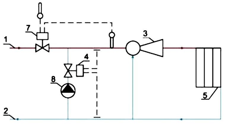 Scheme of an elevator unit with a corrective pump: 1 - supply line of the heating network; 2 - return line of the heating network; 3 - elevator; 4 - flow regulator; 5 - local heating system; 7 - temperature controller; 8 - mixing pump
The increase in pressure makes it possible to use the elevator unit in autonomous heating networks of a private house, allows the circulation of the coolant when the pressure in the line disappears. The pump is installed in front of the elevator or on the jumper between the direct and return pipelines before entering the elevator. To ensure normal operation, a temperature controller is required in addition to the pump, and an electrical connection is also required.
Main malfunctions
Possible malfunctions are usually associated with the failure of the nozzle under the aggressive action of hot water. There are also clogging of the mud collectors, breakage of valves or regulators. All these malfunctions are associated with difficult operating conditions of the equipment - water pressure and its temperature contribute to the rapid destruction of the metal, the occurrence of electrochemical corrosion. If signs of malfunctions appear, which are usually expressed in temperature fluctuations, a change in the heating mode and other unstable phenomena, it is necessary to revise the device, replace the nozzle, clean the mud collectors, replace or adjust the dampers. In general, the operation of the elevator units is quite stable and does not create any particular problems.
The elevator is a simple and reliable device that can operate in a stable mode and does not require the use of electricity. These reasons led to the widespread use of such equipment, which is gradually beginning to give way to more modern devices based on the same elevator, but with enhanced capabilities. However, the use of simple mechanical devices does not stop, their reliability and low cost are still attractive to users.
We also recommend
 Switching power supply: repair and refinement
 Remote control of light
 Swimming lessons for preschool children
 Notes for the master - home household alarms
 Clock propeller on Atmega8
 Device and relay application examples, how to choose and connect a relay correctly Microcontroller and relay simple switching circuits