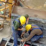
Do-it-yourself cnc machine assembly drawings. CNC milling machine at home (garage) conditions
In order to perform a three-dimensional drawing on wooden surface, factory milling machines are usually used. But it is quite possible to make such a mini-model on your own, but first you need to familiarize yourself with the design. The basis can be a spare part from a printer, which can be purchased for a penny.
The principle of the machine
If you decide to make a CNC router with your own hands, you should familiarize yourself with the features of the operation of such equipment. It is designed to form a pattern on a wooden surface. The design should include electronic and mechanical parts. Together they allow you to automate the work.
For the manufacture of desktop machine you should know that the cutting element is a milling cutter. It is installed in the spindle on the shaft of the electric motor. The whole structure is fixed on the frame. It can move along two coordinate axes. To fix the workpiece, a support table should be made. With stepper motors, an electronic control unit must be connected.
The motor and control unit provide displacement of the carriage in relation to the workpiece. This technology allows you to perform three-dimensional drawings on the surface. Mini-equipment works in a certain sequence. At the first stage, a program is written that will allow you to prepare a plan for moving the cutting part. For this, software systems are used for adaptation in self-made models.
The next step is to install the workpiece. The program is entered into the CNC. The equipment is turned on, and then automatic actions are monitored. In order to ensure maximum automation, it is necessary to draw up a diagram and select components.
Before you start making a CNC router with your own hands, you need to familiarize yourself with the factory models. To obtain complex patterns and patterns, several types of cutters should be used. You can do some of them yourself, but for fine work you will need factory options.
Scheme of a homemade machine

The most difficult and important stage in the manufacture of the described equipment is the choice of the scheme. It will depend on the degree of processing and the size of the workpiece. For living conditions it is better to use a mini-machine that will be installed on the table. Suitable option is a design of two carriages that will move along the coordinate axes.
The bases can be ground metal rods. Carriages are installed on them. To create a transmission, you will need stepper motors and screws, which are complemented by rolling bearings. To automate the process, it is necessary to think over the electronic part. It will consist of:
- power supply;
- controller
- drivers.
When making a CNC router with your own hands, you should familiarize yourself with design features devices. For example, a power supply is required to supply power to the stepper motors and the controller chip. For this, a 12V 3A model is used. The controller is required to send commands to the engine. For the operation of the device, a simple circuit for the controller will suffice, which will give commands to three engines.
The driver is also an element of regulation. He will be responsible for the moving part. For management, standard software systems should be used. One of them is KCam, which has a flexible structure to adapt to any controller. This complex has one important advantage, which is the ability to import files of common formats. Using the application, you can create a three-dimensional drawing of the workpiece for analysis.
In order for stepper motors to work with a given input frequency, it will be necessary to enter into the control program technical specifications. When compiling a program, separate blocks should be made. They are designed for:
- drawing;
- milling;
- engravings;
- drilling.
This will eliminate the idle movement of the cutter.
Selection of components

Before making a DIY CNC router, you must select the components to assemble. A suitable option is the use of improvised means. The basis of the machine can be plexiglass, aluminum or wood. For the correct functioning of the complex, it is necessary to develop the design of the calipers. Their movement should not be accompanied by vibrations, which can cause inaccurate processing of the part.
Components are checked for compatibility before assembly. As for the guides, they will be ground steel bars with a diameter of 12 mm. For the X axis, the length is equivalent to 200 mm, for the Y - 90 mm. Before you start making a CNC router with your own hands, you must choose a caliper. Textolite is a suitable option. The dimensions of the site will be as follows: 25x100x45 mm.
The cutter attachment block can be made of textolite. Its configuration will depend on the tool you have. The power supply is usually used factory. If you want to do this work yourself, you must be prepared to possible mistakes which will adversely affect the operation of the equipment.
If you want to assemble a router with your own hands, then you can use the 24v model for this. 5A is also an excellent option. It is quite often compared to disk drives, the former of which has more impressive power. To solder the controller board, you should use capacitors and resistors in SMD packages. This will reduce the parameters, as well as make the interior space more optimized.
Instructions for the manufacture of the machine

Once all the components have been selected, you can begin to manufacture the device. All elements are pre-checked, which especially concerns their quality and parameters. Special parts must be used to fasten the knots. Their shape and configuration will depend on the chosen scheme.
The design must necessarily have a rise of the working tool. To do this, use a toothed belt to return rotation. Mandatory element equipment is the vertical axis. It can be made from aluminum plate. This node is adjusted to the dimensions that were obtained at the design stage and entered into the drawing.
Before you make your own CNC router, you can cast a vertical axis using a muffle plate. Aluminum is an excellent material. Two engines are mounted on the body, which will be located behind the axle. One of them will be responsible for the horizontal, and the other for the vertical movement. Rotation must be transmitted through belts. Once all the elements are in place, the machine must be set to manual control and its operation checked. If deficiencies are identified, you can fix them on the spot.
More about stepper motors

CNC units must be equipped with electric stepper motors. As such a motor, you can use the one that will be borrowed from a dot matrix printer. Usually quite powerful elements are installed in them. Matrix units have steel rods based on durable material. They can also be used in a homemade machine.
If you are wondering how to make a CNC router with your own hands, it is recommended that you first consider the photo. They will let you know how to proceed. The design may include three motors, indicating the need to dismantle two dot matrix printers. It is better if the motors have five control wires, because the functionality of the machine will increase several times. When choosing a stepper motor, you should find out the number of degrees per step and the operating voltage. You should also know the winding resistance. This will allow the software to be properly configured.
Shaft mount
If you decide to make a CNC wood router with your own hands, then you can use a stud or nut of the appropriate size as a drive. It is better to fasten the shaft with a rubber cable with a thick winding. The same approach is relevant when attaching the engine to the stud. You can make clamps from a sleeve with a screw. Nylon is used for this. Helpers-tools in this case are a file and a drill.
Machine electronics
The main element of the described equipment is software. You can use a homemade one that will provide all the drivers for the controllers. The provision must have power supply units and stepper motors. If you are faced with the task of how to assemble a CNC router with your own hands, you must take care of the presence of an LPT port. It will also be necessary working programm, providing control and management of the necessary modes of operation.
The CNC unit itself is connected to the equipment through the port and installed motors. When choosing software for a machine tool, you need to bet on one that has already proven its stable operation and functionality. Electronics will affect the quality and accuracy of the operations performed. After installing it, you should download programs and drivers.
Do it yourself using the same technology. However, it will only handle thin workpieces. Before operating the device, it is necessary to check the operation of the electronic software and eliminate the shortcomings.
Instead of a conclusion: features of manufacturing a machine from drilling equipment
Before starting work on the manufacture of a CNC router with your own hands, you need to step by step review the instructions. It may involve the use of one or the other circuit diagram, on the basis of which the mini-equipment will work. A drilling machine sometimes acts as such, in which the working head is replaced by a milling head.
The most difficult thing is that you have to design a mechanism that provides movement in 3 planes. This mechanism is usually assembled on the basis of the same carriages from a non-working printer.
Software control is connected to the device. It will be possible to work with such a device with blanks from sheet metal, wood or plastic. This is because the carriages from the old printer, providing movement cutting tool, will not be able to guarantee a sufficient degree of rigidity.
A set with which you can assemble your CNC milling machine.
Ready-made machine tools are sold in China, a review of one of them has already been published on Muska. We will assemble the machine ourselves. Welcome…
UPD: file links
I will still give a link to a review of the finished machine from AndyBig. I will not repeat myself, I will not quote his text, we will write everything from scratch. The title only lists a set with engines and a driver, there will be more parts, I'll try to give links to everything.
And this ... I apologize in advance to the readers, I did not specifically take photos in the process, because. at that moment I was not going to do a review, but I will raise a maximum of photos of the process and try to give detailed description all nodes.
The purpose of the review is not so much to brag as to show the opportunity to make an assistant for yourself. I hope this review will give someone an idea, and it is possible not only to repeat, but also to make it even better. Go…
How the idea was born:
It so happened that I have been associated with drawings for a long time. Those. my professional activity is closely connected with them. But it's one thing when you make a drawing, and then completely different people bring the design object to life, and it's quite another when you bring the design object to life yourself. And if with building things I seem to be doing okay, then with modeling and other applied arts, not really.
So for a long time there was a dream from an image drawn in AutoCAD, to make a whack - and it is in kind in front of you, you can use it. This idea slipped from time to time, but could not take shape in anything concrete, until ...
Until I saw REP-RAP three or four years ago. Well, the 3D printer was a very interesting thing, and the idea to assemble myself took a long time to take shape, I collected information about different models about the pros and cons different options. At one point, by clicking on one of the links, I got to a forum where people were sitting and discussing not 3D printers, but CNC milling machines. And from here, perhaps, the hobby begins its journey.
Instead of theory
In a nutshell about CNC milling machines (I write in my own words intentionally, without copying articles, textbooks and manuals).
A milling machine works exactly the opposite of a 3D printer. In the printer, step by step, layer by layer, the model is built up by fusing polymers, in a milling machine, with the help of a cutter, “everything superfluous” is removed from the workpiece and the required model is obtained.
To operate such a machine, you need the necessary minimum.
1. Base (body) with linear guides and transmission mechanism (can be screw or belt)
2. Spindle (I see someone smiled, but that's what it's called) - the actual engine with a collet into which a working tool is installed - a milling cutter.
3. Stepper motors - motors that allow controlled angular movements.
4. Controller - a control board that transmits voltage to the motors in accordance with the signals received from the control program.
5. Computer with installed control program.
6. Basic drawing skills, patience, desire and good mood.))
The points:
1. Base.
by configuration:
I will divide into 2 types, there are more exotic options, but the main 2:
With movable portal:
Actually, the design I have chosen, it has a base on which guides are fixed along the X axis. A portal moves along the X-axis guides, on which the Y-axis guides are located, and the Z-axis node moving along it.
With static portal
This design also represents itself as a body, which is also a portal on which the Y-axis guides are located, and the Z-axis node moving along it, and the X-axis is already moving relative to the portal.
By material:
The case can be made of different materials, the most common are:
- duralumin - has a good ratio of mass, rigidity, but the price (just for a hobby homemade product) is still depressing, although if there are views on the machine for making serious money, then there are no options.
- plywood - good rigidity with sufficient thickness, low weight, the ability to process with anything :), and the price itself, a sheet of plywood 17 is now quite inexpensive.
- steel - often used on machines with a large processing area. Such a machine, of course, must be static (not mobile) and heavy.
- MFD, plexiglass and monolithic polycarbonate, even chipboard - also saw such options.
As you can see, the design of the machine itself is very similar to both a 3D printer and laser engravers.
I deliberately do not write about the designs of 4, 5 and 6-axis milling machines, because. on the agenda is a homemade hobby machine.
2. Spindle.
Actually, spindles come with air and water cooling.
Air-cooled are cheaper in the end, because. for them it is not necessary to block an additional water circuit, they work a little louder than water ones. Cooling is provided by a back side an impeller, which at high speeds creates a tangible air flow that cools the engine housing. The more powerful the engine, the more serious the cooling and the greater the air flow, which may well inflate in all directions
dust (shavings, sawdust) of the workpiece.
Water cooled. Such a spindle works almost silently, but in the end, anyway, the difference between them in the process of work cannot be heard, since the sound of the material being processed by the cutter will block it. There is no draft from the impeller, in this case, of course, but there is an additional hydraulic circuit. In such a circuit, there must be pipelines, a pump for pumping liquid, as well as a place for cooling (radiator with airflow). Usually not water is poured into this circuit, but either TOSOL or Ethylene glycol.
There are also spindles of various capacities, and if low-power ones can be connected directly to the control board, then motors with a power of 1 kW or more must be connected through the control unit, but this is not about us.))
Yes, often in home-made machines they install direct grinders, or milling cutters with a removable base. Such a decision can be justified, especially when performing work of a short duration.
In my case, a 300W air-cooled spindle was chosen.
3. Stepper motors.
The most widely used motors are 3 sizes
NEMA17, NEMA23, NEMA 32
they differ in size, power and working moment
NEMA17 are usually used in 3D printers, they are too small for a milling machine, because. you have to carry a heavy portal, to which a lateral load is additionally applied during processing.
NEMA32 for such a craft is unnecessary, besides, you would have to take another control board.
my choice fell on NEMA23 with a maximum power for this board - 3A.
Also, people use steppers from printers, but since. I didn’t have them either and still had to buy, I chose everything in the kit.
4. Controller
A control board that receives signals from the computer and transmits voltage to stepper motors that move the axes of the machine.
5. Computer
You need a separate computer (possibly very old) and there are, perhaps, two reasons for this:
1. It is unlikely that you will decide to place a milling machine next to the place where you are used to reading the Internet, playing toys, doing bookkeeping, etc. Simply because the milling machine is loud and dusty. Usually the machine is either in the workshop or in the garage (better heated). My machine is in the garage, it is mostly idle in winter, because. no heating.
2. For economic reasons, computers are usually used that are no longer relevant for home life- heavily used :)
Requirements for the car by and large about nothing:
- from Pentium 4
- the presence of a discrete video card
- RAM from 512MB
- the presence of an LPT connector (I won’t say anything about USB, I haven’t studied the news yet because of the driver that works on LPT)
such a computer is either taken from the pantry, or, as in my case, is bought for next to nothing.
Due to the low power of the machine, we try not to install additional software, i. axle only and control program.
Next are two options:
- install windows XP (it's a weak computer, remember right?) and the MATCH3 control program (there are others, but this is the most popular)
- we put niks and Linux CNC (they say that everything is also very good, but I didn’t master niks)
I will add, perhaps, in order not to offend overly wealthy people, that it is quite possible to put not a fourth stump, but some kind of ai7 - please, if you like it and can afford it.
6. Basic drawing skills, patience, desire and good mood.
Here in a nutshell.
To operate the machine, you need a control program (essentially a text file containing the coordinates of movements, movement speed and acceleration), which in turn is prepared in a CAM application - usually ArtCam, in this application the model itself is prepared, its dimensions are set, and a cutting tool is selected.
I usually take a slightly longer route, make a drawing, and then AutoCad, saving it *.dxf, upload it to ArtCam and prepare the UE there.
Well, let's start the process of creating your own.
Before designing a machine, we take several points as starting points:
- Axle shafts will be made of construction studs with M10 thread. Of course, there are undoubtedly more technological options: a shaft with a trapezoidal thread, a ball screw (ball screw), but you need to understand that the price of the issue leaves much to be desired, and for a hobby machine, the price is generally space. However, over time, I'm going to upgrade and replace the hairpin with a trapezoid.
- The material of the machine body is 16mm plywood. Why plywood? Available, cheap, cheerful. There are actually many options, someone makes from duralumin, someone from plexiglass. I prefer plywood.
Making a 3D model: 
Reamer: 
Then I did this, there was no picture left, but I think it will be clear. Printed out a spreadsheet transparent sheets, cut them out and pasted them onto a sheet of plywood.
Sawed pieces and drilled holes. Of the tools - a jigsaw and a screwdriver.
There is one more little trick that will make life easier in the future: before drilling holes, squeeze all paired parts with a clamp and drill through, so you get holes that are equally located on each part. Even if a slight deviation occurs during drilling, the internal parts of the connected parts will match, and the hole can be reamed a little.
In parallel, we make a specification and start ordering everything.
what happened to me:
1. The set specified in this review includes: stepper motor control board (driver), NEMA23 stepper motors - 3 pcs., 12V power supply, LPT cord and cooler.
2. Spindle (this is the simplest, but nevertheless does its job), fasteners and a 12V power supply.
3. Used computer Pentium 4, most importantly, the motherboard has LPT and a discrete video card + CRT monitor. I took it to Avito for 1000 rubles.
4. Steel shaft: Ф20mm - L=500mm - 2pcs, Ф16mm - L=500mm - 2pcs, Ф12mm - L=300mm - 2pcs.
I took it here, at that time in St. Petersburg it turned out to be more expensive to take. Came within 2 weeks.
5. Linear bearings: f20 - 4 pcs., f16 - 4 pcs., f12 - 4 pcs.
20
16
12
6. Fastenings for shafts: f20 - 4 pcs., f16 - 4 pcs., f12 - 2 pcs.
20
16
12
7. Caprolon nuts with M10 thread - 3 pcs.
I took along with the shafts on duxe.ru
8. Rotation bearings, closed - 6 pcs.
In the same place, but the Chinese also have a lot of them
9. PVA wire 4x2.5
it's offline
10. Cogs, dowels, nuts, clamps - a bunch.
This is also offline, in hardware.
11. A set of cutters was also bought
So, we order, wait, cut and collect. 

Initially, the driver and power supply for it were installed in the case with the computer together. 
Later it was decided to place the driver in a separate case, it just appeared. 
Well, the old monitor somehow changed to a more modern one. 
As I said at the beginning, I never thought that I would write a review, so I am attaching photos of the nodes, and I will try to explain the assembly process.
First, we assemble three axles without screws in order to align the shafts as accurately as possible.
We take the front and rear walls of the housing, fasten the flanges for the shafts. We string 2 linear bearings on the X axis and insert them into the flanges. 
We fasten the bottom of the portal to the linear bearings, we try to roll the base of the portal back and forth. We are convinced of the curvature of our hands, we disassemble everything and drill holes a little.
Thus, we get some freedom of movement of the shafts. Now we bait the flanges, insert the shafts into them and move the base of the portal back and forth to achieve a smooth glide. We tighten the flanges.
At this stage, it is necessary to check the horizontalness of the shafts, as well as their alignment along the Z axis (in short, so that the distance from the assembly table to the shafts is the same) so as not to fill up the future work plane later.
We figured out the X axis.
We fasten the portal racks to the base, for this I used furniture barrels. 
Fasten the flanges for the Y axis to the uprights, this time from the outside: 
We insert shafts with linear bearings.
We strengthen back wall Z axis.
We repeat the process of adjusting the parallelism of the shafts and fix the flanges.
We repeat the same process with the Z axis.
We get a rather funny design that can be moved with one hand along three coordinates.
An important point: all axes should move easily, i.e. slightly tilting the structure, the portal itself should move freely, without any squeaks and resistance.
Next, attach the lead screws.
We cut off the M10 construction stud of the required length, screw the caprolon nut approximately in the middle, and 2 M10 nuts on each side. It is convenient for this, after tightening the nuts a little, clamp the stud into the screwdriver and, holding the nuts, tighten.
We insert the bearings into the sockets and push the studs into them from the inside. After that, we fix the studs to the bearing with nuts on each side and counter with the second so that they do not come loose.
We fasten the caprolon nut to the base of the axle.
We clamp the end of the stud into the screwdriver and try to move the axis from start to finish and return.
Here we have a couple more joys waiting for us:
1. The distance from the axis of the nut to the base in the center (and most likely at the time of assembly the base will be in the middle) may not coincide with the distance in the extreme positions, because shafts under the weight of the structure can bend. I had to put cardboard along the X axis.
2. Shaft travel can be very tight. If you have eliminated all distortions, then tension can play a role, here it is necessary to catch the moment of tension of fixing with nuts to the installed bearing.
Having dealt with the problems and having received free rotation from start to finish, we proceed to install the remaining screws.
We attach stepper motors to the screws:
In general, when using special screws, whether it be a trapezoid or a ball screw, the ends are processed on them and then the connection to the engine is very conveniently made with a special coupling. 
But we have a construction stud and had to think about how to fix it. At that moment, I came across a cut gas pipe, and applied it. It directly “winds” onto the hairpin on the engine, enters the grinding, tightened it with clamps - it holds very well. 
To fix the engines, I took an aluminum tube and cut it. Adjusted with washers.
To connect the engines, I took the following connectors: 

Sorry, I don’t remember what they are called, I hope someone in the comments will tell you.
GX16-4 connector (thanks Jager). I asked a colleague to buy in an electronics store, he just lives nearby, but it turned out to be very inconvenient for me to get there. I am very pleased with them: they hold them securely, they are designed for a higher current, you can always disconnect them.
We put the working field, it is also a sacrificial table.
We connect all the motors to the control board from the review, connect it to a 12V PSU, connect to the computer with an LPT cable.
Install MACH3 on PC, make settings and try!
About the setting separately, perhaps, I will not write. It could go on for a couple more pages.
I have a whole joy, the video of the first launch of the machine has been preserved:
Yes, when this video was moving along the X axis, there was a terrible bounce, unfortunately I don’t remember exactly, but in the end I found either the washer dangling, or something else, in general, it was solved without problems.
Next, you need to put the spindle, while ensuring its perpendicularity (simultaneously in X and Y) to the working plane. The essence of the procedure is this, we attach a pencil to the spindle with electrical tape, thus indenting from the axis is obtained. With a smooth lowering of the pencil, he begins to draw a circle on the board. If the spindle is littered, then it turns out not a circle, but an arc. Accordingly, it is necessary to achieve alignment by drawing a circle. A photo from the process has been preserved, the pencil is out of focus, and the angle is not the same, but I think the essence is clear: 
We find a finished model (in my case, the coat of arms of the Russian Federation), prepare the UE, feed it to MACH and go!
Machine operation:
photo in progress:

Well, of course we go through the initiation))
The situation is both funny and generally understandable. We dream of building a machine and immediately sawing something super cool, but in the end we understand that this time will just take a lot of time.
In a nutshell:
With 2D processing (simply sawing out), a contour is set, which is cut out in several passes.
With 3D processing (here you can immerse yourself in a holivar, some argue that this is not 3D but 2.5D, since the workpiece is processed only from above), a complex surface is set. And the higher the accuracy of the desired result, the thinner the cutter is used, the more passes of this cutter are needed.
To speed up the process, roughing is used. Those. first, the main volume is sampled with a large cutter, then finishing with a thin cutter is started.
Next, we try, set up, experiment, etc. The 10000 hour rule works here too ;)
Perhaps I will no longer bore you with a story about the construction, tuning, etc. It's time to show the results of using the machine - the product. 


As you can see, these are mostly sawn contours or 2D processing. It takes a lot of time to process three-dimensional figures, the machine is in the garage, and I stop by there for a short time.
Here they will rightly notice me - but on ... to build such a bandura, if you can cut a figure with a U-shaped jigsaw or an electric jigsaw?
It is possible, but this is not our method. As you remember, at the beginning of the text, I wrote that it was the idea to make a drawing on a computer and turn this drawing into a product that served as the impetus for the creation of this beast.
Writing a review finally pushed me to upgrade the machine. Those. the upgrade was planned earlier, but "hands did not reach." Last change before that there was an organization of a house for the machine: 
Thus, in the garage, when the machine is running, it has become much quieter and much less dust flies.
The last upgrade was the installation of a new spindle, more precisely, now I have two interchangeable bases:
1. With Chinese 300W spindle for fine work: 
2. With a domestic, but no less Chinese milling cutter "Enkor" ... 
With the new router came new possibilities.
Faster processing, more dust.
Here is the result of using a semi-circular groove cutter: 
Well, especially for MYSKU
Simple straight groove cutter: 
Process video:
On this I will curtail, but according to the rules it would be necessary to take stock.
Minuses:
- Expensive.
- For a long time.
- From time to time you have to solve new problems (they turned off the light, pickups, something unraveled, etc.)
Pros:
- The process of creation. Only this already justifies the creation of the machine. The search for solutions to emerging problems and implementation is what, instead of sitting on the priest, you get up and go to do something.
- Joy at the moment of giving gifts made with your own hands. Here it must be added that the machine does not do all the work itself :) in addition to milling, it is still necessary to process it, sand it, paint it, etc.
Thank you very much if you are still reading. I hope that my post, even if it does not incite you to create such (or another) machine, will broaden your horizons and give food for thought. I also want to say thank you to those who persuaded me to write this opus, without it I didn’t have an upgrade, apparently, so everything is in the black.
I apologize for the inaccuracies in the wording and any lyrical digressions. Much had to be cut, otherwise the text would have turned out to be simply immense. Clarifications and additions are naturally possible, write in the comments - I will try to answer everyone.
Good luck in your endeavors!
Promised file links:
- machine drawing,
- sweep,
format is dxf. This means that you can open the file with any vector editor.
The 3D model is detailed by 85-90 percent, I did many things, either at the time of preparing the scan, or in place. Please understand and forgive.)
In our time, among handicraft people, it is increasingly possible to find new machines that are controlled not by hands, as we are all used to, but by computer software and computerized equipment. This innovation is called CNC (Computer Numerical Control).
This technology is used in many institutions, in large industries, as well as in the master's workshops. Automated system management allows you to save a lot of time, as well as improve the quality of products.
The automated system is controlled by a program from a computer. This system includes asynchronous motors with vector control, having three axes of movement of the electric engraver: X, Z, Y. Below we will consider what machines with automatic control and calculations are.
As a rule, all CNC machines use an electric engraver, or a milling cutter, on which you can change nozzles. A numerically controlled machine is used to give decorative elements to various materials and not only. CNC machines, due to advances in the computer world, must have many functions. These features include:
Milling
The mechanical process of processing a material, during which the cutting element (nozzle, in the form of a cutter) produces rotational movements on the surface of the workpiece.
Engraving
It consists in applying this or that image on the surface of the workpiece. To do this, use either milling cutters or a chisel (a steel rod with one end pointed at an angle).
drilling
Machining of the material by cutting, with the help of a drill, due to which holes of different diameters and holes with many faces of different sections and depths are obtained.
laser cutting
The method of cutting and cutting the material, in which there is no mechanical action, the high accuracy of the workpiece is maintained, and the deformations performed by this method have minimal deformations.
Plotter
High-precision drawing of the most complex schemes, drawings, geographical maps. Drawing is done by writing block, through a specialized pen.
Drawing and drilling PCBs
Production of boards, as well as drawing electrically conductive circuits on the surface of a dielectric plate. Also drilling small holes for radio components.
It is up to you to decide what functions your future CNC machine will perform. And then consider the design of the CNC machine.
Variety of CNC machines
Technological features and capabilities of these machines are equivalent to universal machines. However, in the modern world, there are three types of CNC machines:
Turning
The purpose of such machines is to create parts according to the type of bodies of revolution, which consists in processing the surface of the workpiece. Also manufacture of internal and external threads.
Milling
The automated operation of these machines consists in the processing of planes and spaces of various body blanks. Milling is carried out flat, contour and stepped, at various angles, as well as from several sides. Drilling holes, threading, reaming and boring workpieces.
Drilling - boring
They perform reaming, drilling holes, boring and reaming, countersinking, milling, threading and much more.
As we can see, CNC machines have a wide range of functions that they perform. Therefore, they are equated with universal machines. All of them are very expensive and it is simply impossible to buy any of the above installations, due to financial insufficiency. And you might think that you have to do all these actions manually, throughout your life.
You may not be upset. The skillful hands of the country, even from the first appearance of factory CNC machines, began to create home-made prototypes that work no worse than professional ones.
All component materials for CNC machines can be ordered on the Internet, where they are freely available and are quite inexpensive. By the way, the body of an automated machine can be made by hand, and for correct dimensions can be accessed on the Internet.
Tip: Before choosing a CNC machine, decide what material you will be processing. This choice will be of major importance in the construction of the machine, as it directly depends on the size of the equipment, as well as the cost of it.
The design of the CNC machine depends entirely on your choice. You can purchase a ready-made standard set of all the necessary parts and simply assemble it in your garage or workshop. Or order all equipment separately.
Consider a standard set of parts on the picture:
- Directly Workspace, which is made from plywood - this is a countertop and a side frame.
- Guide elements.
- Guide holders.
- Linear bearings and plain bushings.
- Support bearings.
- Leading screws.
- Stepper motor controller.
- Controller power supply.
- Electric engraver or milling cutter.
- Coupling connecting the shaft of the lead screw with the shaft of stepper motors.
- Stepper motors.
- Running nut.
Using this list of parts, you can safely create your own machine with automated work. When you assemble the entire structure, you can safely get to work.

Principle of operation
Perhaps the most important element on this machine is a milling cutter, engraver or spindle. It depends on your choice. If you have a spindle, then the tail of the cutter, which has a collet for fastening, will be tightly attached to the collet chuck.
The chuck itself is directly mounted on the spindle shaft. The cutting part of the cutter is selected based on the selected material. An electric motor, which is located on a moving carriage, rotates the spindle with a cutter, which allows you to process the surface of the material. The stepper motors are controlled by the controller, which receives commands from computer program.
Electronics The machine works directly on the computer software, which must be supplied with the ordered electronics. The program sends commands in the form of G-codes to the controller. Thus, these codes are stored in random access memory controller.
After selecting a processing program on the machine (finishing, roughing, three-dimensional), the commands are distributed to stepper motors, after which the surface of the material is processed.
Tip: Before starting work, it is necessary to test the machine with a specialized program and skip a trial part to make sure that the CNC works correctly.
Assembly
Machine assembly do it yourself won't take you too long. Moreover, on the Internet now you can download a lot of different schemes and drawings. If you purchased a kit for homemade machine, then its assembly will be very fast.
So let's look at one of drawings actual manual machine.

Drawing of a homemade CNC machine.
As a rule, first of all, a frame is made of plywood, 10-11 millimeters thick. The tabletop, side walls and the movable portal for installing a router or spindle are made only of plywood material. The tabletop is made movable, furniture guides of appropriate sizes are used.
As a result, you should get such a frame. After the frame structure is ready, a drill and special crowns come into play, with which you can make holes in plywood.

The frame of the future CNC machine.
In the finished frame, it is necessary to prepare all the holes in order to install bearings and guide bolts in them. After this installation, you can install all fasteners, electrical installations etc.
After the assembly is completed, an important step is to set up the machine software and computer program. When setting up the program, the operation of the machine is checked for the correctness of the specified dimensions. If everything is ready, you can start the long-awaited work.
Tip: Before starting work, it is necessary to check the correct fastening of the workpiece material and the reliability of the fastening of the working nozzle. Also make sure that the selected material matches the manufactured machine.
Equipment setup
Adjustment of the CNC machine is carried out directly from the working computer on which the program for working with the machine is installed. It is in the program that the necessary drawings, graphs, drawings are loaded. Which in sequence are converted by the program into G - the codes necessary to control the machine.
When everything is loaded, trial actions are performed with respect to the selected material. It is during these actions that a check is made of all the necessary preset sizes.
Tip: Only after a thorough check of the machine's performance, you can start full-fledged work.
Safety
The rules and safety precautions when working with this machine are no different from working on all other machines. Below are the most basic ones:
- Check the correct operation of the machine before work.
- Clothing must be properly tucked in so that nothing sticks out anywhere and cannot get into working area machine.
- You must wear a headdress that will hold your hair.
- There should be a rubber mat or a low wooden crate near the machine, which will protect against leakage of electricity.
- Access to the machine by children must be strictly prohibited.
- Before working with the machine, check all fasteners for their strength.
Advice: It is necessary to approach the work on the machine with a sober head and understanding that if you work incorrectly, you can cause irreparable harm to yourself.
With full safety requirements when working with the machine, you can find in world wide web, i.e. on the Internet and check them out.
Video reviews
Overview of the assembly of a homemade CNC machine
Video overview of a simple cnc machine
Overview of the possibilities of a homemade CNC machine
Overview of stepper motors
Review video multi-channel stepper motor driver
For the manufacture of a three-dimensional pattern on a wooden surface, factory ones are used. It is difficult to make a similar mini-model with your own hands at home, but it is possible with a detailed study of the design. To do this, you need to understand the specifics, choose the right components and configure them.
The principle of operation of the milling machine
Modern woodworking equipment with a numerical block program control designed to form a complex pattern on wood. The design must contain a mechanical electronic part. In combination, they will automate the work process as much as possible.
To make a desktop mini wood router with your own hands, you should familiarize yourself with the main components. The cutting element is a cutter, which is installed in a spindle located on the motor shaft. This design is attached to the frame. It can move along two coordinate axes - x; y. To fix the workpiece, it is necessary to make a support table.
The electronic control unit is connected to the stepper motors. They provide displacement of the carriage relative to the part. Using this technology, you can make 3D drawings on a wooden surface.
The sequence of operation of mini-equipment with CNC, which you can make yourself.
- Writing a program according to which the sequence of movements of the cutting part will be performed. To do this, it is best to use special software systems designed for adaptation in home-made models.
- Setting the workpiece on the table.
- Program output to the CNC.
- Turning on equipment, monitoring the implementation of automatic actions.
To achieve maximum automation of work in 3D mode, you will need to correctly draw up a diagram and select the appropriate components. Experts recommend studying factory models before making a mini.
To create complex patterns and patterns on a wooden surface, you will need several types of cutters. Some of them you can do yourself, but for fine work, you should purchase factory ones.
Scheme of a homemade milling machine with numerical control

The most difficult stage is the choice of the optimal manufacturing scheme. It depends on the dimensions of the workpiece and the degree of its processing. For home use it is desirable to make a do-it-yourself desktop mini CNC milling machine that will have the optimal number of functions.

The best option is to make two carriages that will move along the x coordinate axes; y. It is best to use ground steel bars as a base. Carriages will be mounted on them. To create a transmission, stepper motors and screws with rolling bearings are needed.
For maximum automation of the process in a do-it-yourself wood construction, it is necessary to think over the electronic part in detail. Conventionally, it consists of the following components:
- power unit. It is necessary to supply electricity to stepper motors and the controller chip. Often use the model 12v 3A;
- controller. It is designed to give commands to electric motors. For the operation of a do-it-yourself mini CNC milling machine, a simple circuit is enough to control the functioning of three motors;
- driver. It is also an element of regulation of the operation of the moving part of the structure.
The advantage of this complex is the ability to import executable files of the most common formats. Using a special application, you can create a three-dimensional drawing of the part for preliminary analysis. Stepper motors will run at a certain stroke rate. But for this, technical parameters must be entered into the control program.
Choice of accessories for CNC milling machine

The next step is to select the components to build. homemade equipment. The best option is to use improvised means. As a basis for desktop models of a 3D machine, you can use wood, aluminum or plexiglass.
For correct operation of the entire complex, it is necessary to develop the design of calipers. During their movement, there should be no vibrations, this can lead to inaccurate milling. Therefore, before assembly, all components are checked for compatibility with each other.
- guides. Polished steel bars with a diameter of 12 mm are used. The length for the x-axis is 200mm, for the y-axis it is 90mm;
- caliper. Textolite is the best option. The usual size of the platform is 25*100*45 mm;
- stepper motors. Experts recommend using models from a 24v, 5A printer. Unlike disk drives, they have more power;
- cutter block. It can also be made from textolite. The configuration directly depends on the available tool.
The power supply is best assembled from the factory. At self-manufacturing errors are possible, which subsequently affect the operation of all equipment.
The procedure for manufacturing a CNC milling machine

After selecting all the components, you can make a desktop mini milling machine yourself with your own hands. All elements are preliminarily checked again, their dimensions and quality are checked.
To fix the elements of the equipment, it is necessary to use special fasteners. Their configuration and shape depend on the chosen scheme.
The procedure for assembling desktop mini CNC equipment for wood with a 3D processing function.
- Installation of caliper guides, their fixation on the side parts of the structure. These blocks are not installed on the base yet.
- Lapping of calipers. They must be moved along the guides until a smooth ride is obtained.
- Tightening the bolts to fix the calipers.
- Attaching components to the base of the equipment.
- Installation of lead screws together with couplings.
- Installation of drive motors. They are attached to the coupling screws.
The electronic part is located in a separate block. This helps to reduce the likelihood of malfunction during the operation of the router. Also important point is the choice of work surface for the installation of equipment. It must be level, since the level adjustment bolts are not provided in the design.
After that, you can start trial tests. It is recommended to set up a simple wood milling program first. During operation, it is necessary to check each cutter pass - the depth and width of processing, especially in the 3D mode.
The video shows an example of how to assemble a large do-it-yourself CNC milling machine:
Examples of drawings and homemade designs
An article on the topic of self-building a small machine for woodworking (engraving, milling, drilling) with CNC, also suitable for others soft materials, for example, plastic. Good for milling printed circuit boards and similar work. This and the following articles describe common components and techniques for assembling not only CNC machines, but also 3D printers, engravers and similar equipment. There is a lot of information, a lot of links and photos, the project is open, advice and criticism (on the case) is welcome.
Here are some photos of the outside assembled machine CNC2418 from lots of sellers from Ali

Examples of lots with Ali with a laser and an ER11 collet (DZT store, Jack's store, IRouter store).
So, I’ll tell you about a fairly popular Chinese machine under the simple name CNC2418, which means a working area of 24 mm by 18 mm. It has a simple (collector) revving engine as a spindle direct current type 775. Controlled via GRBL compatible programs, but first things first.
As a rule, it is sold in the region of $250 (from $170 to $300) in different configurations. There is a version with different spindles (different variations of the 775th engine), with different collets (from simple for drills to ER11), can be equipped with a laser module. Usually sellers invest consumables, cutter bits and more.
Characteristics of the machine 2418:
- Working field - 240 mm x 180 mm x45 mm
- Frame size (bed) - 260 mm x180 mm ( aluminum profile)
- Overall size - 330x340x240
- Stepper motors: 3pcs Nema17 1.3A 0.25Nm
- Spindle: Diameter 45mm, model 775, 24V: 7000 r/min
- The maximum shank diameter of the cutter depends on the installed collet
- Power: 24V 5.6A
Electronics such as Atmega + CNC Shield, EleckMill, or original boards, but with GRBL firmware. Controlled using GrblController, UniversalGcodeSender, grblControl, using *.nc files. You need to generate such files separately.
Here is a photo of the average $250 kit (including the laser engraving kit)

There is usually a choice of collets in the lot: a simple "drill" or an ER11 type collet. In lots more expensive there are both options plus milling cutters.

Seriously speaking, the market value of such assembly kits is greatly inflated. I'm not ready to pay under $300 for a similar set. But to assemble it with your own hands is three times cheaper - please! Next, I will give a selection of components from Chinese stores, on the basis of which you can safely assemble a similar machine or a machine with a larger / smaller working field.
For assembly, you will need to buy a set of guides: rails or polished shafts; lead screws (most often T8, since belts of the GT2-6 type can be installed in laser engravers, their use in a router is not desirable), Nema17 motors, a spindle (most often a DC motor of the RS775 type or more powerful) and various small things such as bearings, calipers , hardware.
The issue of electronics is separate: someone uses Arduino Nano / Uno + CNC Shield boards, someone Mega + Ramps, there are options for more serious kits for Mach3.
Drawing your attention to the fact that the original kit contains 3D printed components.

The use of similar plastic parts can be clearly seen on user photos from the Internet, and in lots from sellers

The printed kit includes spacer-corner (2 pcs), X screw holder, Y screw holder, LM8UU bearing holders (or rather their imitations) 4 pcs, T8 nut holder.

Separately, I will highlight the assembly of the spindle holder, at the same time the carriage in XY.
It also comes assembled with the engine installed.

Inside you can see pressed LM8UU bearings and somewhere a T8 nut. The shafts are drilled from the end and fixed at the ends. At the same time they serve as an additional support for the structure.
I give links to the kit from banguud, because I'm tired of buying 1 lot from different sellers with Ali and waiting for a bunch of parcels coming to different time. Prices comparable to Ali, somewhere cheaper, somewhere it’s more convenient to use points, somewhere to wait for a promotion or coupon. As a result, I received one large parcel with a kit. I also give keywords for self-search if you need to find something similar on Ali or Tao.
Now in order. Received a parcel of various kits for machine tool mechanics.

Polished guide shafts.
Linear Shaft (Rod). Still found optical axis(polished axle). There are 5-6-8-10-12-16-20 mm. The current diameter is 8 mm. For 16-20mm it is better to use round rails like SBR16 or SBR20 as they have support. Shafts of different diameters are used, for example, in the Ultimaker printer (6-8-10 mm). By the way, 12mm shafts can be useful for the Z-axis of the ZAV 3D printer and the like.
In the photo 6 mm, 8 mm, 12 mm.

Shafts 8 mm. I took a part in size (they are chamfered), I cut a part myself

There is a large lot with a choice of shafts from 5 mm to 12 mm and lengths of 300-600 mm

Individual lots are slightly cheaper. I try to take the length either in size or much more in order to independently cut 2-3 pieces of the desired size from one shaft.

Here is a cut with a miter saw. It is desirable then to clean, chamfer.
Shaft 8x300 Shaft 8x600 Shaft 8 mm with lengths 300...500 mm
Shaft 8 mm with lengths 100…350 mm
Comfortable when sized. Yes, and from time to time they make promotions for different lots, if you don’t rush to assemble the machine, you can save money.
Shaft 6x400 Shaft 6x300 Shaft 6x500 Shaft 6x600


6mm shafts can be used in small laser engravers, delta printers, Z axis desktop CNC machines. For example, a 6x300 shaft, sawn in half, went to the "head" of the Z axis of a small router.

Shafts on 12 mm. Took for ZAV 3D.
Shaft 12x400 Shaft 12x500

Will be installed in the ZAV 3D case

There are several mounting options for rails. The easiest is to cut the threads at the ends and lock them. Flanges type SHF08 or calipers SK8 can be installed. In this case, the length is increased by 2 cm for each guide (one flange covers 1 cm of the shaft).
I printed it myself, I won't say that it's a big difference, but the savings are about $12. Here is a link to the lot for fitting SHF08 normal metal flanges, not plastic ones. More a good option fastening not with flanges, but with calipers, directly on the 2020 profile. This is a SH08 (SF08?) caliper.
There is also a “Chinese” mounting option, when a hole is drilled in the center of the shaft and cut internal thread M3. In this case, the installation of such guides is as easy as possible.
Flanged calipers for mounting shafts from SHF8 to SHF20
Flange SHF8 Support SK8 Another support SK8 for shafts to be mounted on the profile

Shaft bearings
Lot with a choice of size short linear bearings LMххUU for 6/8/10 mm
Keywords: Bearing LMххLUU (for xx mm, long), LMххUU (for xx mm, short), in the body, respectively: SC8LUU and SC08UU.
Elongated lot with a choice of type SCSxxLUU from 8 to 20 mm.
8mm further extended Bearings in SC8UU housing 6mm LM6LUU extended and regular LM6UU
For 12mm LM12UU Here is a photo of an electronics bench machine with 8mm shafts, LM08LUU and SC08UU bearings

Here are interesting kits-sets of axles with guides and bearings
500 mm with extended bearings
The same, plus a T8 screw with a caliper for 200mm, 300mm and 400mm

Lead screw T8 ( Lead Screw T8, screw T8 Nut) is a screw with multiple threads. It is better to take immediately with a nut.

If sawing, then in addition it will be necessary to buy more brass nuts
For 100 mm For 200 mm For 250 mm For 400 mm Lot with choice of T8 from 100 to 600 mm with special nut
I usually take more, plus one nut. I cut to size, the rest goes somewhere else
Flange bearing KFL08 for fastening the T8 screw to the end surface (Flange Bearing KFL08)
Caliper flange KP08 for fastening the T8 screw to the Mount Bearing KP08 profile Assembly will also require a structural profile, 3D printed parts (holders, corners, etc., links at the end of the article), as well as electronics.


Profile accessories:
corners 2020 Corner Bracket. To assemble a machine type 2418, a minimum of 16 pieces will be required. Take with a margin)))
There are options for reinforcement plates, it would also be nice to install them at the main corners and on the portal (total 6-8 pieces).
T-nuts M4 for profile 2020 (8mm slot) 100 pcs. It's also better not to be trifled. One hundred pieces will scatter in a moment, especially considering that they can attach anything to the profile. To order: T Nut M4 (there are M3, M5, for a groove of 6 mm)

And here is the 2020 profile itself.


Since I started talking about the profile, I will tell you in detail about the purchase and cutting of the profile from the Soberizavod.
This is a structural aluminum profile from Soberizavod. This is probably the cheapest option, since a profile from China will cost more, and there is a limit on the maximum length of parcels in Chinese mail (500mm).
I bought a 2020 profile kit cut to size for the CNC2418.
There are two options - uncoated profile (cheaper) and coated (anodized). The difference in cost is small, I recommend coated, especially if used as roller guides.

Choose desired type profile 2020, then enter "cut to size". Otherwise, you can buy one piece (whip) for 4 meters. When calculating, keep in mind that the cost of one cut can be different, depending on the profile. And that 4 mm is laid on the cut.
We also recommend
 The longest war in the history of mankind: history, interesting facts Theories of the origin of wars
 Chewing candies ROSHEN Crazy bee
 Picodi: All discounts in one place!
 What is important for an accountant to know about a special assessment of jobs?
 P \ 'five-year plans in the USSR All five-year plans of the USSR
 Scary statistics from the besieged Leningrad