Dimensions (width) of road markings
(approved by the Decree of the State Standard of the Russian Federation of 30.03.99 N 103)
Edition dated 03/30/1999 - Valid
STATE STANDARD OF THE RUSSIAN FEDERATION
TECHNICAL MEANS OF ORGANIZING ROAD TRAFFIC. ROAD MARKING. TYPES AND BASIC PARAMETERS.
GENERAL TECHNICAL REQUIREMENTS
traffic control devices. road markings. Types and basic parameters. General technical requirements
GOST R 51256-99
Accepted
Decree of the State Standard of the Russian Federation
dated March 30, 1999 N 103
Introduction date 2000-01-01
Introduced for the first time
1 area of use
This International Standard specifies the shape, colour, dimensions and technical requirements to the marking of streets and roads under construction and in operation (hereinafter referred to as roads), regardless of their departmental affiliation.
2. Regulatory references
GOST 9.403-80 Unified system of protection against corrosion and aging. Paint coatings. Test Methods for Resistance to Static Liquids
GOST 7721-89 Light sources for color measurements. Types. Technical requirements. Marking
GOST 10807-78 Road signs. General specifications
GOST 19007-73 Paintwork materials. Method for determining the time and degree of drying
GOST 23457-86 Technical means of organization traffic. Application rules
GOST R 50970-96 Technical means of traffic management. Road signal bollards. General technical requirements. Application rules
GOST R 50971-96 Technical means of traffic management. Road reflectors. General technical requirements. Application rules
3. Types and basic parameters
3.1 Lines, inscriptions and other designations used independently, in combination with road signs or traffic lights, on the carriageway of roads with an improved surface, curbs, elements of road structures and road conditions should be considered markings.
3.2 There are two marking groups: horizontal and vertical. Each type of markup is assigned a number consisting of numbers meaning: the first number is the number of the group to which the markup belongs (1 - horizontal, 2 - vertical); the second - the serial number of the markup in the group; the third is a kind of markup.
3.3 The numbers, shape, color, dimensions and purpose of each type of marking are given in Appendix A (Tables A.1 and A.2). Dimensions of arrows, letters and numbers are given in Appendix B (Figures B.1-B.9).
3.4 Horizontal markings may be permanent or temporary. The functions of temporary road markings are limited to the duration road works or the events that necessitated its introduction.
Temporary road markings, except for 1.4, 1.10, 1.17, must be orange color and be carried out with materials that allow its rapid elimination. When applying it, the removal of permanent markings is not necessary.
3.5 Rules for the use of road marking lines are given in GOST 23457.
4. General technical requirements
4.1 Markup can be performed various materials(paint, thermoplastic, cold plastic, resin tapes, molds, reflectors, etc.) that meet the specifications below.
4.2 When drawing marking lines, their deviation from the design position should not exceed 5 cm.
The deviation of the dimensions of the marking lines from those established by this standard should not exceed:
1 cm - along the width of the line;
5 cm - along the length of strokes and breaks.
4.3 The markings must not protrude above carriageway more than 6 mm.
Reflectors (reflectors) used for optical orientation of the driver in combination with horizontal marking lines or independently, should not rise more than 20 mm above the carriageway.
4.4 The curing time of markings from plastic marking materials after their application to the coating should not exceed 20 minutes, and drying of paintwork materials to degree 3 according to GOST 19007 - 30 minutes at a temperature of (20 + -5) ° C and relative humidity (65 + -10 )%.
4.5 The coefficient of adhesion of horizontal markings in any period of operation should not differ by more than 25% from the coefficient of adhesion of the coating on which this marking is applied.
4.6 Markings made with thermoplastic, cold plastic or other similar materials must have a functional durability of at least one year, and paintwork materials - at least 6 months.
The functional durability of the marking is determined by the period during which the marking meets the requirements of this standard, and in any control section of 50 m in length, the destruction of markings made of thermoplastic or other durable materials, except for paints, does not exceed 25%, and the wear of paint markings does not exceed 50% of its area.
4.7 When marking according to the modified scheme, there should not remain visible traces old markup.
4.8 Plastic marking materials must be resistant to static exposure to water at a temperature of (20+-2)°C and saturated sodium chloride solution at a temperature of (0+-2)°C for at least 72 hours, paintwork materials - at least 48 hours.
4.9 The chromaticity coordinates x and y of road markings applied to the pavement of the carriageway of roads, determined in the CIE 1931 colorimetric system with a light source D and a measurement geometry of 45 ° / 0 ° (see Figure B.1), should correspond to those specified in the annex B (table B.1).
4.10 Markup highways, except for roads of the 4th category, must be carried out with the use of retroreflective materials.
On road sections that do not have artificial lighting, white marking strips 2.1-2.3 must be made of retroreflective material (except for bollards with internal illumination), and fencing and guiding devices marked with markings 2.4-2.6 must have retroreflective elements.
Types of retroreflective elements, their dimensions and installation rules must comply with the requirements of GOST R 50970 and GOST R 50971.
4.11 Retroreflective elements used in conjunction with markings 2.4-2.6 or without markings on galvanized surfaces of road barriers, located to the right of the carriageway in the direction of travel, must be red, and to the left - white or yellow.
4.12 The luminance factor of the road markings must correspond to the values specified in Annex B (Table B.2), taking into account the characteristics of the road.
4.13 The coefficient of retroreflection of road markings must correspond to the values specified in Annex B (Tables B.3, B.4), taking into account the characteristics of the road.
4.14 The requirements specified in paragraphs 4.12 and 4.13 for the luminance factor and the coefficient of retroreflection of road markings must be maintained:
For marking from paintwork materials - during the first 3 months of operation;
For markings made of thermoplastic, cold plastic and other durable materials - during the first 6 months of operation.
With further use of road markings, it is allowed to reduce the values of the luminance and retroreflection coefficients given in Appendix B by no more than 25%.
5. General requirements for control methods
5.1 Control of light and color characteristics should be carried out at air temperature (20+-2)°C, relative humidity 45-80% and atmospheric pressure 84-107 kPa (630-800 mm Hg).
5.2 Measurements of the chromaticity coordinates x, y and the luminance coefficient of the road markings are carried out in accordance with the methodology described in Section D.1 (Appendix D).
It is allowed to control the color of road markings by visual comparison with standard samples approved in the prescribed manner, in daylight diffused light and observation in the direction perpendicular to the marking surface.
5.3 Measurement of the coefficient of retroreflection for nighttime conditions when illuminated by the headlights of a car and a dry coating is carried out in accordance with the methodology described in section D.2 (Appendix D).
The measurement of the retroreflection coefficient for the conditions of the dark time of the day when illuminated by the headlights of a car for wet markings and in the rain is carried out in accordance with the methods described in sections D.3 and D.4 (Appendix D).
5.4 Measuring the adhesion coefficient of road markings is carried out in accordance with the methodology described in Section D.5 (Appendix D).
5.5 Measurement of the curing time of the marking after its application to the coating is carried out in accordance with GOST 19007.
5.6 Test marking for resistance to static effects of water and saturated sodium chloride solution is carried out in accordance with GOST 9.403.
Annex A
(mandatory)
SHAPE, COLOR, DIMENSIONS OF ROAD MARKINGS
Table A.1
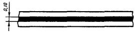
1.1 Purpose: Separation of traffic flows of opposite directions. Designation of traffic lanes. Marking the boundaries of sections of the carriageway to which entry is prohibited. Marking the boundaries of parking lots Vehicle
Fig.1.1 Shape, color, dimensions of road markings
1.2.1 Purpose: Marking the edge of the carriageway
Fig.1.2.1 Shape, color, dimensions of road markings
1.2.2 Purpose: Marking the edge of the carriageway on two-lane roads
Fig.1.2.2 Shape, color, dimensions of road markings
1.3 Purpose: Separation of traffic flows of opposite directions
Rice. 1.3 Shape, color, dimensions of road markings
1.4 Purpose: Designation of places where it is prohibited to stop vehicles
Rice. 1.4 Shape, color, dimensions of road markings
1.5 Purpose: Separation of traffic flows of opposite directions. Designation of traffic lanes
Rice. 1.5 Shape, color, dimensions of road markings
1.6 Purpose: Designation of approach to solid line longitudinal markings
Rice. 1.6 Shape, color, dimensions of road markings
1.7 Purpose: Designation of traffic lanes within the intersection
Rice. 1.7 Shape, color, dimensions of road markings
1.8 Purpose: Marking the boundary between the acceleration or deceleration lane and the main carriageway lane
Rice. 1.8 Shape, color, dimensions of road markings
1.9 Purpose: Designation of the boundaries of traffic lanes on which reverse regulation is carried out. Separation of traffic flows of opposite directions on roads where reverse regulation is carried out (when reverse traffic lights are turned off)
Rice. 1.9 Shape, color, dimensions of road markings
1.10 Purpose: Designation of places where parking of vehicles is prohibited
Rice. 1.10 Shape, color, dimensions of road markings
1.11 Purpose: separation of traffic flows of opposite or passing directions in places where it is necessary to limit maneuvering on the roadway. Designation of places where it is necessary to allow traffic only from the side of the broken line (in places of a U-turn, entry and exit from parking areas, gas stations, stopping points of route vehicles, etc.)
Rice. 1.11 Shape, color, dimensions of road markings
1.12 Purpose: Designation of the stopping place of vehicles - stop line
Rice. 1.12 Shape, color, dimensions of road markings
1.13 Purpose: Designation of a place where the driver must give way
Fig. 1.13 Shape, color, dimensions of road markings
1.14.1 Purpose: Designation pedestrian crossing at 6.00 greater than or equal to P greater than or equal to 4.00
Rice. 1.14.1 Shape, color, dimensions of road markings
1.14.2 Purpose: Designation of a pedestrian crossing at P > 6.00 (see Figure B.1)
Fig.1.14.2 Shape, color, dimensions of road markings
1.15 Purpose: Marking a crossing for cyclists
Rice. 1.15 Shape, color, dimensions of road markings
1.16.1 Purpose: Designation of islands separating traffic flows of opposite directions
Fig.1.16.1 Shape, color, dimensions of road markings
1.16.2 Purpose: Designation of islands separating traffic flows in one direction
Rice. 1.16.2 Shape, color, dimensions of road markings
1.16.3 Purpose: Designation of islands at the confluence of traffic flows
Rice. 1.16.3 Shape, color, dimensions of road markings
1.17 Purpose: Designation of stops of route vehicles and taxi ranks
Rice. 1.17 Shape, color, dimensions of road markings
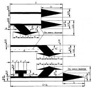
1.18 Purpose: Designation of traffic directions along the lanes (see Figure B.2)
Rice. 1.18 Shape, color, dimensions of road markings
1.19 Purpose: Designation of approach to the narrowing of the carriageway or to a solid line of longitudinal markings 1.1 (see Figure B.3)
Rice. 1.19 Shape, color, dimensions of road markings
1.20 Purpose: Marking the approach to the transverse marking line 1.13 (see Figure B.4)
Rice. 1.20 Shape, color, dimensions of road markings
1.21 Purpose: Marking the approach to the transverse marking line 1.12 (see Figure B.5)
Rice. 1.21 Shape, color, dimensions of road markings
1.22 Purpose: Designation of the road number (see Figure B.6 - B.8)
Rice. 1.22 Shape, color, dimensions of road markings
1.23 Purpose: Designation of a lane of a carriageway intended exclusively for the movement of route vehicles (buses, trolleybuses) (see Figure B.9)
Rice. 1.23 Shape, color, dimensions of road markings
1.24.1 Purpose: Duplication of warning road signs*
Rice. 1.24.1 Shape, color, dimensions of road markings
1.24.2 Purpose: Duplication of prohibition road signs
Rice. 1.24.2 Shape, color, dimensions of road markings
1.24.3 Purpose: Duplication road sign"Disabled"
Rice. 1.24.3 Shape, color, dimensions of road markings
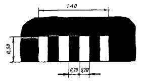
1.25 Purpose: Designation of artificial irregularities
Rice. 1.25 Shape, color, dimensions of road markings
Table A.2
2.1.1 - 2.1.3 Purpose: Designation vertical surfaces road structures (supports of bridges, overpasses, end parts of parapets, etc.):
2.1.1 - to the left of the carriageway;
2.1.2 - on the roadway;
2.1.3 - to the right of the carriageway of the given direction of movement
Rice. 2.1.1 - 2.1.3 Form, color, dimensions of road markings
2.2 Purpose: Designation of the lower edge of the span of overpasses, bridges, tunnels
Rice. 2.2 Shape, color, dimensions of road markings
2.3 Purpose: Designation of round bollards on safety islands
Rice. 2.3 Shape, color, dimensions of road markings
2.4 Purpose: Designation of signal posts, gouges, supports of cable fences, etc.
Rice. 2.4 Shape, color, dimensions of road markings
2.5 Purpose: Designation of side surfaces of road barriers in hazardous areas
Rice. 2.5 Shape, color, dimensions of road markings
2.6 Purpose: Designation of side surfaces of road barriers
Rice. 2.6 Shape, color, dimensions of road markings
2.7 Purpose: Designation of a curb in hazardous areas and side surfaces of elevated safety islands
Rice. 2.7 Shape, color, dimensions of road markings
<*>Images of symbols of signs must correspond to those given in GOST 10807, enlarged to the required size.
Annex B
(mandatory)
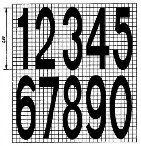
SHAPE AND DIMENSIONS OF ARROWS, LETTERS AND NUMBERS (IN METERS)
Rice. B.1. The shape and size of arrows, letters and numbers (in meters)
Dimensions in meters
Rice. B.2. The shape and size of arrows, letters and numbers (in meters)
Rice. B.3. The shape and size of arrows, letters and numbers (in meters)
Rice. B.4. The shape and size of arrows, letters and numbers (in meters)
Rice. B.5. The shape and size of arrows, letters and numbers (in meters)
Rice. B.6. The shape and size of arrows, letters and numbers (in meters)
Rice. B.7. The shape and size of arrows, letters and numbers (in meters)
Rice. B.8. The shape and size of arrows, letters and numbers (in meters)
Rice. B.9. The shape and size of arrows, letters and numbers (in meters)
Annex B
(mandatory)
TECHNICAL REQUIREMENTS FOR MARKING
Rice. IN 1. Color Area Plot for Road Markings (CIE, 1931)
Table B.1
| Color | Coordinate notation | Coordinates corner points color areas of road markings | |||
| 1 | 2 | 3 | 4 | ||
| White | X | 0,355 | 0,305 | 0,285 | 0,335 |
| at | 0,355 | 0,305 | 0,325 | 0,375 | |
| Yellow | X | 0,443 | 0,545 | 0,465 | 0,389 |
| at | 0,399 | 0,455 | 0,535 | 0,431 | |
| Orange | X | 0,506 | 0,570 | 0,610 | 0,585 |
| at | 0,404 | 0,429 | 0,390 | 0,375 | |
| The black | X | 0,260 | 0,345 | 0,385 | 0,300 |
| at | 0,310 | 0,395 | 0,355 | 0,270 | |
Table B.2
| Color | Coating type | Road characteristic | Road marking luminance coefficient b_v,%, not less than |
| White | asphalt concrete | 60 | |
| 45 | |||
| 30 | |||
| Not standardized | |||
| cement concrete | Roads of category I, main streets of continuous traffic | 60 | |
| Roads II category, main streets | 50 | ||
| Category III roads, local streets | 40 | ||
| Roads IV category, local driveways | Not standardized | ||
| Yellow | Asphalt concrete or cement concrete | Roads of category I, main streets of continuous traffic | 40 |
| Roads II category, main streets | 30 | ||
| Category III roads, local streets | 20 | ||
| Roads IV category, local driveways | Not standardized | ||
| Orange | Roads of category I, main streets of continuous traffic | 30 | |
| Roads II category, main streets | 20 | ||
| Category III roads, local streets | 15 | ||
| Roads IV category, local driveways | Not standardized |
Note - For vertical black markings, the value of the luminance coefficient is not standardized.
Table B.3
| Color | Road characteristic | Coefficient of light reflection of road markings for dark conditions R_L with dry coating, mk x lux (-1) x m (-2), not less than |
| White | Roads of category I, main streets of continuous traffic | 300 |
| Roads II category, main streets | 200 | |
| Category III roads, local streets | 100 | |
| Roads IV category, local driveways | Not standardized | |
| Yellow | Roads of category I, main streets of continuous traffic | 200 |
| Roads II category, main streets | 150 | |
| Category III roads, local streets | 80 | |
| Roads IV category, local driveways | Not standardized | |
| Orange | Roads of category I, main streets of continuous traffic | 150 |
| Roads II category, main streets | 100 | |
| Category III roads, local streets | 50 | |
| Roads IV category, local driveways | Not standardized |
Note - For vertical black markings, the value of the coefficient of retroreflection is not standardized.
Note - For vertical black markings, the value of the coefficient of retroreflection is not standardized.
Annex D
(mandatory)
METHODS OF CONTROL OF ROAD MARKINGS
D.1 Method for measuring the chromaticity coordinates and the luminance coefficient of road markings
D.1.1 The chromaticity coordinates x and y and the luminance factor b_v of the markup are measured with the spectral distribution of radiation from a standard light source D65 according to GOST 7721.
D.1.2 The measurement is carried out with a geometry of 45°/0°, when the light source 3 is located at an angle of 45°, and the photodetector measuring device 1 - perpendicular to the marking surface 2 (Figure D.1).
D.1.3 The surface area of the road markings on which the measurement is carried out must be at least 5 cm2.
D.1.4. Measurements must be carried out on at least three samples. The final measurement result is the average value.
D.1.5 Using a measuring device, the X, Y, Z color coordinates of the road marking sample under study are determined and the color coordinates are calculated using the formulas:
| X+Y+Z |
The luminance factor b_v of the road marking is determined by the Y color coordinate. It is numerically equal to the Y color coordinate expressed as a percentage.
It is possible to directly measure the color coordinates with a colorimeter.
D.2 Method for measuring the coefficient of retroreflection for the conditions of the dark time of the day when illuminated by the headlights of a car and a dry coating
D.2.1 The measurement conditions should simulate the visibility of the marking from the car when it is illuminated by headlights at a distance of 30 m, while the level of the driver's eyes above the road surface should be equal to 1.2 m.
D.2.2 Light reflectance coefficient of the marking R_L, mcd x lux (-1) x m (-2), is calculated by the formula
| R_L = L/E_L | , | (D.3) |
where L is the brightness of the measured surface of the road marking sample under the conditions of illumination and observation shown in Figure D.2, mcd x m(-2);
E_L - illumination of the measured surface of the road marking sample in a plane perpendicular to the direction of the incident light, lx.
D.2.3 Photodetector and light source must be in the same plane perpendicular to the marking surface. The viewing angle alpha is 0.95°.
The angle between the lighting direction and the road marking surface epsilon is 1.34° (Figure D.2)
D.2.4 When measuring, a type A directional light source [T_tsv = (2856+-50) K] should be used.
D.2.5 Aperture measuring devices should not exceed 0.33°.
D.2.6 The measured surface of the road markings must be at least 50 cm2. The entire measurement surface of the road markings must have uniform illumination.
D.3 Method for measuring the coefficient of retroreflection for the conditions of the dark time of the day when illuminated by the headlights of a car and a wet coating
D.3.1 The procedure for measuring the coefficient of retroreflection of the marking is similar to that described in Section D.2.
D.3.2 When carrying out measurements in dry weather, it is necessary to pour from a height of 0.5 m onto the road surface a horizontal section in the measurement zone of about 10 l clean water. After 1 min, the measurement of the values of L and E must be carried out to calculate the value of R_L.
D.4 Method for measuring the coefficient of retroreflection for the conditions of the dark time of the day when illuminated by the headlights of a car and rain
D.4.1 The method for measuring the retroreflection coefficient is similar to that described in section D.3.
D.4.2 When taking measurements in dry weather, it is necessary to simulate rain without fog and evaporation with an intensity of (20+-2) mm/h on a surface twice as wide as the markings, but not less than 0, using a special sprinkling installation (Figure D.3), 3 m and 25% longer than the measured marking surface.
D.4.3 Measurement of the values L and E to calculate the value R_L should be carried out 5 minutes after the start of the rain simulation.
D. 5 Method for measuring the coefficient of adhesion of a wheel with road markings
D.5.1 The adhesion coefficient should be measured with the PKRS-2, PPK-MADI-VNIIBD or other instruments whose readings are reduced to those of PKRS-2.
D.5.2 The measured surface of the road markings must be moistened and, if necessary, pre-cleaned.
D.5.3 The measurement must be repeated at least five times. When the measured values of the friction coefficient do not differ from each other by more than 0.03, the average is calculated from the measurement results, which will be the desired value. Otherwise, the measurement should be repeated until the three values obtained differ by more than 0.03.
Download document
GOST R 51256-99
STATE STANDARD OF THE RUSSIAN FEDERATION
TECHNICAL MEANS
TRAFFIC ORGANIZATIONS
1. DESIGNED State enterprise"ROSDORNII" (SE "ROSDORNII") together with the Research Center of the State Inspectorate for Road Safety (SIC GIBDD) of the Ministry of Internal Affairs of Russia.
INTRODUCED by the Technical Committee for Standardization TK 278 "Road Safety"
2. ADOPTED AND PUT INTO EFFECT by the decision of the State Committee Russian Federation on standardization and metrology dated March 30, 1999 No. 103
3. The standard complies with the requirements of the Convention on Road Signs and Signals (Vienna 1968), taking into account Amendment 1 (1995) and the Protocol on Road Markings (1973) to the European Agreement (1971), supplementing this Convention.
4. INTRODUCED FOR THE FIRST TIME
GOST 9.403-80 Paint and varnish coatings. Test methods for resistance to static effects of liquids.
GOST 7721-89 Light sources for color measurements. Types. Technical requirements. Marking.
GOST 10807-78 Road signs. General specifications.
GOST 19007-73 Paintwork materials. Method for determining the time and degree of drying.
GOST 23457-86 Technical means of traffic management. Application rules.
GOST R 50970-96 Technical means of traffic management. Road signal bollards. General technical requirements. Application rules.
GOST R 50971-96 Technical means of traffic management. Road reflectors. General technical requirements. Application rules.
3. Types and basic parameters
3.1 Lines, inscriptions and other designations used independently, in combination with road signs or traffic lights, on the carriageway of roads with an improved surface, curbs, elements of road structures and road conditions should be considered markings.
3.2 There are two marking groups horizontal and vertical. Each type of markup is assigned a number consisting of numbers, meaning the first number is the number of the group to which the markup belongs (1 - horizontal, 2 - vertical), the second is the serial number of the markup in the group, the third is the type of markup.
3.3 The numbers, shape, color, dimensions and purpose of each type of marking are given in Appendix A (Tables A1 and A2). Dimensions of arrows, letters and numbers are given in Appendix B (Figures B1 - B9).
3.4 Horizontal markings may be permanent or temporary. The functions of temporary road markings are limited to the duration of road works or events that require its introduction.
Temporary road markings, except for 1.4, 1.10, 1.17, must be orange in color and made with materials that allow them to be removed quickly. When applying it, the removal of permanent markings is not necessary.
3.5 Rules for the use of road marking lines are given in GOST 23457.
4. General technical requirements
4.1 Marking can be done with various materials (paint, thermoplastic, cold plastic, polymeric tapes, piece molds, reflectors, etc.) that meet the following technical requirements.
4.2 When drawing marking lines, their deviation from the design position should not exceed 5 cm.
The deviation of the dimensions of the marking lines from those established by this standard should not exceed:
1 cm - along the width of the line;
5 cm - along the length of strokes and breaks.
4.3 The markings should not protrude above the carriageway by more than 6 mm.
Reflectors (reflectors) used for optical orientation of the driver in combination with horizontal marking lines or independently, should not rise more than 15 mm above the carriageway.
4.4 The curing time of markings from plastic marking materials after their application to the coating should not exceed 20 minutes, and drying of paintwork materials to degree 3 according to GOST 19007 - 30 minutes, at a temperature of (20 ± 5) ° C and relative humidity (65 ± 10) %.
4.5 The coefficient of adhesion of horizontal markings in any period of operation should not differ by more than 25% from the coefficient of adhesion of the coating on which this marking is applied.
4.6 Markings made with thermoplastic, cold plastic or other similar materials must have a functional durability of at least one year, and paintwork materials - at least 6 months.
The functional durability of the marking is determined by the period during which the marking meets the requirements of this standard, and on any control section with a length of 50 m, the destruction of the marking made of thermoplastic or other durable materials, except for paints, does not exceed 25%, and the wear of the marking made of paint does not exceed 50% of it. area.
4.7 When marking according to the changed scheme, there should not be visible traces of the old marking.
4.8 Plastic marking materials must be resistant to static exposure to water at a temperature of (20 ± 2) ° C and a saturated sodium chloride solution at a temperature of (0 ± 2) ° C for at least 72 hours, paintwork materials - at least 48 hours.
4.9 Chromaticity coordinates X And at road markings applied to the pavement of the carriageway of roads, determined in the CIE 1931 colorimetric system with a light source D and a measurement geometry of 45 ° / 0 ° (see Figure B.1), should correspond to those specified in Annex B (Table B.1) .
4.10 Marking of roads, except for roads of the 4th category, must be carried out using retroreflective materials.
On road sections that do not have artificial lighting, white markings 2.1 - 2.3 must be made of retroreflective material (except for bollards with internal illumination), and fencing and guiding devices marked with markings 2.4 - 2.6 must have retroreflective elements.
Types of retroreflective elements, their dimensions and installation rules must comply with the requirements of GOST R 50970 and GOST R 50971.
4.11 Retroreflective elements used in conjunction with markings 2.4 - 2.6 or without markings on galvanized surfaces of road barriers, located to the right of the carriageway in the direction of travel, must be red, and to the left - white or yellow.
4.12 The luminance factor of the road markings must correspond to the values specified in Annex B (Table B.2), taking into account the characteristics of the road.
4.13 The coefficient of retroreflection of road markings must correspond to the values specified in Annex B (Tables B.3, B.4), taking into account the characteristics of the road.
4.14 The requirements specified in paragraphs 4.12 and 4.13 for the luminance factor and the coefficient of retroreflection of road markings must be maintained:
For marking from paintwork materials - during the first 3 months. operation;
For markings made of thermoplastic, cold plastic and other durable materials - during the first 6 months. operation.
With further use of road markings, it is allowed to reduce the values of the luminance and retroreflection coefficients given in Appendix B by no more than 25%.
5 General requirements to control methods
5.1 Control of light and color characteristics should be carried out at air temperature (20 ± 2) °C, relative humidity 45 - 80% and atmospheric pressure 84 - 107 kPa (630 - 800 mm Hg).
5.2 Chromaticity coordinate measurements X, at and the coefficient of brightness of the road markings are carried out in accordance with the methodology described in Section D.1 (Appendix D). It is allowed to control the color of road markings by visual comparison with standard samples approved in the prescribed manner, in daylight diffused light and observation in the direction perpendicular to the marking surface.
5.3 Measurement of the coefficient of retroreflection for nighttime conditions when illuminated by the headlights of a car and a dry coating is carried out in accordance with the methodology described in section D.2 (Appendix D).
The measurement of the retroreflection coefficient for the conditions of the dark time of the day when illuminated by the headlights of a car for wet markings and in the rain is carried out in accordance with the methods described in sections D.3 and D.4 (Appendix D).
5.4 Measuring the adhesion coefficient of road markings is carried out in accordance with the methodology described in Section D.5 (Appendix D).
5.5 Measurement of the curing time of the marking after its application to the coating is carried out in accordance with GOST 19007.
5.6 Test marking for resistance to static effects of water and saturated sodium chloride solution is carried out in accordance with GOST 9.403
Annex A
(mandatory)
Shape, color, dimensions of road markings
Table A.1
|
Shape, color, dimensions in m |
Purpose |
||
|
|
Designation of traffic lanes. Marking the boundaries of sections of the carriageway to which entry is prohibited. Marking the boundaries of parking places for vehicles |
||
|
|
Roadway edge marking |
||
|
v? 60 km/h, l 1 = 1,00 l 2 = 2,00; v > 60 km/h, l 1 = 2,00, l 2 = 4,00; l 1:l 2 = 1:2. v - movement speed* |
Marking the edge of the carriageway on two-lane roads |
||
|
|
Separation of traffic flows in opposite directions |
||
|
|
Designation of places where it is prohibited to stop vehicles |
||
|
v? 60 km/h, l 1 = 1,00 - 3,00, l 2 = 3,00 - 9,00; v > 60 km/h, l 1 = 3,00 - 4,00, l 2 = 9,00 - 12,00. l 1:l 2 = 1:3 |
Separation of traffic flows of opposite directions. Designation of traffic lanes |
||
|
v? 60 km/h, l 1 = 3,00 - 6,00, l 2 = 1,00 - 2,00; v > 60 km/h, l 1 = 6,00 - 9,00, l 2 = 2,00 - 3,00. l 1:l 2 = 3:1 |
Designation of approach to a solid line of longitudinal markings |
||
|
|
Designation of traffic lanes within the intersection |
||
|
P = 0.4 - on highways P = 0.2 - on other roads |
Marking the boundary between the acceleration or deceleration lane and the main lane of the carriageway |
||
|
v? 60 km/h, l 1 = 3,00 - 6,00, l 2 = 1,00 - 2,00; v > 60 km/h, l 1 = 6,00 - 9,00, l 2 = 2,00 - 3,00. l 1:l 2 = 3:1 |
Marking the boundaries of traffic lanes on which you carry out reverse regulation. Separation of traffic flows of opposite directions on roads where reverse regulation is carried out (when reverse traffic lights are turned off) |
||
|
|
Designation of places where parking of vehicles is prohibited |
||
|
At U-turn points, entry and exit from the adjacent territory l 1 = 0,9, l 2 = 0,3 v? 60 km/h, l 1 = 3,00 - 6,00, l 2 = 1,00 - 2,00; v > 60 km/h, l 1 = 6,00 - 9,00, l 2 = 2,00 - 3,00; l 1:l 2 = 3:1 |
Separation of traffic flows of opposite or passing directions in places where it is necessary to limit maneuvering on the roadway. Designation of places where it is necessary to allow traffic only from the side of the broken line (in places of a U-turn, entry and exit from parking areas, gas stations, stopping points of route vehicles, etc.) |
||
|
|
Designation of the stopping place of vehicles - stop line |
||
|
|
Designation of the place where the driver must give way |
||
|
|
Designation of a pedestrian crossing at 6.00? R? 4.00 |
||
|
|
Designation of a pedestrian crossing at P > 6.00 (see Figure B.1) |
||
|
|
Crossing sign for cyclists |
||
|
|
Designation of islands separating traffic flows of opposite directions |
||
|
|
Designation of islands separating traffic flows in the same direction |
||
|
|
Designation of islands at the confluence of traffic flows |
||
|
|
Designation of stops of route vehicles and taxi ranks |
||
|
|
Designation of traffic directions along the lanes (see Figure B.2) |
||
|
|
Approach to a narrowing of the carriageway or to a solid line of longitudinal markings 1.1 (see Figure B.3) |
||
|
|
Marking the approach to the transverse marking line 1.13 (see Figure B.4) |
||
|
|
Marking the approach to the transverse marking line 1.12 (see Figure B.5) |
||
|
|
Road number designation (see figures B.6 - B.8) |
||
|
|
Designation of the lane of the carriageway intended exclusively for the movement of route vehicles (buses, trolleybuses) (see Figure B.9) |
||
|
|
Duplication of warning road signs* |
||
|
* Images of symbols of signs must comply with those given in GOST 10807, enlarged to the required size |
|||
|
|
Duplicate prohibition road signs |
||
|
|
Duplication of the road sign "Disabled" |
||
|
|
Designation of artificial bumps |
||
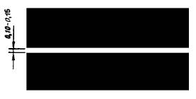
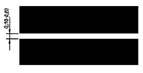
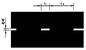
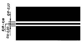
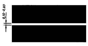
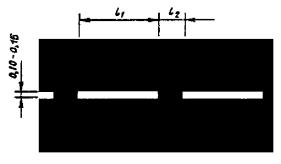
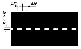
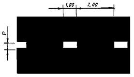
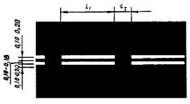
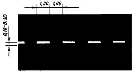
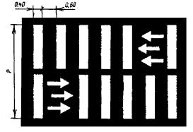
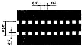
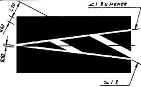
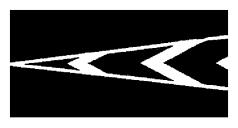
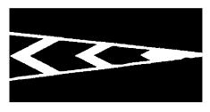
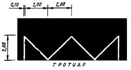
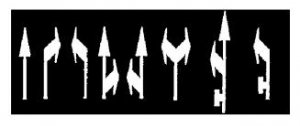
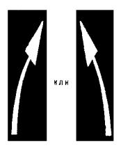

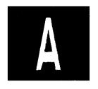
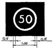
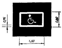
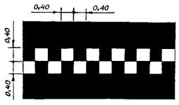
Table A.2
|
Shape, color, dimensions in m |
Purpose |
|
|
H< 2,00, В? 0,30, а = 0,10; H< 2,00, В >0.30, a = 0.15; H? 2.00, B > 0.30, a = 0.20 |
Designation of vertical surfaces of road structures (supports of bridges, overpasses, end parts of parapets, etc.). 2.1.1 - to the left of the carriageway; 2.1.2 - on the roadway; 2.1.3 - to the right of the carriageway of the given direction of movement |
|
|
|
Designation of the lower edge of the span of overpasses, bridges, tunnels |
|
|
IN? 0.30, a = 0.10; B > 0.30, a = 0.15 |
Designation of round bollards on safety islands |
|
|
|
Designation of signal posts, gouges, supports of cable fences, etc. |
|
|
|
Designation of side surfaces of road barriers in hazardous areas |
|
|
|
Designation of side surfaces of road barriers |
|
|
l 1 = 0,20 - 1,00; l 2 = 0,40 - 2,00; l 1:l 2 = 1:2 |
Curb designation in hazardous areas and side surfaces of elevated safety islands |
Annex B
(mandatory)
The shape and size of arrows, letters and numbers (in meters)
Figure B.1
Dimensions in meters
In parentheses are the dimensions for V ? 60 km/h
Figure B.5
V > 60 km/h
Figure B.9
Annex B
(mandatory)
Technical requirements for markup
Table B.1
Table B.2
Note - For vertical black markings, the value of the luminance coefficient is not standardized.
Figure B.1 Plot of color areas for road markings (CIE, 1931)
Table B.3
Table B.4
Note - For vertical black markings, the value of the coefficient of retroreflection is not standardized.
Annex D
(mandatory)
Road marking control methods
D.1 Method for measuring the chromaticity coordinates and the luminance coefficient of road markings
D.1.1 Chromaticity coordinates X And at and the brightness coefficient b v of the marking is measured with the spectral distribution of the radiation of a standard light source D65 according to GOST 7721.
D.1.2 The measurement is carried out with a geometry of 45°/0°, when the light source 3 is located at an angle of 45°, and the photodetector of the measuring device 1 is perpendicular to the marking surface 2 (Figure D.1).
D.1.3 The surface area of the road markings on which the measurement is carried out must be at least 5 cm 2.
D.1.4 Measurements should be carried out on at least three samples. The final measurement result is the average value.
D.1.5 Using a measuring device, the X, Y, Z color coordinates of the road marking sample under study are determined and the color coordinates are calculated using the formulas:
![]() (D.1)
(D.1)
![]() (D.2)
(D.2)
The brightness coefficient b v , road markings is determined by the Y color coordinate. It is numerically equal to the Y color coordinate, expressed as a percentage.
It is possible to directly measure the color coordinates with a colorimeter.
D.2 Method for measuring the coefficient of retroreflectivity of the markings for the conditions of the dark time of the day when illuminated by the headlights of a car and dry coating
D.2.1 The measurement conditions should simulate the visibility of the marking from the car when it is illuminated by headlights at a distance of 30 m, while the level of the driver's eyes above the road surface should be equal to 1.2 m.
D.2.2 Coefficient of retroreflective marking R L , mcd? lx -1 ? m -2, calculated by the formula:
R L = L/E ^ , (D.3)
where L is the brightness of the measured surface of the road marking sample under the lighting and observation conditions shown in Figure D.2, mcd? m -2,
E ^ - illumination of the measured surface of the road marking sample in the plane perpendicular to the direction of the incident light, lx.
D.2.3 Photodetector and light source must be in the same plane , perpendicular to the marking surface. The viewing angle a is 0.95°.
Angle between lighting direction and road marking surface? is 1.34° (Figure D.2).
D.2.4 During measurements, a type A directional light source [T CV = (2856 ± 50) K] should be used.
D.2.5 The aperture of measuring devices should not exceed 0.33°.
D.2.6 The measured surface of the road markings must be at least 50 cm 2 . The entire measurement surface of the road markings must have uniform illumination.
D.3 Method for measuring the coefficient of retroreflection of the markings for the conditions of the dark time of the day when illuminated by the headlights of a car and a wet surface
D.3.1 The procedure for measuring the coefficient of retroreflection of the marking is similar to that described in Section D.2.
D.3.2 When carrying out measurements in dry weather, it is necessary to pour about 10 liters of clean water onto the road surface of a horizontal section in the measurement zone from a height of 0.5 m. After 1 min, the measurement of the values of L and E should be carried out to calculate the value of R L .
D.4 Method for measuring the coefficient of retroreflection for the conditions of the dark time of the day when illuminated by the headlights of a car and rain
D.4.1 The method for measuring the retroreflection coefficient is similar to that described in section D.3.
D.4.2 When taking measurements in dry weather, it is necessary to simulate rain without fog and evaporation with an intensity of 20 ± 2 mm/h on a surface twice as wide as the markings, but not less than 0.3 m, using a special sprinkling installation (Figure D.3) and 25% longer than the measured marking surface.
D.4.3 Measurement of the values L and E to calculate the value of RL should be carried out 5 minutes after the start of the rain simulation.
D.5 Method for measuring the coefficient of adhesion of a wheel with road markings
D.5.1 The adhesion coefficient should be measured with the PKRS-2, PPK-MADI-VNIIBD or other instruments whose readings are reduced to those of PKRS-2.
D.5.2 The measured surface of the road markings must be moistened and, if necessary, pre-cleaned.
1 - photodetector, 2 - light source, 3 - marking surface b = 87.7°, ? = 0.95°, e = 1.34°
Figure D.2 - Scheme for measuring the coefficient of retroreflection of road markings for dark conditions when illuminated by headlights of a car and dry pavement
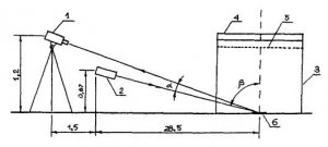
1 - brightness meter, 2 - light source, 3 - sprinkler, 4 - hose, 5 - grid, 6 - road markings (Distances in meters)
Figure D.3 - Scheme for measuring the coefficient of retroreflection of road markings for the conditions of the dark time of the day when illuminated by the headlights of a car and rain
Keywords: road markings, line types, dimensions, technical requirements, control methods
Road marking is divided into two types:
- The horizontal line is drawing lines, inscriptions, arrows and other designations on the road;
- Vertical markings are a combination of black and white stripes that are applied to carriageway, as well as on road structures, so that drivers are informed about the dimensions of these structures.
Road marking dimensions
As for horizontal markings, according to the state standard of the Russian Federation, adopted in 1999, its external limits must be within the normal range of the standard.
Road marking dimensions detailed in state standard about technical means . Road markings, namely arrows, letters and numbers are given in the appendix of point B (in figures B.1 - B.9).
Road marking width
The width of the road markings is calculated according to the category of roads. The width of the traffic lanes complies with the building code standard. If the transverse profile elements do not meet the requirements of building codes, then the strip width must be equal to 3.00 meters or more.
It is also allowed to reduce the width of the road markings if this lane is intended for the movement of cars. Marking can be reduced to 2.75 m, however, the restriction of the mode of movement of road transport must be observed.
The width of the strip is determined by the distance between the marking lines that represent its boundaries.
Application of road markings
Cement concrete pavements are painted with a longitudinal marking line, which separates the transport path of passing traffic near the temperature seam on the left side of the movement, and separating the flows of oncoming traffic - on any side of the seam.
As for the color of the coating, it is white (yellow) or orange. This depends on the type of markup - permanent or temporary. Permanent - limited in time of action, it is usually white, sometimes yellow. Second variety pavement- temporary, it is applied to the road on certain time. Temporary markings are colored orange.
The dimensions of the road markings must be made according to the standard - with high quality. Correctly executed marking under any conditions will direct traffic flows and supplement the information of road signs. The presence of road markings not only increases the safety of all participants traffic, but also optimizes the number of cars on the road. And do not forget that while parking a car, road markings play an important role.
We also recommend
 Switching power supply: repair and refinement
 Remote control of light
 Swimming lessons for preschool children
 Notes for the master - home household alarms
 Clock propeller on Atmega8
 Device and relay application examples, how to choose and connect a relay correctly Microcontroller and relay simple switching circuits