Placement of fire detectors. Mounting and installation of fire alarms Placement of fire alarm detectors
Requirements for the placement of fire detectors are given in NPB 88-2001 * “Fire extinguishing and alarm installations. Norms and rules of design». However, this document regulates only the basic options for the placement of detectors for relatively simple cases. In practice, there are often rooms with sloping ceilings, with decorative suspended lattice ceilings, with supply and exhaust ventilation, etc., which must be properly protected, despite the absence of specific instructions in NPB 88-2001*. For all atypical cases, there is a general requirement in clause 3. NPB 110-03 "List of buildings, structures, premises and equipment to be protected automatic settings fire extinguishing and automatic fire alarm systems": "The type of automatic fire extinguishing installation, the method of extinguishing, the type of fire extinguishing agents, the type of equipment for fire automatics installations is determined by the design organization, depending on the technological, structural and space-planning features of the buildings and premises to be protected, taking into account the requirements of the current regulatory and technical documents". NPB 88-2001* also contains general requirements, for example, according to clause 12.19 “placement of point heat and smoke fire detectors should be carried out taking into account air flows in the protected room caused by supply or exhaust ventilation”, however, criteria for optimizing the location of the detectors are not given, it is only stated that “in this case, the distance from the detector to the ventilation hole must be at least 1 m.”
In many complex cases, gross design errors can be avoided by using additional materials, for example, the European standard BS 5839-1:2002 for fire detection and warning systems for buildings, part 1 "Norms and rules for the design, installation and maintenance of systems", where in each section and in each paragraph, the physical processes are first stated, and then the requirements arising from them, which allows you to be confident in the correctness of the chosen solution in a particular case. For example, when arranging automatic fire detectors, it is necessary to take into account the specifics of their operation depending on the type:
“Heat and smoke detectors rely on convection to carry hot gas and smoke from the hearth to the detector. The location and installation spacing of these sensors should be based on the need to limit the time spent on this movement and subject to a sufficient concentration of combustion products at the location of the sensor. Hot gas and smoke will generally be concentrated in the highest parts of the room, so this is where the heat and smoke sensors should be located. Since the smoke and hot gases from the hearth rise up, they are diluted with clean and cold air, which enters the convective jet. Consequently, as the height of the room increases, the size of the hearth increases rapidly, sufficient to activate heat or smoke sensors. To some extent, this effect can be compensated for by using more sensitive sensors. Linear smoke detectors with an optical beam are less sensitive to the effect of a high ceiling than point-type detectors, since with an increase in the smoky space, the length of the beam affected by smoke increases proportionally. In addition, when the ambient air is captured by the convection jet, the gases are cooled. If the ceiling is high enough and the ambient temperature in the upper part of the room is high, the temperature of the flue gas mixture may drop to environment at a level below the ceiling. This is possible if the indoor air temperature increases with altitude, for example, as a result of solar heating, the air at higher levels can be higher than the temperature of the smoke. Then a layer of smoke will form at that level before reaching the ceiling, as if the room had an invisible ceiling at a certain height. This effect is known as stratification - stratification. In this case, both smoke and hot gases will not affect ceiling-mounted sensors, regardless of their sensitivity. It is usually difficult to predict with a sufficiently high degree of certainty the level at which stratification will occur. This will depend on the convective heat output of the source and on the temperature profile within the protected space at the time of the fire, neither of which is known quantitatively. If the sensors are installed at the intended level of stratification, and stratification does not occur or it occurs at more than high level, detection can be dangerously late as the relatively narrow convection jet can bypass the sensors. Eventually, as the hearth expands and more heat is released, the convection jet will overcome the thermal barrier and the ceiling-mounted sensors will be operational, albeit at a later stage of the fire than if no stratification had occurred. (However, a larger focus is usually detected if the ceiling height is higher.) Thus, in a high room where stratification is likely, although additional sensors at lower levels may be used in the hope of detecting a stratified layer, sensors mounted on ceiling. Since the hot gas jet is relatively narrow, the radius of the control zone of additional detectors must be reduced. While the above considerations apply for normal area protection, local areas can be protected by additional fire detectors. For example, systems with thermal line sensors may be particularly suitable for protecting power plant components or cable networks. When used for this purpose, the sensor should be installed as close as possible to the place where fire or overheating could occur, it should be located above or in thermal contact with the installation to be protected.
The effectiveness of an automatic fire detection system will be affected by obstructions between heat or smoke detectors and combustion products. It is important that heat and smoke sensors are not installed too close to obstructions to the flow of hot gases and smoke to the sensor. Near the wall-ceiling junction there is a "dead space" where heat or smoke detection will not be effective. Since the hot gas and smoke flow horizontally parallel to the ceiling, there is similarly a stagnant layer near the ceiling; this precludes installation with the sensing element of the heat or smoke detector flush with the ceiling. This limitation may be less important in the case of an aspiration system, since this system actively draws air samples from a moving layer of smoke and hot gases. When installing heat and smoke sensors, the possible structure of the air flows in the room must be considered. Air conditioning and ventilation systems with a high level of air exchange can adversely affect the ability of the sensors by creating an influx to them fresh air and the outflow of heated air, smoke and gases from combustion or liquefying smoke and hot gases from the hearth. Smoke detectors can be installed to monitor smoke in ventilation ducts. Basically, such sensors should help prevent the spread of smoke. ventilation system, any recirculation must be stopped in case of fire. These detectors can be connected to a fire alarm system, but if the smoke detectors are of normal sensitivity, they cannot be a satisfactory means of detecting a fire in the area from which the air is drawn, since the smoke is diluted by the extracted clean air ... ".
Two basic principles follow from the above physical model, which are taken into account when placing smoke and heat fire detectors:
- in the case of flat ceilings, in the absence of interference and obstacles, smoke and heat detectors protect the area in the form of a circle in a horizontal plane;
– it is necessary to regulate the minimum and maximum distance of the detectors from the ceiling.
Fig.1. The simplest layout of the smoke and heat detector
According to BS 5839-1:2002, the protection radius for smoke detectors is 7.5 m, for heat detectors it is 5.3 m in horizontal projection. Thus, it is easy to determine the placement of detectors in a room of any shape: the distance from any point in the room to the nearest smoke MT in horizontal projection should be no more than 7.5 m, from the thermal one - no more than 5.3 m. These radii of the protected area determine somewhat larger distances between detectors when arranged on a square grid (Fig. 1) compared to the requirements of NPB 88-2001*. Significant savings in the number of detectors (approximately 1.3 times) are achieved in large rooms when using the placement of detectors on a triangular grid (Fig. 2).

Fig.2. Arrangement of detectors in large rooms
At present, in practice, these provisions can only be applied when using aspiration detectors. In the Recommendations of the Federal State Institution VNIIPO EMERCOM of Russia on the design of systems fire alarm using aspirating smoke detectors of the LASD and ASD series, it is stated that “when protecting rooms of arbitrary shape, the maximum distances between air sampling openings and walls are determined based on the fact that the area protected by each air sampling opening has the shape of a circle with a radius of 6.36 m (Fig. 3).

Fig.3. Each hole protects a circle with a radius of 6.36 m
Distance to overlap
According to the British standard BS5839, fire detectors must be installed on the ceiling so that their sensing elements are located below the ceiling within:
1) 25 mm - 600 mm for smoke detectors;
2) 25 mm - 150 mm for thermal sensors.
A layer of clean air remains directly at the ceiling, which determines the minimum distance from the sensing element of the smoke and heat detector to the ceiling, equal to 25 mm. For the same reason, flush mounting of detectors is prohibited. In NPB 88-2001 *, a similar requirement is indicated so far only for a linear smoke fire detector, clause 12.29. “the optical axis passed at a distance of at least 0.1 m from the ceiling level” and for linear thermal fire detectors, clause 12.37: “the distance from the detector to the ceiling must be at least 15 mm.” According to NPB 88-2001 * clause 12.18 * for all point fire detectors “when the detectors are suspended on a cable, their stable position and orientation in space must be ensured. In this case, the distance from the ceiling to the lower point of the detector should be no more than 0.3 m. BS5839 specifies different maximum ceiling distances for smoke and heat detectors. Smoke detectors provide early fire detection at the stage of smoldering materials, and it is possible to place them at a distance of about 300 mm from the ceiling even in the absence of a stratification effect. Unlike smoke detectors, heat detectors do not detect smoldering fires, and at the open fire stage there is a significant increase in temperature, respectively, there is no stratification effect and an increase in the distance between the ceiling and the temperature-sensitive element by more than 150 mm will lead to an unacceptably late fire detection, i.e. .make them practically inoperable.
Perforated ceilings
Airports, major shopping malls etc. decorative grilles are often used to cover ducts and cables placed under the ceiling. For example, ceilings of the "Gree" type. How should fire detectors be installed in this case? BS 5839-1:2002 specifies that sensors installed on the main ceiling can be used to protect the area below a perforated false ceiling if the following conditions are simultaneously met:
1) the perforation area is more than 40% of any 1m x 1m ceiling section;
2) the minimum size of each perforation in any section is at least 10 mm;
3) the thickness of the false ceiling is not more than three times the minimum size of each perforation cell.
In all other cases, sensors should be installed below the false ceiling, and if overhead protection is required, additional sensors should be installed on the main ceiling in the overhead space.
When the above conditions are met, the room is practically not divided into two spaces, the smoke passes through the perforation of the false ceiling and is detected by detectors installed on the ceiling. These conditions are satisfied with a large margin for the Grilyato-type ceiling; for greater persuasiveness, it is recommended to consider it as decorative grille, which practically does not create obstacles for the spread of smoke.
Sloped floors
The absence of the concept of an inclined, non-horizontal overlap in our standards can lead to gross design errors. The maximum allowable distance from the sensitive element of the detector to the overlap determines the criterion for assessing the horizontality of the overlap, and without using any values of the angle of inclination. If the height difference of the ceiling when using smoke detectors does not exceed 600 mm, then the smoke accumulates in the upper part of the room and the ceiling is considered to be horizontal, regardless of the area of the room. Similarly for heat detectors, if the height difference does not exceed 150 mm, the ceiling is also considered to be horizontal, regardless of the size of the room. At large height differences, smoke with warm air flows up the slope in the direction of the ridge, and the upper part of the volume is filled. In this case, the first row of fire detectors is installed along the ridge, and the remaining rows are parallel along the slopes of the first. It is possible to place detectors at a lower level, while the sensing elements of the smoke detector must be located at least 600 mm from the top of the ceiling, and thermal elements at least 150 mm (Fig. 4).

Fig.4. Room protection with ramps at various angles BS 5839-1:2002
In addition, the sloping section of the overlap tends to increase the rate of rise of the smoke and warm air flow towards the top, thus reducing the delay time before the detector is triggered. Accordingly, in BS 5839-1:2002 it is allowed to increase the distance between the detectors in top row: for each degree of slope angle, it is allowed to increase the distance between the detectors by 1%, but a maximum of 25%. If the roof slopes have different angles of inclination, then the distance between the detectors installed along the ridge is selected based on the smaller value determined by the smaller angle of inclination (Fig. 4). AT this example between the detectors along the ridge it is allowed to increase by 18%, i.e. up to 12.39 m. The rest of the detectors are installed based on the standard value of the radius of the protected area, equal to 7.5 m in horizontal projection. At the same time, it is recommended to apply Special attention when determining the location of the next rows of detectors, in order to avoid gaps between the circles of detectors of different rows and different radii.
Of course, we cannot use these nuances in practice, but the criterion of sloping overlap is quite applicable. According to NPB 88-2001 * p. 12.18 *, already mentioned above, for all point fire detectors "<...>the distance from the ceiling to the lower point of the detector should be no more than 0.3 m. Thus, in a room of 9 x 9 m with a height difference of about 0.6 m, it is possible to install the detector in the center of the room, and with a larger height difference, it is recommended to place it on a higher part of the ceiling. In this case, the requirement specified in clause 12.18 * should be met: "When installing point fire detectors under the ceiling, they should be placed at a distance of at least 0.1 m from the walls." Note that in BS 5839-1:2002 this distance for horizontal floors is 0.5 m.
Similar to the requirements for point smoke detectors, when installing linear smoke detectors in BS 5839-1:2002, it is necessary to ensure that the distance from the beam to the horizontal overlap is between 25 mm and 600 mm. In a room with a non-horizontal ceiling, i.e. with a ceiling height difference of more than 600 mm, it is necessary to protect the space along the roof ridge. In this case, according to BS 5839-1:2002, the distance between the optical axes of linear detectors can also be increased by 1% for each degree of inclination, up to a maximum value of 25% (Fig. 5).

Fig.5. Protection of a room with a sloping ceiling
In our practice, the distance between the optical axes not only cannot be reduced, but it can hardly be measured in horizontal projection, since Table 6 of NPB 88-2001 * indicates the maximum distances directly between the optical axes of the detectors, without taking into account the possibility of their placement on an inclined overlap.

Fig.6. Premises protection at an average level
Where linear smoke detectors cannot be installed below the ceiling, such as in glass domed atriums, BS 5839-1:2002 allows them to be placed below 600 mm from the ceiling. However, with such an arrangement of detectors, the protected area is significantly reduced and amounts to 12.5% of the installation height in each direction from the optical axis (Fig. 6.) height. So, for example, when installed at a height of 4 m, for reliable detection of the source, the distance between the optical axes should be no more than 1 m, when installed at a height of 20 m - no more than 5 m, respectively.
Floors with beams
In large industrial premises usually on the floor there are beams of considerable height. The arrangement of the detectors in this case must be carried out in accordance with clause 12.20. NPB 88-2001*: “Point smoke and heat fire detectors should be installed in each compartment of the ceiling with a width of 0.75 m or more, limited building structures(beams, purlins, ribs of slabs, etc.) protruding from the ceiling at a distance of more than 0.4 m. If building structures protrude from the ceiling at a distance of more than 0.4 m, and the compartments they form are less than 0.75 m wide , controlled by fire detectors, the area indicated in tables 5, 8 is reduced by 40%. If there are protruding parts on the ceiling from 0.08 to 0.4 m, the area controlled by fire detectors, indicated in tables 5, 8, is reduced by 25%.
At the same time, it is not indicated on which axes the distance between the detectors should be reduced. The beams prevent the spread of smoke in the transverse direction, and, therefore, it is necessary to reduce the distances in this direction, providing a given reduction in the controlled area. It makes no sense to reduce the distances between the detectors along the beams, since smoke spreads even faster between the beams, since the effect of space limitation appears as in the corridor, where the distances between the detectors can be increased by 1.5 times.

Fig.7. Ceiling with beams, M - distance between detectors
BS 5839-1:2002 discusses two options in more detail: linear beams (fig. 7) and honeycombs (fig. 8).

Fig.8. honeycomb ceiling
The requirements of BS 5839-1:2002 for allowable distances between detectors across beams depending on the height of the ceiling, the height of the beams are given in table 1.
Table 1
For a ceiling in the form of honeycombs, depending on the ratio of the height of the beam and the width of the cell, fire detectors are installed either on the ceiling or on the beam (table 2). Here, the beam height limit of 600 mm appears (unlike our 400 mm), but the relative height of the beam is also taken into account - an additional border, 10% of the height of the room.
table 2
| Ceiling height H (rounded to the nearest integer), m | Beam height D | Maximum distance to the nearest smoke (heat) detector | Detector placement at W | Detector placement at W>4D |
| 6 m or less | Less than 10%H | Like a flat ceiling | On the bottom plane of the beams | On the ceiling |
| Over 6 m | Less than 10% H and 600mm or less | Like a flat ceiling | On the bottom plane of the beams | On the ceiling |
| Over 6 m | Less than 10% H and more than 600mm | Like a flat ceiling | On the bottom plane of the beams | On the ceiling |
| 3 m or less | More than 10% H | 4.5 m (3 m) | On the bottom plane of the beams | On the ceiling |
| 4 m | More than 10% H | 5.5 m (4 m) | On the bottom plane of the beams | On the ceiling |
| 5 m | More than 10% H | 6 m (4.5 m) | On the bottom plane of the beams | On the ceiling |
| >= 6 m | More than 10% H | 6.6 m (5 m) | On the bottom plane of the beams | On the ceiling |
Where, H is the height of the ceiling; W is the cell width; D is the height of the beam.
12. Fire alarm systems
General provisions when choosing types of fire detectors for a protected object
12.1. The choice of the type of point smoke detector is recommended to be made in accordance with its ability to detect various types of smoke, which can be determined according to GOST R 50898.
12.2. Flame fire detectors should be used if an open flame is expected to appear in the control zone in the event of a fire at its initial stage.
12.3. The spectral sensitivity of the flame detector must correspond to the emission spectrum of the flame of combustible materials located in the control zone of the detector.
12.4. Thermal fire detectors should be used if significant heat release is expected in the control zone in the event of a fire at its initial stage.
12.5. Differential and maximum-differential thermal fire detectors should be used to detect a fire source, if there are no temperature drops in the control zone that are not associated with the occurrence of a fire that can cause the operation of these types of fire detectors.
Maximum thermal fire detectorsNot recommended for indoor use
with low temperatures (below 0 o C);
with the storage of material and cultural values.
Note.Except in cases where the use of other detectors is impossible or impractical.
12.6. When choosing thermal fire detectors, it should be taken into account that the response temperature of maximum and maximum differential detectors must be at least 20° From above max. allowable temperature air in the room.
12.7. Gas fire detectors are recommended to be used if in the control zone in the event of a fire at its initial stage, a certain type of gas is expected to be released in concentrations that can cause the detectors to operate. Gas fire detectors should not be used in rooms where, in the absence of a fire, gases may appear in concentrations that cause the detectors to operate.
12.8. In the event that the dominant fire factor is not determined in the control zone, it is recommended to use a combination of fire detectors that respond to various fire factors, or combined fire detectors.
12.9. The choice of types of fire detectors, depending on the purpose of the protected premises and the type of combustible load, is recommended to be made in accordance with Appendix 12.
12.10. Fire detectors should be used in accordance with the requirements of state standards, fire regulationssecurity,technicaldocumentation and taking into account climatic, mechanical, electromagnetic and other influences at their locations.
12.11. Fire detectors designed to issue notifications forAUP control, smoke removal, fire warning, shouldbe resistant to electromagnetic interferencewith a degree of rigidity not lower than the second according to NPB 57-97.
12.12. Smoke detectors powered by a fire alarm loop and having a built-in sound annunciator are recommended to be used for operational, local notification and determining the location of a fire in rooms in which the following conditions are simultaneously met:
The main factor in the occurrence of a fire in the initial stage is the appearance of smoke;
Presence of people is possible in the protected premises.
Such detectors should be included in a unified fire alarm system with the output of alarm notices to the fire alarm control device located in the premises of the duty personnel.
Notes:
1. These detectors are recommended for use in hotels, medical institutions, museum exhibition halls, art galleries, library reading rooms, retail premises, computer centers.
2.Applicationof these detectors does not exclude the equipment of the building with a warning system in accordance with NPB 104.
Requirements for the organization of fire alarm control zones
12.13. It is allowed to equip a control zone with one fire alarm loop with fire detectors that do not have an address, including:
premises located on different floors, with a total area of 300 m 2 or less;
up to ten isolated and adjacent premises, with a total area of not more than 1600 m 2 located on the same floor of the building, while isolated rooms must have access to a common corridor, hall, lobby, etc.;
up to twenty isolated and adjacent rooms, with a total area of not more than 1600 m 2 located on the same floor of the building, while isolated rooms must have access to a common corridor, hall, lobby, etc., if there is a remote light signaling about the operation of fire detectors above the entrance to each controlled room.
12.14. The maximum number and area of premises protected by one ring or radial loop with addressablefire detectors, is determined by the technical capabilities of the receiving and control equipment, the technical characteristics of the detectors included in the loop and does not depend on the location of the premises in the building.
Placement of fire detectors
12.15. The number of automatic fire detectors is determined by the need to detect fires over the entire controlled area of premises (zones), and for flame detectors - and equipment.
12.16. At least two fire detectors should be installed in each protected room.
12.17. It is allowed to install onefire detector if the following conditions are met simultaneously:
a) area of the room more area protected by a fire detector, specified in the technical documentation for it, and not more than the average area indicated in tables 5, 8;
b) automatic monitoring of the fire detector performance is provided, confirming the performance of its functions with the issuance of a malfunction notice to the control panel;
c) identification of a faulty detector by a control panel is provided;
d) a signal from a fire detector does not generate a signal to start the control equipment that turns on automatic fire extinguishing or smoke removal systems or type 5 fire warning systems according to NPB 104.
12.18. Point fire detectors, except for flame detectors, should be installed, as a rule, under the ceiling. If it is impossible to install detectors directly under the ceiling, they can be installed on walls, columns and other load-bearing building structures, as well as mounted on cables.
When installing point fire detectors under the ceiling, they should be placed at a distance of at least 0.1 m from the walls.
When installing point fire detectors on walls, special fittings or fastening on cables, they should be placed at a distance of at least 0.1 m from the walls and at a distance of 0.1 to 0.3 m from the ceiling, including the dimensions of the detector.
When the detectors are suspended on a cable, their stable position and orientation in space must be ensured.
12.19. Placement of point heat and smoke fire detectors should be carried out taking into account the air flows in the protected room caused by supply or exhaust ventilation, while the distance from the detector to the ventilation opening should be at least 1 m.
12.20. Point smoke and heat fire detectors should be installed in each section of the ceiling with a width of 0.75 m or more, limited by building structures (beams, purlins, plate ribs, etc.) protruding from the ceiling at a distance of more than 0.4 m.
If building structures protrude from the ceiling at a distance of more than 0.4 m, and the compartments they form are less than 0.75 m wide, the area controlled by fire detectors, indicated in tables 5, 8, is reduced by 40%.
If there are protruding parts on the ceiling from 0.08 to 0.4 m, the area controlled by fire detectors, indicated in tables 5, 8, is reduced by 25%.
If there are ducts in the controlled room, technological platforms with a width of 0.75 m or more, having a solid structure, spaced along the lower mark from the ceiling at a distance of more than 0.4 m and at least 1.3 m from the floor plane, it is necessary to additionally install under them fire detectors.
12.21. Point smoke and heat fire detectors should be installed in each compartment of the room formed by stacks of materials, racks, equipment and building structures, the upper edges of which are 0.6 m or less from the ceiling.
12.22. When installing point smoke detectors in rooms with a width of less than 3 m or under a raised floor or above a false ceiling and in other spaces with a height of less than 1.7 m, the distance between the detectors indicated in Table 5 can be increased by 1.5 times.
12.23. Fire detectors installed under the raised floor, above the false ceiling, must be addressable, or connected to independent fire alarm loops, and it must be possible to determine their location.The design of the raised floor and false ceiling slabs should provide access to fire detectors for their maintenance.
12.24. Fire detectors should be installed in accordance with the requirements of the technical documentation for this detector.
12.25. In places where there is a danger of mechanical damage to the detector, a protective structure must be provided that does not impair its performance and the effectiveness of fire detection.
12.26. If different types of fire detectors are installed in one control zone,their placement is made in accordance with the requirements of these standards for each type of detector.
In the case of using combined (heat-smoke) fire detectors, they should be installed according to table 8.
12.27. For rooms in which, in accordance with Appendix 12, it is possible to use both smoke and heatfire detectors, their combined use is allowed. In this case, the placement of the detectors is made according to table 8.
Point smoke detectors
12.28. The area controlled by one point smoke detector, as well as the maximum distance between the detectors and the detector and the wall, except for the cases specified in clause 12.20, must be determined according to table 5, but not exceeding the values \u200b\u200bspecified in specifications and passports for detectors.
Table 5
|
Average area controlled one detector, m 2 |
Maximum distance, m |
||
|
between detectors |
from the detector to the wall |
||
|
Up to 3.5 |
Up to 85 |
9,0 |
4,5 |
|
Over 3.5 to 6.0 |
Up to 70 |
8,5 |
4,0 |
|
Over 6.0 to 10.0 |
Up to 65 |
8,0 |
4,0 |
|
St. 10.5 to 12.0 |
Up to 55 |
7,5 |
3,5 |
Linear smoke detectors
12.29. Emitter and receiverlinear smoke detectorshould be installed on walls, partitions, columns and other structures in such a way that their optical axis passes at a distance of at least 0.1 m from the floor level.
12.30. Emitter and receiverof a linear smoke detector should be placed on the building structures of the room in such a way that various objects do not fall into the detection zone of the fire detector during its operation. The distance between the emitter and the receiver is determined by the technical characteristics of the fire detector.
12.31. When monitoring the protected area with two or more linear smoke detectors, the maximum distance between their parallel optical axes, the optical axis and the wall, depending on the installation height of the fire detector units, should be determined from the table6.
Table 6
|
Maximum distance between optical axes of detectors, m |
Maximum distance from the optical axis of the detector to the wall, m |
|
|
Up to 3.5 |
9,0 |
4,5 |
|
Over 3.5 to 6.0 |
8,5 |
4,0 |
|
Over 6.0 to 10.0 |
8,0 |
4,0 |
|
St. 10, 0 to 12.0 |
7,5 |
3,5 |
12.32. In rooms with a height of over 12 and up to 18 m, detectors should, as a rule, be installed in two tiers, in accordance with Table 7, while:
the first tier of detectors should be located at a distance of 1.5-2 m from the upper level of the fire load, but not less than 4 m from the floor plane;
the second tier of detectors should be located at a distance of no more than 0.4 m from the floor level.
12.33. The detectors should be installed in such a way that the minimum distance from its optical axis to walls and surrounding objects is at least 0.5 m.
Table 7
|
Height of the protected premises, m |
Tier |
Detector installation height, m |
Maximum distance, m |
|
|
Between optical axes LDPI |
from the optical axis of the LDPI to the wall |
|||
|
St. 12.0 up to 18.0 |
1.5-2 from the fire load level, at least 4 from the floor plane |
7,5 |
3,5 |
|
|
Not more than 0.4 of coverage |
7,5 |
3,5 |
||
Point thermal fire detectors
12.34. The area controlled by one point thermal fire detector, as well as the maximum distance between the detectors and the detector and the wall, except as specified in clause 12.30,
It is necessary to determine according to table 8, but not exceeding the values specified in the technical specifications and passports for the detectors.
Table 8
|
Height Protected premises, m |
Average area controlled by one detector, m 2 |
Maximum distance, m |
|
|
between detectors |
from the detector to the wall |
||
|
Up to 3.5 |
up to 25 |
5,0 |
2,5 |
|
Over 3.5 to 6.0 |
up to 20 |
4,5 |
2,0 |
|
St. 6.0 to 9.0 |
Up to 15 |
4,0 |
2,0 |
12.35. Point thermal fire detectors should be located at a distance of at least 500 mm from heat-emitting lamps.
Linear thermal fire detectors
12.36. Linear thermal fire detectors (thermal cable) should, as a rule, be laid in direct contact with the fire load.
12.37. Linear thermal fire detectors may be installed under the ceiling above the fire load, in accordance with Table 8, while the values \u200b\u200bof the values \u200b\u200bspecified in the table should not exceed the corresponding values of quantities specified in the technical documentation of the manufacturer.
The distance from the detector to the ceiling must be at least 15mm.
When storing materials on a rack, it is allowed to lay detectors along the top of tiers and racks.
Flame detectors
12.38. Flame fire detectors should be installed on ceilings, walls and other building structures of buildings and structures, as well as on process equipment.
The placement of flame detectors must be carried out taking into accountelimination of possible effects of optical interference.
12.39. Each point of the protected surface must be monitored by at least two flame detectors, and the location of the detectors must ensure control of the protected surface, as a rule, from opposite directions.
12.40. The area of the room or equipment controlled by the flame detector should be determined based on the valueviewing angle of the detector and in accordance with its classaccording to NPB72-98 (maximum detection range of a combustible material flame) specified in the technical documentation.
Manual fire call points
12.41. Manual fire detectors should be installed on walls and structures at a height of 1.5 m from the ground or floor level.
The installation locations of manual fire detectors are given in Appendix 13.
12.42. Manual fire detectors should be installed in places remote from electromagnets, permanent magnets, and other devices, the impact of which may cause spontaneous operation of a manual fire detector.(the requirement applies to manual fire detectors, the operation of which occurs when switching a magnetically controlled contact) at a distance of:
no more than 50 m from each other inside buildings;
no more than 150 m from each other outside buildings;
not less than 0.75mBefore the detector, there should be no various controls and objects that prevent access to the detector.
12.43. Illumination at the installation site of the manual fire detector must be at least 50 lux.
Gas fire detectors.
12.44. Gas fire detectors should be installed indoors on the ceiling, walls and other building structures of buildings and structures in accordance with the operating instructions for these detectors and the recommendations of specialized organizations.
Fire control devices, fire control devices. Equipment and its placement
12.45. Control and reception devices, control devices and other equipment should be used in accordance with the requirements of state standards, fire safety standards, technical documentationand taking into account climatic, mechanical, electromagneticand other impacts at their locations.
12.46. Devices, on the signal from which the automatic fire extinguishing or smoke removal installation or fire warning is started, must be resistant to external interference with a degree of rigidity not lower than the second according to NPB 57.
12.47. Capacity reserve of control panels (number of loops) designed to work with non-address fire detectors used in conjunction with automatic fire extinguishing installations, must be at least 10% with the number of loops 10 or more.
12.48. Reception and control devices, as a rule, should be installed in a room with round-the-clock stay of duty personnel. In justified cases, it is allowed to install these devices in premises without personnel on round-the-clock duty, while ensuring separate transmission of fire and malfunction notifications to a room with personnel on round-the-clock duty, and ensuring control of the notification transmission channels. In this case, the room where the devices are installed must be equipped with a security and fire alarm and protected from unauthorized access.
12.49. Control and reception devices and control devicesshould be installed on walls, partitions and structures made of non-combustible materials. Installation of the specified equipment is allowed on structures made of combustible materials, provided that these structures are protected.steelsheet with a thickness of at least 1 mm or other non-combustible sheet material with a thickness of at least 10 mm. In this case, the sheet material must protrude beyond the contour of the installed equipment by at least 100 mm.
12.50. The distance from the upper edge of the control panel and control device to the overlap alongroom made of combustible materials must be at least 1m.
12.51. When several control panels and control devices are adjacent, the distance between them must be at least 50 mm.
12.52. Control and reception devices and control devices should be placed in such a way that the height from the floor level to the operational controls of the specified equipment is 0.8-1.5 m.
12.53. The premises of the fire post or the premises with the personnel on duty around the clock should be located, as a rule, on the first or in the basement floor of the building. Accommodation allowed the specified premises above the first floor, while the exit from it should be in the lobby or corridor adjacent to the stairwell, which has direct access to the outside of the building.
12.54. Distancefromdoors of the fire station room or the room with personnel on duty around the clock, up tostaircase leading outside should notexceed, as a rule, 25 m.
12.55. Fire post room or room with personnel leading24-hour duty must have the following characteristics:
area, usually not less than 15 m 2 ;
air temperature within 18-25 °Сat relative humidity not more than 80%;
availability of natural and artificial lighting, as well as emergency lighting, which must comply with SNiP 23.05-95;
room lighting:
in natural light - at least 100 lux;
from fluorescent lamps - at least 150 lux;
from incandescent lamps - at least 100 lux;
with emergency lighting - at least 50 lux;
the presence of natural or artificial ventilation in accordance with SNiP 2.04.05-91;
availability of telephone communication with the fire department of the object or settlement.
should not be installed rechargeable batteries backup power supply except for sealed ones.
12.56. In the premises of the personnel on duty, conducting round-the-clock duty, emergency lighting should turn on automatically when the main lighting is turned off.
Fire alarm lines. Connecting and supply lines for fire alarm systems and control equipment
12.57. The choice of wires and cables, the methods of their laying for organizing fire alarm loops and connecting lines must be made in accordance with the requirements of the PUE, SNiP 3.05.06-85, VSN 116-87, the requirements of this section and the technical documentation for devices and equipment of the fire alarm system.
12.58. Fire alarm loops must be carried out with the condition of ensuring their automatic integrity control along their entire length.
12.59. Fire alarm loops should be made with independent wires and cables with copper conductors.
Fire alarm loops, as a rule, should be carried out with communication wires, if the technical documentation for fire control devices does not provide for the use of special types of wires or cables.
12.60. Fire alarm loops of the radial type, as a rule, should be connected to the devices of the receiving and control firefighters through junction boxes, crosses.
In cases where the fire alarm system is not designed to control automatic fire extinguishing installations, warning systems, smoke removal systems and other engineering systems fire safety of an object, for connecting fire alarm loops of a radial type with a voltage of up to 60 V to control panels, connecting lines made by telephone cables with copper conductors of an integrated communication network of an object can be used, provided that communication channels are allocated. In this case, the allocated free pairs from the cross-country to the junction boxes used in the installation of fire alarm loops, as a rule, should be placed in groups within each junction box and marked with red paint.
In other cases, connecting lines for connecting fire alarm loops of a radial type to fire control devices should be made according to12.58.
12.61. Connecting lines made with telephone and control cables must have a reserve stock of cable cores and terminals of junction boxes of at least 10% each.
12.62. When installing a fire alarm system with fire alarm control and receiving devices with an information capacity of up to 20 loops, it is allowed to connect radial fire alarm loops directly to fire alarm control and control devices.
12.63. Ring-type fire alarm loops should be made with independent wires and communication cables, while the beginning and end of the ring loop must be connected to the corresponding terminals of the fire control panel.
12.64. The diameter of the copper conductors of wires and cables must bedetermined based on the allowable voltage drop, but not less than0.5 mm.
12.65. Power supply lines for control panels and fire control devices, as well as connecting lines for controlling automatic fire extinguishing installations,smoke extraction or warningshould be done with separate wires and cables. It is not allowed to lay them in transit through explosive and fire hazardous premises (zones). In justified cases, it is allowed to lay these lines through fire hazardous premises (zones) in the voids of building structuresclass KO or fire-resistant wires and cablesmore cables and wires laid in steel pipes according to GOST 3262.
12.66. It is not allowed to jointly lay fire alarm loops and connecting lines, control lines for automatic fire extinguishing and warning installations with a voltage of up to 60 V with lines with a voltage of 110 V or more in one box, pipe, bundle, closed channel of a building structure or on one tray.
Joint laying of these lines is allowed in different compartments of boxes and trays with continuous longitudinal partitions with a fire resistance limit of 0.25 hours from non-combustible material.
12.67. With parallel open laying, the distance from wires and fire alarm cables with voltage up to 60 V to power and lighting cables must be at least 0.5 m.
It is allowed to lay these wires and cables at a distance of less than 0.5 m from power and lighting cables, provided that they are shielded from electromagnetic interference.
It is allowed to reduce the distance to 0.25 m from wires and cables of fire alarm loops and connecting lines without interference protection to single lighting wires and control cables.
12.68. In rooms where electromagnetic fields and pickups exceed the level established by GOST 23511, fire alarm loops and connecting lines must be protected from pickups.
12.69. If it is necessary to protect fire alarm loops and connecting lines from electromagnetic interference, shielded or unshielded wires and cables should be used, laid in metal pipes, boxes, etc. In this case, the shielding elements must be grounded.
12.70. Outdoor wiring for fire alarm systems should generally be laid in the ground or in a sewer.
If it is impossible to lay in this way, it is allowed to lay them along the outer walls of buildings and structures, under sheds, on cables or on supports between buildings outside streets and roads in accordance with the requirements of the PUE.
12.71. mainand reserve cable lines for power supply of fire alarm systems should be laid along different routes, excluding the possibility of their simultaneous failure in case of fire at the controlled object. The laying of such lines, as a rule, should be carried out on different cable structures.
Parallel laying of the indicated lines along the walls of the premises is allowed with a distance between themin the light of at least 1 m.
Joint laying of the indicated cable lines is allowed, provided that at least one of them is laid in a box (pipe) made of non-combustible materials with a fire resistance limit of 0.75 h.
12.72. It is advisable to divide fire alarm loops into sections by means of junction boxes.
At the end of the loop, it is recommended to provide a device that provides visual control of its on state (for example, a device with a flashing signal other than red with a flashing frequency of 0.1-0.3 Hz.),as well as a junction box or other switching device for connecting equipment for assessing the condition of the fire alarm system, which must be installed at an accessible location and height.Today we will talk about what should be the Standard distance between fire detectors and from the fire detector to the wall.
It would seem that what is simpler - open SP5.13130 -2009 (hereinafter we will simply write “SP5 ″”), clause 13.4.1, table 13.3 -13.6 and read - everything is written there .... we give an example of table 13.3.
|
Height of the protected premises, m |
Average area controlled by one detector, m 2 | Distance, m | |
|
Normative distance between detectors |
Normative distance from the detector to the wall |
||
|
Up to 3.5 |
Up to 85 | 9,0 | 4,5 |
|
Over 3.5 to 6.0 |
Up to 70 | 8,5 | |
| Over 6.0 to 10.0 | Up to 65 | 8,0 | |
| Over 10.0 to 12.0 | Up to 55 | 7,5 | |
But not everything is so simple - we live in Russia and these are Russian norms and rules
It's not that easy for us - we'll figure it out. The plate uses the basic Standard distance for some kind of signaling, which is simply one and all, that is, it does not control either the notification, or smoke removal, or other engineering systems. As you understand, this does not happen, and therefore we open paragraph 14.1 of the same SP5 and read -
14.1 Formation of signals for automatic control of warning systems, fire extinguishing installations, smoke protection equipment, general ventilation, air conditioning, engineering equipment of the facility, as well as other executive devices systems involved in ensuring fire safety should be carried out from two fire detectors switched on by logic "AND" , over time in accordance with Section 17, taking into account the inertia of these systems. The placement of detectors in this case should be carried out at a distance of no more than half of the normative distance, determined according to tables 13.3 - 13.6, respectively.
Great, isn't it? Many will say - why, it was really impossible to immediately write half the standard distance on the plate and that’s it, since the alarm system never “walks” alone - it is always together with the fire alarm system and with other engineering systems, and oddly enough, the APS system controls these systems. They will say - and they will be right, but only at first glance! Do not rush to be indignant - why fool around with half distances if not half distances in practical installation it doesn’t happen, wait, don’t rush to snort arrogantly……. further will be even more interesting. No more than half the standard distance - many have heard this phrase and just take a calculator, divide the distance prescribed in plate 13.3 by two and they get: with an installation height of, for example, up to 3.5 meters - the distance between the detectors is 9/2 = 4.5 meters and the distance from the detector to the wall is 4.5 \ 2 = 2.25 meters. ATTENTION! So it is fundamentally wrong! Read carefully the NOTE to this paragraph, which reads -
Note - The distance is not more than half of the Normative distance, determined according to tables 13.3 -13.6, is taken between the detectors located along the walls, as well as along the length or width of the room (X or Y). The distance from the detector to the wall is determined according to tables 13.3 - 13.6 without reduction.
This means the following: in the above example of installing the detector at a height of up to 3.5 meters, the distance between the detectors is 9/2 = 4.5 meters and the distance from the detector to the wall of 4.5 meters remains unchanged. However, this is not all (if this were all, it would not be worth writing this post). Read on - these distances are accepted for detectors installed ALONG THE WALLS! But if the room is large enough and should be equipped with two or three rows of detectors, then half the distance is accepted (read CAREFULLY note) - along the length or width of the room (X or Y). That is, it is NOT MANDATORY to retreat from the detector IN ALL SIDES by 4.5 meters! As you understand, if in the note between the words “length” and “width” instead of “OR” there was the word “AND”, then yes, but this is not in the text of the Note. The word "OR" is written. It is enough to retreat 4.5 meters only along the length of the room, for example, and leave the same normative 9 meters between the detectors in width!
More than half of designers make design mistakes.
If you want to copy an article I wrote or fragments of the article “Regulatory distance between detectors” in order to paste it into some other site, please copy it along with links to my page, since the article, whatever one may say, is my intellectual property - I wrote it myself.
Below, I am uploading a diagram of equipment for fire detectors in a room measuring 18 x 18 meters in which Standard distance interpreted differently for clarity. I wish you all success and new discoveries on the blog page of our site. If you have any questions - write in the comments.
I will supplement the article with one more point, since I have already received the same question from two of our Readers. After looking at the schemes of incorrect and correct placement of fire detectors presented below, the Readers had the following question. In the first part of the phrase of the above Note, namely “ The distance is not more than half The normative distance, determined according to tables 13.3 -13.6, is taken between the detectors located along the walls…….. ”, it is written that if along the walls, then the standard distance must be reduced. Why then in the correct scheme, along the width of the room, the distance between the detectors is not 4.5 meters, but 9 meters - are they located along the walls? I answer this question. To begin with, let me remind you that the normative specialist should in no case conjecture and interpret the text of a regulatory document - this occupation can lead very far. The normative officer is obliged to execute the text of the norms LITERALLY!!! Moreover, pay attention not only to the words themselves, but also to the cases of these words and the context in which these words are written. The norms were composed by people who are not stupid and your project and installation will be checked according to these standards and you will prove the correctness of the design and installation according to them. I draw your attention - the note is written verbatim between detectors located along the walls….. That is, it is written not ALONG THE WALL, but ALONG THE WALLS! It is very important. Detectors can be located along walls only in one case, if there is a wall parallel to this row of detectors to the right of the row of detectors and to the left of the row of detectors (that is, along TWO WALLS). Actually, this can happen when there is only one row of detectors in the room - for example, in a corridor or in a relatively small room in which the distance from the detector to both walls does not exceed the standard value. If the room is large enough in width and to cover these distances the detectors are installed in two rows, then, accordingly, on one side of each row of detectors (ALONG THIS ROW) there will be a wall, and on the other side (AGAIN ALONG) the adjacent row will be located detectors. In this case, we can say that the detectors are located along the WALL, but not along the WALLS. And this is where the second part of the Note phrase comes into play….. as well as the length or width of the room (X or Y). It's simple, according to one of the dimensions of the room, as I wrote above, the standard distance is taken half, and according to the other dimension it remains full, that is, without abbreviations. That's right, without any speculation, private opinions and fantasies - everything is in in accordance with the exact wording of the text of the normative document and it is simply impossible to dispute this, and it will also be impossible to formulate a comment on such a design decision.
- how many fire detectors should be installed in a compartment limited by beams of more than 0.4 meters?
– cable penetrations "Stop-fire"
- fire detector on the wall
– smoke exhaust systems, compensation
– initial data for design
– shutdown of ventilation in case of fire
– marking of explosion-proof equipment
Over the past three years, many of the regulations governing the placement of fire detectors have changed twice. To replace NPB 88-2001* “Fire extinguishing and alarm installations. Design Codes and Rules" in November 2008, a new set of rules was issued SP 5.13130.2009 "Systems fire protection. Fire alarm and fire extinguishing installations are automatic. Design Norms and Rules”, which for the first time regulated the options for arranging detectors in rooms with sloping ceilings, with decorative suspended lattice ceilings, etc. Change No. 1 to the set of rules SP 5.13130. significant adjustments, with some requirements returned from NPB 88-2001*. It is also necessary to note the fundamental differences in the requirements for the placement of fire detectors in our and foreign regulatory documents. Our standards, unlike foreign ones, contain only requirements, there is no explanation of physical processes. It breeds various interpretations, often erroneous, moreover, the main provisions have no theoretical justification. There are no formal grounds for choosing the most effective solution, taking into account the physical processes of detecting fire factors in specific conditions. As a rule, the probability of evacuation of people and material damage in the event of a fire is not assessed when designing fire automation systems. Therefore, a long process of harmonization of our fire safety standards is ahead, and with a high probability we can expect the release of amendment No. 2 to the set of rules SP 5.13130.2009 in the near future, then amendment No. 3, etc. For example, it is quite possible that clause 13.3.7 of SP 5.13130.2009, according to which "the distances between the detectors, as well as between the wall and the detectors, given in tables 13.3 and 13.5, can be changed within the area given in tables 13.3 and 13.5". The first part of the article discusses the placement of point fire detectors in the simplest case, on a flat horizontal ceiling in the absence of any obstacles to the spread of combustion products from the source.
physical processes
In the European Standard BS 5839, Fire Detection and Alarm Systems for Buildings, Part 1 Code of Practice for the Design, Installation and Maintenance of Systems, each section and paragraph first sets out the physical processes to be considered and then how consequence, requirement. For example, why it is necessary to take into account the specifics of work and the type of automatic fire detectors when placing them.
“Heat and smoke detectors rely on convection to carry hot gas and smoke from the hearth to the detector. The location and spacing of these detectors should be based on the need to limit the time spent on this movement, and subject to sufficient concentration of combustion products at the location of the detector. Hot gas and smoke will generally be concentrated in the highest parts of the room, so this is where heat and smoke detectors should be located. Since the smoke and hot gases from the hearth rise up, they are diluted with clean and cold air, which enters the convective jet. Consequently, as the height of the room increases, the size of the source required to activate heat or smoke detectors increases rapidly. To some extent, this effect can be compensated for by using more sensitive detectors. Linear smoke detectors with an optical beam are less sensitive to the effect of a high ceiling than point-type detectors, since with an increase in smoky space, the length of the beam affected by smoke increases proportionally ...
The effectiveness of an automatic fire detection system will be affected by obstructions between heat or smoke detectors and combustion products. It is important that heat and smoke detectors are not installed too close to obstructions to the flow of heated gas and smoke to the detector. Near the wall-ceiling junction there is a "dead space" where heat or smoke detection will not be effective. Since the hot gas and smoke spread horizontally parallel to the ceiling, similarly there is a stagnant layer near the ceiling, this precludes installation with the location of the sensing element of the heat or smoke sensor flush with the ceiling ... ".
Rice. 1. NFPA 72 smoke distribution model
In the American fire alarm standard NFPA 72, explanations, reference data and calculation examples are given in appendices, the volume of which is almost 1.5 times the volume of the main text of the standard. NFPA 72 states that in the case of a flat horizontal ceiling and in the absence of additional air currents, the smoke forms a cylinder of a certain height centered on the projection of the hearth (Fig. 1). With distance from the center, the specific optical density of the medium and temperature decrease, which determines the limitation of the smoky space at the first stage of the development of the source.
Positioning requirements for point detectors per BS 5839
According to the BS 5839 standard, the protection radius for smoke detectors is 7.5 m, for heat detectors - 5.3 m in horizontal projection. Thus, it is easy to determine the placement of detectors in a room of any shape: the distance from any point in the room to the nearest smoke MT in horizontal projection should be no more than 7.5 m, from the thermal one - no more than 5.3 m. This value of the protected area determines the installation according to square grille of smoke detectors after 10.5 m, and for heat detectors - after 7.5 m (Fig. 2). Significant savings in the number of detectors (approximately 1.3 times) are achieved in large rooms when using the placement of detectors on a triangular grid (Fig. 3).

Rice. 2. Placement of smoke and heat detectors according to BS 5839

Rice. 3. Arrangement of smoke detectors on a triangular grid

Rice. 4. Placement of smoke detectors in a rectangular room
In extended rooms, it is also considered that the smoke detector monitors the area at a distance of no more than 7.5 m in horizontal projection. For example, in a room 6 m wide, the maximum distance between the detectors is 13.75 m and the distance from the detector to the wall is 2 times less, which is 6.88 m (Fig. 4). And only with respect to corridors, the width of which does not exceed 2 m, the provision applies: only the points closest to the center line of the corridor require consideration, respectively, it is allowed to install smoke detectors at intervals of 15 m and at a distance of 7.5 m from the wall.
NFPA 72 Point Detector Placement Requirements
According to NFPA 72, in the general case, on horizontal smooth ceilings, point detectors are placed in a square grid with a step S, the perpendicular distance from the wall to the detector should not exceed S/2. In addition, it is indicated that any point on the ceiling should be no further than 0.7S from the nearest detector. Indeed, the diameter of the circumference of the area protected by one detector when they are arranged on a square grid with a step S is equal to the diagonal of the square S x S, the value of which is S√2. Accordingly, the radius of the protected zone is equal to S√2/2, which is approximately equal to 0.7S.
Moreover, for thermal detectors, the step of the square grating S is calculated based on ensuring the detection of the source with power Q CR during the time t CR so that by the time the extinguishing starts t DO or the AUPT is turned on, its value does not exceed the specified power Q DO , for example, not more than 1055 kW ( 1000 Btu/sec). The calculations take into account the quadratic dependence of the source power growth on time (Fig. 5). The appendices give examples of calculations and reference data for various types of materials and products.

Rice. 5. Dependence of the power of the fire seat on time
With the initial value of the square grating spacing S = 30 feet, i.e. 9.1 m, it is assumed that the detector protects the area in the form of a circle with a radius of 6.4 m (9.1 m x 0.7). Based on this concept, NFPA 72 gives examples of the dimensions of rectangles that fit within a 6.4 m radius circle (Figure 6) and can be protected by a single detector located in the center:

Rice. 6. Rectangles inscribed in a circle with a radius of 6.4 m
A = 3.1 m x 12.5 m = 38.1 m2 (10 ft x 41 ft = 410 ft2)
H = 4.6 m x 11.9 m = 54.3 m2 (15 ft x 39 ft = 585 ft2)
C = 6.1 m x 11.3 m = 68.8 m2 (20 ft x 37 ft = 740 ft2)
D = 7.6 m x 10.4 m = 78.9 m2 (25 ft x 34 ft = 850 ft2)
The maximum area obviously corresponds to a square inscribed in a circle of 9.1 m x 9.1 m = 82.8 m2 (30 ft x 30 ft = 900 ft2). Placing detectors in rectangular rooms is recommended by dividing their area into rectangles that fit into a circle with a radius of 6.4 m (Fig. 6).

Rice. 7. Placement of detectors in rectangular rooms
In a non-rectangular room, the detector placement points can be defined as the intersections of circles with a radius of 6.4 m centered at the corners of the room furthest from the center (Fig. 7). Then, the absence of points outside the circles with a radius of 6.4 m with centers at the points of placement of the detectors is checked and, if necessary, additional detectors are installed. For the room shown in Fig. 8, it turned out that 3 point detectors were quite enough.

Rice. 8. Placement of detectors in non-rectangular rooms
British standard fire start
In complex systems, where a false alarm can lead to significant material damage, additional measures are applied, including work on 2 detectors. For example, in the British standard BS 7273-1 for gaseous fire extinguishing, in order to avoid unwanted release of gas in the event of automatic operation of the system, the operation algorithm, as a rule, should involve the detection of a fire simultaneously by two separate detectors. Moreover, the activation of the first detector should at least lead to the indication of the "Fire" mode in the fire alarm system and to the activation of an alert within the protected area. In this case, the arrangement of detectors, of course, should ensure the control of each point of the protected premises by two detectors with the possibility of identifying the activation of each of them. In addition, in this case, the fire alarm and warning system should be designed in such a way that, in the event of a single break or short circuit in the loop, it detects a fire in the protected area and, at least, leaves the possibility of manually switching on fire extinguishing. That is, if maximum area, controlled by a single detector, is X m2, then in the event of a single loop failure, each fire detector must provide control of an area of a maximum of 2X m2. In other words, if in normal mode double control of each point of the room is provided, then in case of a single break or short circuit of the loop, single control should be provided, as in a standard system.
This requirement is quite simply technically implemented, for example, when using two radial loops with the installation of detectors in “pairs” or one ring loop with short-circuit insulators. Indeed, in the event of a break or even a short circuit of one of the two radial loops, the second loop remains in working condition. In this case, the arrangement of the detectors should ensure the control of the entire protected area by each loop separately (Fig. 9).

Rice. 9. Arrangement of detectors in "pairs" with inclusion in two loops
A higher level of performance is achieved when using ring loops in addressable and addressable analog systems with short circuit isolators. In this case, in the event of a break, the ring loop is automatically converted into two radial ones, the break location is localized, and all detectors remain operational, which keeps the system functioning in automatic mode. In the event of a short circuit on the analog addressable loop, only the devices between two adjacent short circuit isolators are switched off. In modern analog addressable systems, short-circuit isolators are installed in all detectors and modules, so that even if the loop is short-circuited, the operation is not disturbed.
It is obvious that systems with one two-threshold loop used in Russia do not meet this requirement. In the event of a break and a short circuit of such a loop, a “Fault” signal is generated, and the fire is not detected until the malfunction is eliminated, the “Fire” signal is not generated for one detector, which makes it impossible to turn on the fire extinguishing manually after receiving it.
Our norms: past and present
Our requirements for the placement of fire detectors were first defined a quarter of a century ago in SNiP 2.04.09-84 "Fire automation of buildings and structures." This document specified the standard distances between smoke and heat point detectors when installed on a square grid, which have not changed since then. According to 4.1 SNiP 2.04.09-84, fire alarm installations should have generated an impulse to control fire extinguishing, smoke removal and fire warning installations when at least two automatic fire detectors installed in one controlled room are triggered. In this case, each point of the protected surface had to be controlled by at least two fire detectors. Moreover, the maximum distance between the redundant detectors was equal to half of the standard, respectively, the detectors in the fire extinguishing systems were installed in “pairs” (Fig. 9), which ensured the strict implementation of double control of the area of the room and the close response of the detectors in case of fire.
The control of technological, electrical and other equipment, blocked with the installation of a fire alarm, was allowed to be carried out when one fire detector was triggered. But in practice, in simple fire alarm installations, the notification was switched on from one detector with a single control of the area of \u200b\u200bthe premises and the arrangement of detectors at standard distances. A separate paragraph contained a general requirement: "At least two automatic fire detectors should be installed in one room." And until now, the fulfillment of this requirement implies, as it were, redundancy of fire detectors, which is actually provided only in small rooms, the area of \u200b\u200bwhich does not exceed the standard for one detector. Moreover, the illusion of redundancy creates the basis for an almost complete lack of maintenance, and even more so there are no requirements for periodic monitoring of the sensitivity of the detectors, respectively, test equipment is not produced. For example, in a 9 mx 27 m room with 3 conventional smoke detectors, to ensure redundancy, one detector must have a protected zone radius of more than 14 m and provide control of the entire room, i.e. 243 m2. Any of the extreme detectors can fail uncontrollably, and the malfunction may not be detected for several years.
But in practice, equipment of the same type has approximately the same time between failures, which determines the almost simultaneous failure of all detectors in the room and in the building. For example, there is a loss of sensitivity of all smoke detectors due to a decrease in the brightness of the optocoupler LEDs. Moreover, such a massive failure of domestic fire detectors is defined by GOST R 53325-2009 “Fire fighting equipment. Technical means of fire automatics. General technical requirements. Test methods”, since “the mean time between failures of fire detectors must be at least 60,000 hours”, i.e. less than 7 years, and “the average service life of a fire detector must be at least 10 years”.
The “area controlled by one detector” indicated in tables 4 and 5 of SNiP 2.04.09-84 is quite rightly indicated in today’s SP 5.13130.2009 as “the average area controlled by one detector”. However, for 25 years, we have not yet determined the maximum area protected by one detector in the form of a circle with a radius of 0.7 from the standard distance. Instead, in SP 5.13130.2009, a very strange paragraph 13.3.7 appeared, according to which “the distances between the detectors, as well as between the wall and the detectors, given in tables 13.3 and 13.5, can be changed within the area given in tables 13.3 and 13.5"?! That is, not like in NFPA 72, rectangles inscribed in a circle with a radius of 0.7 from the standard distance, but any aspect ratio of a rectangle with a constant area. For example, for smoke detectors with a room height of up to 3.5 m and a width of 3 m, the distance between the detectors can be increased to 85/3 = 28.3 m! Whereas, according to NFPA 72, the average area controlled by the detector in this case is reduced to 38 m2, and the distances between the detectors should not exceed 12.5 m (Fig. 6), in addition, paragraph 13.3.10 remained in SP 5.13130.2009 , according to which “when installing point smoke detectors in rooms with a width of less than 3 m, the distances between the detectors indicated in Table 13.3 can be increased by 1.5 times”, i.e. only up to 13.5 m.
Near future
Over the past decade, the development of our standards has been determined by the fight against false alarms of domestic fire detectors, moreover, without regular maintenance. Moreover, the requirements for the protection of detectors from external influences, which have not met the operating conditions for a long time, are not planned to be increased. But our DIPs are the cheapest in the world, however, and they can only be certified by us in accordance with GOST R 53325-2009. Even in neighboring countries, they switched to European standards of the EN54 series, the scope of tests and requirements in which are much higher. But at the same time, installation requirements are simplified: effective protection and high reliability eliminate the mandatory requirement to install at least two detectors of any type, and even detectors without automatic health monitoring are installed one at a time in the room. For fire alarms, the placement of detectors is based on a single control of each point of the protected area, in case of fire extinguishing - double.
But it turns out that we have not yet implemented all the ways to increase the reliability of the “Fire” signals. In the draft of the new edition of GOST 35525, the “Fire” signal from any threshold fire detector is perceived by the control panel as false and can only identify it as “Attention”. It is allowed to generate a “Fire 1” signal only either from one detector, if the “Fire” mode is confirmed after a re-request, or from 2 detectors without a re-request, if they are activated for a time not exceeding 60 s. The "Fire 2" signal, which is required by clause 14.1 of the set of rules SP 5.13130.2009 for generating signals for automatic control of fire extinguishing, smoke removal, warning or engineering equipment, in the general case should be generated only by two "Fire 1" signals per time no more than 60 s. Moreover, this algorithm for the formation of the Fire 1 and Fire 2 alarm control panels must be performed when working with threshold detectors of any type: thermal maximum and maximum differential, linear smoke, flame and thermal cable, since other algorithms are not provided for these detectors.
. Thus, protection against false positives has the highest priority for us and its increase is carried out by reducing the level of fire safety. When will the "Fire 2" signal be generated when implementing this algorithm? In most cases, never, and for several reasons. The set of rules SP 5.13130.2009 in this case prescribes the installation of detectors in increments of half the standard. That is, the detectors are located at different distances from the source, and their activation with a difference of 1 - 2 minutes. unlikely. For a technically competent implementation of the proposed algorithm, the detectors must be in close proximity, i.e., they must be installed in “pairs”, and taking into account the failure of one of them, in “triples”, moreover, with the same orientation to the air flow to eliminate the spread in sensitivity from the direction of the air flow, as shown in Fig. 10 Photoshop tools.

Rice. 10. Arrangement of fire detectors in "threes"
In addition, for the simultaneous operation of the detectors, it is necessary to install detectors with exactly the same sensitivity in “triples”. Even an allowable discrepancy between detectors in sensitivity by 1.6 times will determine the difference in response of several minutes with smoldering fires. Therefore, it will be necessary to accurately measure the sensitivity of each detector and indicate it on the label. The manufacturer will have to select packs of detectors with the same sensitivity. Naturally, it is necessary to ensure the stability of the sensitivity level during operation, not only due to circuit solutions and the choice of the element base. Absolutely identical operating conditions must be provided, up to the same dusting of the smoke chamber. Obviously, for smoke detectors, it will be necessary to introduce mandatory precision dust compensation. Etc.
Moreover, our 2-threshold control panels issue one signal with one relay, no matter how it is called, either one by one or by two detectors and already, as a rule, with a re-request. Moreover, the duration of the re-request, oddly enough, is not limited by the norms and already occurs 2 minutes. and more. Therefore, when the first detector is triggered, even after a re-request in our 2-threshold control panels, the output signal is not generated, therefore, ventilation, air conditioning, thermal curtains etc. are not turned off, which significantly affects the distribution of smoke and will determine a significant delay in the operation of the second detector if it is located at a great distance from the first. With open fires, the temperature in the room rises rapidly, and with a significant amount of time spent on re-requests, it is likely that the “Fire” mode will not be confirmed by the detector due to high temperature. Please note that most fire detectors have an operating temperature range of no more than 60 degrees C.
What happens with a false positive? Practice shows that low-quality detectors “false” under normal conditions, even despite a re-request. In addition, any smoke detector in the absence of maintenance at a high level of dust in the smoke chamber goes into operation, despite resets. By this algorithm after 60 s, subsequent signals from other detectors are considered false alarms. Thus, one faulty detector disrupts the operation of the entire loop, and possibly all loops, depending on the design of the control panel. Moreover, this is a well-known property of all threshold devices and it is not clear why it is not taken into account in the standards. Why is there no time limit for troubleshooting in threshold fire systems? In the "Methodology for determining the calculated values of fire risk in buildings, structures and structures of various classes of functional fire hazard» the probability of effective operation of the fire alarm system can be taken equal to 0.8. This means that during a service life of 10 years, it is completely inoperable for 2 years, or an average of 2.4 months each year. And according to statistics, the efficiency of fire alarm installations during fires is even lower: in 2010, out of 981 installations during a fire, only 703 completed the task, that is, they worked with a probability of less than 0.72! Of the remaining 278 installations, 206 did not work, 3 did not complete the task (21.3% in total) and 69 (7%) were not turned on. In 2009, it was even worse, out of 1021 installations, only 687 completed the task, with a probability of 0.67!!! For the remaining 334 installations: 207 did not work, 3 did not complete the task (20.6% in total), and 124 (12.1%) were not included. Why not extend the action of SP 5.13130.2009 of the application "Determining the set time for detecting a malfunction and eliminating it" to threshold systems? After all, here we are not talking about one room with one addressable analog detector, but from several rooms to entire objects without automatic fire protection. How will the current situation change with the introduction of a new edition of GOST 35525? "Lozhnyak" will finally defeat the fire?
So, it seems that the development of fire systems in this direction is coming to a logical conclusion. The cost of cheap detectors will be too expensive. In the draft new edition of GOST 35525, fire tests of fire detectors on test sources were introduced into the certification test program. Finally find out what level of fire protection our fire detectors provide. Moreover, if the requirements for re-requests in the control panel remain in GOST 35525, then tests must be carried out without fail with two maximum re-requests in time to simulate the detection of a fire by our false-proof devices.
Part 2

Over the past three years, many of the regulations governing the placement of fire detectors have changed twice. It is also necessary to note the fundamental differences in the requirements for the placement of fire detectors in our and foreign regulatory documents. Our standards, unlike foreign ones, contain only requirements; they do not contain any explanation of physical processes. Amendment No. 1 to the set of rules SP 5.13130.2009 made significant adjustments, and some requirements returned from NPB 88-2001 *, and some, introduced for the first time, partially coincide with the requirements of foreign standards. For example, in paragraph 13.3.6 Amendment No. 1 to SP 5.13130.2009 it is said that “the horizontal and vertical distance from the detectors to nearby objects and devices, to electric lamps, in any case, must be at least 0.5 m”, but not it is indicated what sizes of objects should be taken into account. For example, does this paragraph cover the cable that is connected to the detector?
In the first part of the article, the arrangement of point fire detectors was considered in the simplest case, on a flat horizontal ceiling in the absence of any obstacles to the spread of combustion products from the source. The second part discusses the placement of point fire detectors in real conditions, taking into account the influence of surrounding objects in the room and on the ceiling.
Obstacles to the impact of fire factors on detectors
In the general case, with a horizontal overlap, due to convection, hot gas and smoke from the hearth are transferred to the overlap and fill the volume in the form of a horizontally located cylinder (Fig. 1). When rising up, the smoke is diluted with clean and cold air, which is drawn into the updraft. Smoke occupies the volume in the form of an inverted cone with a vertex at the location of the hearth. When spreading along the ceiling, smoke also mixes with clean cold air, while its temperature decreases and lift is lost, which determines the limitation of the space filled with smoke at the initial stage of a fire in large rooms.

Obviously, this model is valid only in the absence of extraneous air flows created by supply and exhaust ventilation, air conditioners and in a room free from any objects on the floor near the paths of distribution of the smoke-gas-air mixture from the fire source. The degree of influence of obstacles on smoke flows from the source depends on their size, shape and location relative to the source and the detector.
Requirements for the placement of fire detectors in rooms with racks, with beams and with ventilation are present in various national standards, but differ significantly depending on the origin, despite the generality of physical laws.
Requirements of SNiP 2.04.09-84 and NPB88-2001
The requirements for the placement of fire detectors were first defined in 1984 in SNiP 2.04.09-84 “Fire automation of buildings and structures”, these requirements were set out in more detail in NPB 88-2001 “Fire extinguishing and alarm installations. Design norms and rules, as amended in NPB88-2001*. Currently, the set of rules SP 5.13130.2009 with Amendment No. 1 is in force. It is obvious that the development of new versions of documents each time was carried out on the basis of the previous one by adjusting individual paragraphs and adding new paragraphs and applications. For example, we can trace the development of our requirements over a 25-year period regarding the placement of detectors on columns, walls, cables, etc.
The requirements of SNiP 2.04.09-84 regarding smoke and heat fire detectors say that “if it is impossible to install detectors on the ceiling, it is allowed to install them on walls, beams, columns. It is also allowed to suspend detectors on cables under the coverings of buildings with light, aeration, antiaircraft lamps. In these cases, the detectors must be placed at a distance of no more than 300 mm from the ceiling, including the dimensions of the detector. In this paragraph, the requirements for the distance from the ceiling for various conditions of placement of fire detectors in relation to the directions of air flows and the value of the maximum allowable distance for heat and smoke detectors are incorrectly entered. According to the British standard BS5839, fire detectors must be installed on the ceiling so that their sensing elements are located below the ceiling in the range from 25 mm to 600 mm for smoke detectors and from 25 mm to 150 mm for heat detectors, which is logical in terms of detecting various stages of development of the focus. Unlike smoke detectors, heat detectors do not detect smoldering fires, and at the stage of open fire there is a significant increase in temperature, respectively, there is no stratification effect and if the distance between the ceiling and the temperature-sensitive element is more than 150 mm, this will lead to unacceptably late fire detection, i.e. i.e. will make them practically inoperable.
On the other hand, if detectors suspended on cables and mounted on the lower surfaces of beams are affected by horizontal air currents, then when placed on walls and columns, it is necessary to take into account the change in the direction of air currents. These structures are obstacles to the horizontal spread of smoke, thus forming poorly ventilated areas in which the placement of fire detectors is not allowed. The NFPA shows a drawing indicating the area where detectors are not allowed to be installed - this is the angle between the wall and the ceiling with a depth of 0 cm (Fig. 2). When installing a smoke detector on a wall, its upper part should be at a distance of 10–30 cm from the ceiling.

Rice. 2. NFPA 72 Requirements for Mounting Smoke Detectors on a Wall
A similar requirement was introduced later in NPB 88-2001: “When installing point fire detectors under the ceiling, they should be placed at a distance of at least 0.1 m from the walls” and “when installing point fire detectors on walls, special fittings or fastening them on cables should be placed at a distance of at least 0.1 m from the walls and at a distance of 0.1 to 0.3 m from the ceiling, including the dimensions of the detector. Now, on the contrary, the restrictions for placing detectors on the wall have been applied to detectors suspended on a cable. In addition, for some reason, the mention of “special fittings” was often associated with the installation of detectors on the wall and special brackets were designed for mounting the detectors in a horizontal position, which, in addition to additional costs, significantly reduced the efficiency of the detectors. The air flow, in order to get into the horizontally oriented smoke chamber of the detector mounted on the wall, must, as it were, go “into the wall”. At relatively low speeds, the air flow smoothly flows around obstacles and “wraps up” near the wall without going into the corner between the wall and the ceiling. Therefore, a horizontal smoke detector on a wall appears to be transverse to the airflow, as if the detector were installed vertically on a ceiling.
After an adjustment two years later, in NPB 88-2001 *, the requirements were divided: “when installing point detectors on walls, they should be placed at a distance of 0.1 to 0.3 m from the ceiling, including the dimensions of the detector” and the maximum allowable distance of the detector from the ceiling when the detectors are suspended on a cable: “the distance from the ceiling to the bottom point of the detector should be no more than 0.3 m.” Naturally, if the detectors are installed directly on the ceiling, then when they are suspended on a cable, there is no reason to take them away from the ceiling by 0.1 m, as when placed on a wall.
Requirements of SP 5.13130.2009
In SP 5.13130.2009, paragraph 13.3.4, which sets out the requirements for the placement of detectors, was significantly revised and significantly increased in volume compared to previous versions, but it is difficult to say that this has added clarity. As in previous versions, all possible installation options are listed in a row: “if it is impossible to install detectors directly on the ceiling, they can be installed on cables, as well as walls, columns and other supporting building structures.” True, a new requirement has appeared: “when installing point detectors on walls, they should be placed at a distance of at least 0.5 m from the corner”, which is well combined with European standards and with general requirement introduced later in Amendment No. 1 to SP 5.13130.2009.
The range of distances from the ceiling of 0.1–0.3 m specified in NPB88-2001 for installing detectors on the wall was excluded, and now the distance from the ceiling when installing detectors on the wall is recommended to be determined in accordance with Appendix P, which contains a table with minimum and maximum distances from the ceiling to the measuring element of the detector, depending on the height of the room and the angle of inclination of the ceiling. Moreover, Appendix P is titled as "Distances from the upper point of the overlap to the measuring element of the detector", on the basis of which it can be assumed that the recommendations of Appendix P relate to the placement of detectors in the case of inclined ceilings. For example, at a room height of up to 6 m and floor slope angles of up to 150, the distance from the ceiling (upper ceiling point) to the measuring element of the detector is determined in the range from 30 mm to 200 mm, and at a room height of 10 m to 12 m, respectively - from 150 up to 350 mm. At floor inclination angles over 300, this distance is determined in the range from 300 mm to 500 mm for a room height of up to 6 m and in the range from 600 mm to 800 mm for a room height of 10 m to 12 m. Indeed, with inclined ceilings, the upper part of the room not ventilated, and, for example, in NFPA 72, in this case it is necessary to place smoke detectors in the upper part of the room, but only below 102 mm (Fig. 3).

Rice. 3. Placement of detectors at sloped ceiling according to NFPA 72
In the set of rules SP 5.13130.2009, information regarding the placement of detectors on the wall in a room with a horizontal ceiling in Appendix P, apparently, is missing. In addition, it can be noted that in the set of rules SP 5.13130.2009 there is a separate clause 13.3.5 with requirements for the placement of detectors in rooms with sloping ceilings: “In rooms with steep roofs, for example, diagonal, gable, four-slope, hipped, serrated, having a slope of more than 10 degrees, some of the detectors are installed in the vertical plane of the roof ridge or the highest part of the building. But in this paragraph, there is no reference to Appendix P and, accordingly, there is no prohibition on installing detectors literally “in the highest part of the building”, where their efficiency is much lower.
It should be noted that paragraph 13.3.4 refers to point fire detectors in general, i.e. both smoke detectors and heat detectors, and significant distances from the ceiling are allowed only for smoke detectors. Apparently, Appendix P is applicable only for smoke point detectors, this is indirectly indicated by the maximum height of the protected premises - 12 m.
Installation of smoke detectors on false ceilings
Paragraph 13.3.4 of the set of rules SP 5.13130.2009 states that "if it is impossible to install detectors directly on the floor, they can be installed on cables, as well as walls, columns and other supporting building structures." It is enough to refer the suspended ceiling to the load-bearing building structures, and in order to formally fulfill this requirement, the bases of point detectors are sometimes screwed onto the corners of the Amstrong tiles. However, point detectors, as a rule, are light in weight, they are not linear smoke detectors, which do not only have a significant mass and dimensions, but must also maintain their position throughout the entire period of operation in order to avoid false alarms.
The placement of detectors on a false ceiling is defined in the requirements of paragraph 13.3.15 of the set of rules SP 5.13130.2009, although initially it refers to a perforated suspended ceiling, but in the absence of perforation, at least two conditions given in this paragraph are not met:
– perforation has a periodic structure and its area exceeds 40% of the surface;
- the minimum size of each perforation in any section is at least 10 m,
and as stated further: “If at least one of these requirements is not met, the detectors must be installed on a false ceiling in the main room. Right on the false ceiling.
Many smoke detector manufacturers produce mounting kits for tapping detectors into suspended ceiling, which improves the appearance of the room (Fig. 4).

Rice. 4. Inserting the detector into a suspended ceiling using a mounting kit
In this case, the requirement given in clause 4.7.1.7 of GOST R 53325-2009 is usually fulfilled with a margin, according to which the design of the smoke detector "should ensure the location of the optical camera at a distance of at least 15 mm from the surface on which the IPDOT is mounted" (fire smoke detector optoelectronic point). It may also be noted that according to the British standard BS5839, fire detectors must be installed on the ceiling so that their sensing elements are located below the ceiling in the range from 25 mm to 600 mm for smoke detectors and from 25 mm to 150 mm for heat detectors. Accordingly, when inserting foreign smoke detectors into a suspended ceiling, mounting kits ensure that the flue is located 25 mm below the ceiling.
Contradictions in Change #1
When adjusting paragraph 13.3.6 of the set of rules SP 5.13130.2009, a new and categorical requirement was introduced: “The horizontal and vertical distance from the detectors to nearby objects and devices, to electric lamps in any case should be at least 0.5 m” . Notice how the phrase "in any case" exacerbates this requirement. And one more general requirement: “The placement of fire detectors should be carried out in such a way that nearby objects and devices (pipes, air ducts, equipment, etc.) do not interfere with the effects of fire factors on the detectors, and sources of light radiation, electromagnetic interference do not affect the detector’s performance ".
On the other hand, by new version clause 13.3.8, "point smoke and heat fire detectors should be installed in each section of the ceiling with a width of 0.75 m or more, limited by building structures (beams, purlins, ribs of slabs, etc.), protruding from the ceiling at a distance of more than 0.4 m. However, in order to fulfill unconditional demand 13.3.6 the width of the compartment must be at least 1 m plus the size of the detector. With a compartment width of 0.75 m, the distance from the detector, even without taking into account its dimensions, “to nearby objects” is 0.75/2 = 0.375 m!
Another requirement of clause 13.3.8: “If building structures protrude from the ceiling at a distance of more than 0.4 m, and the compartments they form are less than 0.75 m wide, the area controlled by fire detectors indicated in tables 13.3 and 13.5 is reduced by 40%", also applies to floors with beams over 0.4 m in height, but the requirement of clause 13.3.6 does not allow installing detectors on floors. And the Appendix P already mentioned here from the set of rules SP 5.13130.2009 recommends the maximum distance from the upper point of overlap to the measuring element of the detector 350 mm at overlap angles up to 150 and at a room height of 10 to 12 meters, which excludes the installation of detectors on the lower surface of the beams. Thus, the requirements introduced in clause 13.3.6 exclude the possibility of installing detectors under the conditions specified in clause 13.3.8. In some cases, this regulatory problem can be solved by using linear smoke or aspiration detectors.
There is one more problem with the introduction in clause 13.3.6 of the requirement "The distance from the detectors to nearby objects in any case must be at least 0.5 m." We are talking about the protection of the ceiling space. In addition to the mass of the cable, air ducts and fittings, the suspended ceiling itself is often located at a distance of less than 0.5 m from the ceiling - and in this case, how to satisfy the requirement of clause 13.3.6? Relate the false ceiling to 0.5 m plus the height of the detector? Absurd, but paragraph 13.3.6 does not say about the exclusion of this requirement for the case of an overhead space.
British standard BS 5839 requirements
Similar requirements in the British standard BS 5839 are set out in more detail in a significantly larger number of paragraphs and with explanatory figures. Obviously, in the general case, objects near the detector have different influence depending on their height.
Ceiling barriers and obstacles
First of all, a restriction is given on the placement of point detectors near structures of considerable height, located on the ceiling and significantly affecting the detection time of controlled factors, in an approximate translation: “Heat and smoke detectors should not be installed within 500 mm of any walls, partitions or obstacles for smoke and hot gas streams such as structural beams and air ducts, in case the obstacle height is greater than 250 mm.
The following requirement applies to structures of lower height:

Rice. 5. The detector must be separated from the structure, the height of which is up to 250 mm, at least twice its height.
“Where beams, ducts, luminaires or other structures adjacent to the ceiling and obstructing the flow of smoke do not exceed 250 mm in height, detectors should not be installed closer to these structures than twice their height (see Figure 5)” . This requirement, which is absent in our standards, just takes into account the size of the "dead zone" depending on the height of the obstacle that the air flow has to go around. For example, with an obstacle height of 0.1 m, it is allowed to move the detector from it by 0.2 m, and not by 0.5 m, according to clause 13.3.6 of the code of rules SP 5.13130.2009.
The following requirement, also missing from our codes, concerns beams: "Ceiling obstacles, such as beams, exceeding 10% of the total height of the room must be considered as walls (Fig. 6)". Accordingly, abroad, in each compartment formed by such a beam, at least one detector must be installed, and our detectors, respectively, 1, or 2, or 3, or even 4 according to SP 5.13130.2009, but this is a topic for a separate article. However, it should be noted that the requirement of clause 13.3.8 “Point smoke and heat fire detectors should be installed in each compartment of the ceiling ...” leaves open the question of what is the minimum number of them in each compartment in question? Moreover, if we consider the 13th section of the set of rules of SP 5.13130.2009, then according to clause 13.3.2 “at least two fire detectors should be installed in each protected room, switched on according to the “or” logic circuit, and according to the 14th section for installation two detectors in the room, a number of conditions must be met, otherwise the number of detectors must be increased to 3 or 4.

Rice. 6. Beams exceeding 10% of the total height of the room should be considered as walls
Free space around the detector
And finally, we got to the analogue of our requirement, clause 13.3.6 of the set of rules SP 5.13130.2009, however, the common value with the requirement of the BS 5839 standard is practically only 0.5 m: “The detectors must be placed in such a way that free space within 500 mm below each detector (Fig. 7)." That is, this requirement specifies a space in the form of a hemisphere with a radius of 0.5 m, and not a cylinder, as in SP 5.13130.2009, and applies mainly to objects in the room, and not on the ceiling.

Rice. 7. Free space around the detector 500mm
Ceiling space protection
And the following requirement, also missing in SP 5.13130.2009 with amendment 1, is the placement of detectors in the overhead space and under the raised floor: “In non-ventilated spaces, the sensitive element of fire detectors should be located in the upper 10% of the space or in the upper 125 mm, depending on which is greater” (see Fig. 8).

Rice. 8. Placement of detectors in overhead or underground space
This requirement shows that this case should not be associated with the requirement of a free space of 0.5 m around the detector for rooms and excludes the possibility of "inventing" the detector to protect two spaces.
Part 3
In the first part of the article, the arrangement of point fire detectors was considered in the simplest case, on a flat horizontal ceiling in the absence of any obstacles to the spread of combustion products from the source. In the second - the placement of point fire detectors, taking into account the influence of surrounding objects on the floor. The third part is devoted to more significant obstacles to the spread of smoke in the room: beams, racks, stacks, partitions, etc.
Critical airflow rate
For smoke detectors, the main characteristic is usually the sensitivity measured in the smoke duct in dB/m. However, in real conditions, the efficiency of detecting the source of a smoke detector in most cases depends on the so-called critical speed - the minimum speed of the air flow at which smoke begins to enter the smoke chamber of the detector, overcoming aerodynamic resistance. That is, to detect a fire, it is necessary not only to have smoke of sufficient specific optical density at the location of the smoke detector, but also a sufficiently high air flow velocity in the direction of its smoke intake. The American fire alarm standard NFPA 72 for smoke detectors provides a calculation using the critical airflow rate method. It is believed that if the critical speed of movement of the smoke-gas-air mixture from the source was reached at the location of the smoke detector, then the concentration of smoke is sufficient to generate an alarm.
In the US UL standard for smoke detectors, the sensitivity of the smoke duct detector is measured at a minimum airflow velocity of 0.152 m/s. (30 ft/min.). In NPB 65-97, the minimum air flow velocity in the smoke duct, at which the sensitivity of the smoke detector was measured, was to be set equal to 0.2 ± 0.04 m/s, as in the European standard EN 54-7 for smoke point detectors. However, in the current GOST R 53325-2009 clause 4.7.3.1, this value was replaced by an air flow velocity range of 0.20 ÷ 0.30 m/s, and in the draft new edition of GOST R 53325, the same range is defined as : "set the airflow speed to (0.25 ± 0.05) m/s". Based on what experimental studies was this adjustment made, which determines the possibility of a significant decrease in the efficiency of domestic smoke detectors compared to European and American detectors? And some fire detectors with “high” protection against dust due to a decrease in the area of the chimney, with a critical speed of slightly less than 1 m / s, stop responding to smoke during real fires.
In a room with a flat horizontal ceiling, hot gas and smoke from the hearth rises due to convection, while it is diluted with clean and cold air, which is drawn into the upward flow. The American Fire Alarm Standard NFPA 72 Smoke Detector Determination Guide provides a model for the spread of smoke from a hearth to account for the effect of stratification. Smoke occupies the volume in the form of an inverted cone with an angle equal to 220, respectively, at a height H, the radius of the area filled with smoke is 0.2 N. When propagating along the ceiling, the smoke also mixes with clean, cold air, while its temperature decreases, it is lost lift and airflow speed becomes below critical. These physical processes determine the impossibility of detecting the focus by point smoke detector at significant distances and limiting the maximum distance to the detected focus, and not the area, as in our standards.

Rice. 1. Free divergence of smoke from the hearth
Compartments of the premises, dedicated parts of the premises, protected zones
The set of rules SP 5.13130.2009 clause 13.3.9 contains the requirement: “Point and linear, smoke and heat fire detectors, as well as aspiration ones, should be installed in each compartment of the room formed by stacks of materials, racks, equipment and building structures, the upper edges of which separated from the ceiling by 0.6 m or less. As already noted, this requirement is not new, but there is no clarity regarding the minimum number of detectors in each compartment. It is clear that if the room is divided into compartments, then the smoke accumulates in the same compartment with the fire, and, as in separate rooms, it is necessary to install at least 2 detectors with the logic of generating an “or” signal, or at least 3-4 detectors when generating signals when not triggered. less than two fire detectors connected according to the logical "and" scheme. Moreover, it is obvious that if in 3 compartments of the room one detector is installed in a two-threshold loop, then the system will be inoperative even if all the detectors and the device are in full working order. However, what justification can be found in the requirements of the set of rules SP 5.13130.2009 for the installation more than one detector in the compartment, if the distance requirements are met. After all, design is usually carried out on the basis of a minimum cost for equipment, and rarely anyone thinks about the efficiency and working capacity.
According to clause 13.3.2, in the room, as well as 30 years ago, it is required to install at least two fire detectors, switched on according to the “or” logic scheme without any reservations, although in clause 13.3.3 the assumption of installing one detector is given not only in the protected premises, but also in "dedicated parts of the premises". Clause 14.2 also states that at least two detectors according to the logical scheme “or” are installed “in the room (parts of the room)” with placement at standard distances. And in clause 14.3, already “in the protected room or protected zone" there must be at least 2-4 detectors. And in the 3rd section of clause 3.33 there is the term "fire alarm control zone (fire detectors)", which is defined as "a set of areas, volumes of the premises of the facility, the appearance in which fire factors will be detected by fire detectors."
The variety of terms used in the set of rules SP 5.13130.2009 without defining them significantly complicates the fulfillment of the requirements set forth in them in this way. Excessive savings in equipment can only be limited by the general requirement given in clause 14.1: “The formation of signals for automatic control of warning, smoke removal installations or engineering equipment of the facility should be carried out in a time not exceeding the difference between the minimum value of the time for blocking escape routes and the evacuation time after the fire alert. And when one detector is installed in 3 compartments of the room, the formation of a “fire” signal will occur only when the fire zone covers several compartments. If 2 detectors are installed in each compartment, then, provided that both detectors are operational, a “fire” signal will be generated adequately, but if one of them fails, the requirement will not be met. Inconsistencies in requirements and confusion with terms could be avoided if it were defined, as in the British standard BS 5839, that when the room to be protected is divided by partitions or shelving, the top edge of which is located within 300 mm from the ceiling, (rather than 600 mm, as in SP 5.13130.2009), they should be considered as solid walls that rise to the ceiling (Fig. 2). If such a definition were present in SP 5.13130.2009, then there would be certainty when determining the number of detectors depending on their type.

Rice. 2. Partitions are treated like walls to ceiling
Floors with beams
The British standard BS 5839 contains requirements for the placement of fire detectors in several paragraphs. According to the type of beam, it can be divided into at least 3 classes: single linear beams, frequent linear beams (Fig. 3) and beams forming cells like honeycombs. For each type of beam, the corresponding requirements for the installation of detectors are given.

Rice. 3. Combination of shallow and deep beams
In amendment No. 1 to the set of rules of SP 5.13130.2009 in clause 13.3.8, they returned to the wording from NPB 88-2001 clause 12.20, which is based on the requirements of SNiP 2.04.09-84 clause 4.4: “Smoke and heat fire detectors should be installed in each compartment of the ceiling, limited by building structures (beams, girders, plate ribs, etc.) protruding from the ceiling by 0.4 m or more. And here, similarly to compartments formed by stacks, it is necessary to formulate a requirement for how many detectors of each type should be installed in each compartment and how. Due to the uncertainty of the requirements, one detector is often installed in each part of the room, divided by a tall beam (Fig. 4).

Rice. 4. There is one detector in each compartment, at least 2 in the room.
In addition, the influence of a beam on the spread of smoke along the ceiling depends not only and not so much on the height of the beam, but on its relation to the height of the ceiling. In the British standard BS 5839, in the American standard NFPA 72, the ratio of the height of the beam to the height of the floor is considered. If the height of an individual beam exceeds 10% of the height of the room, then the smoke from the hearth will mostly fill one compartment. Accordingly, when placing the detectors, the beam is considered as a solid wall, and the detectors are installed, as usual, on the floor.

Rice. 5. Placement of detectors relative to the beam according to BS 5839
In the case of frequent arrangement of beams, smoke and heated air are distributed along the ceiling in the form of an ellipse. Moreover, the upper part of the openings formed by the beams remains poorly ventilated, and the detectors are installed on the lower surface of the beams. According to NFPA 72, if beam height to ceiling height D/H is greater than 0.1 and beam spacing to ceiling height W/H is greater than 0.4, detectors must be installed in each compartment formed by the beams. It is quite obvious that this value is determined on the basis of the smoke divergence radius at the height H, equal to 0.2 N (Fig. 1), respectively, the smoke can actually fill one compartment. For example, detectors are installed in each compartment with a ceiling height of 12 m, if the beams are in increments of more than 4.8 m, which is significantly different from our 0.75 m. Another requirement of NFPA 72: if the beam height to ceiling height ratio is D/H less than 0.1 or the ratio of beam spacing to ceiling height W/H is less than 0.4, then the detectors must be installed on the underside of the beams. In this case, the distance between the detectors along the beams remains standard, and across the beams it is reduced by half (Fig. 6).

Rice. 6. Distances along the beams are standard, and across are reduced by 2 times
The British standard BS 5839 also discusses in detail the frequent linear beams (Fig. 7) and the longitudinal and transverse beams, forming, as it were, honeycombs (Fig. 8).

Rice. 7. Ceiling with beams. M - distance between detectors
BS 5839-1:2002 requirements for allowable distances between detectors across beams depending on ceiling height and beam height are shown in Table 1. us, no, and the distances across the beams are reduced by 2–3 times.

Table 1
Where, H is the height of the ceiling, D is the height of the beam.
For beams in the form of honeycombs, fire detectors are installed on a beam with a relatively small cell width, less than a quadruple beam height, or on the ceiling with a cell width greater than a quadruple beam height (Table 2). Here, the beam height limit of 600 mm appears (unlike our 400 mm), but the relative height of the beam is also taken into account - an additional border, 10% of the height of the room. Table 2 shows the radius of the controlled area of the smoke and heat detectors, respectively, the distance between the detectors with a square grating is √2 larger (see part 1 of the article TOR No. 5–2011).

Rice. 8. Longitudinal and transverse beams divide the ceiling into honeycombs
table 2

Where, H is the height of the ceiling, W is the width of the cell, D is the height of the beam.
Thus, our regulatory requirements differ significantly from foreign standards, and the need to use several of our detectors instead of one detector not only makes it impossible to harmonize our standards, but also creates difficulties in determining the area protected by the detector and the logic of the system. As a result, in practice, we get a low efficiency of fire protection in the presence of a fire automation system. According to the statistics presented by VNIIPO in the collection "Fires and Fire Safety in 2010", in 2198 fires at facilities protected by fire automatics, 92 people died and 240 were injured, and in total there were 179,500 fires, in which 13,061 people died and were injured 13,117 people.
12.15. The number of automatic fire detectors is determined by the need to detect fires over the entire controlled area of the premises (zones), and the number of flame detectors is determined by the area of the equipment.
12.16. At least two fire detectors should be installed in each protected room.
12.17. It is allowed to install one fire detector in the protected room (zone) if the following conditions are simultaneously met:
a) the area of the room is not more than the area protected by the fire detector, specified in the technical documentation for it, and not more than the average area specified in tables 5, 8;
b) automatic monitoring of the fire detector performance is provided, confirming the performance of its functions with the issuance of a malfunction notice to the control panel;
c) identification of a faulty detector by a control panel is provided;
d) on a signal from a fire detector, a signal is not generated to start the control equipment that turns on automatic fire extinguishing installations, or smoke removal, or type 5 fire warning systems according to NPB 104.
In addition, it must be possible to replace a faulty detector within a specified time.
12.18. Point fire detectors, except for flame detectors, should be installed, as a rule, under the ceiling. If it is impossible to install detectors directly under the ceiling, they can be installed on walls, columns and other load-bearing building structures, as well as mounted on cables.
When installing point fire detectors under the ceiling, they should be placed at a distance of at least 0.1 m from the walls.
When installing point fire detectors on walls, special fittings or fastening on cables, they should be placed at a distance of at least 0.1 m from the walls and at a distance of 0.1 to 0.3 m from the ceiling, including the dimensions of the detector.
When the detectors are suspended on a cable, their stable position and orientation in space must be ensured.
12.19. Placement of point heat and smoke fire detectors should be carried out taking into account the air flows in the protected room caused by supply or exhaust ventilation, while the distance from the detector to the ventilation opening should be at least 1 m.
12.20. Point smoke and heat fire detectors should be installed in each section of the ceiling with a width of 0.75 m or more, limited by building structures (beams, purlins, plate ribs, etc.) protruding from the ceiling at a distance of more than 0.4 m.
If building structures protrude from the ceiling at a distance of more than 0.4 m, and the compartments they form are less than 0.75 m wide, the area controlled by fire detectors, indicated in tables 5, 8, is reduced by 40%.
If there are protruding parts on the ceiling from 0.08 to 0.4 m, the area controlled by fire detectors, indicated in tables 5, 8, is reduced by 25%.
If there are ducts in the controlled room, technological platforms with a width of 0.75 m or more, having a solid structure, spaced along the lower mark from the ceiling at a distance of more than 0.4 m and at least 1.3 m from the floor plane, it is necessary to additionally install under them fire detectors.
12.21. Point smoke and heat fire detectors should be installed in each compartment of the room formed by stacks of materials, racks, equipment and building structures, the upper edges of which are 0.6 m or less from the ceiling.
12.22. When installing point smoke detectors in rooms with a width of less than 3 m or under a raised floor or above a false ceiling and in other spaces with a height of less than 1.7 m, the distance between the detectors indicated in Table 5 can be increased by 1.5 times.
12.23. Fire detectors installed under the raised floor, above the false ceiling, must be addressable or connected to independent fire alarm loops, and it must be possible to determine their location. The design of the raised floor and false ceiling slabs should provide access to fire detectors for their maintenance.
12.24. Fire detectors should be installed in accordance with the requirements of the technical documentation for this detector.
12.25. In places where there is a danger of mechanical damage to the detector, a protective structure, which does not violate its performance and the effectiveness of fire detection.
12.26. If different types of fire detectors are installed in one control zone, their placement is carried out in accordance with the requirements of these standards for each type of detector.
In the case of using combined (heat-smoke) fire detectors, they should be installed according to table 8.
12.27. For premises in which, in accordance with Appendix 12, it is possible to use both smoke and heat fire detectors, their combined use is allowed. In this case, the placement of the detectors is made according to table 8.
Point smoke detectors
12.28. The area controlled by one point smoke detector, as well as the maximum distance between the detectors, the detector and the wall, except for the cases specified in clause 12.20, must be determined according to table 5, but not exceeding the values \u200b\u200bspecified in the technical specifications and passports for the detectors.
Table 5
Linear smoke detectors
12.29. The emitter and receiver of a linear smoke detector should be installed on walls, partitions, columns and other structures in such a way that their optical axis passes at a distance of at least 0.1 m from the floor level.
12.30. The emitter and receiver of a linear smoke detector should be placed on the building structures of the room in such a way that various objects do not fall into the detection zone of the fire detector during its operation. The distance between the emitter and the receiver is determined by the technical characteristics of the fire detector.
12.31. When monitoring the protected area with two or more linear smoke detectors, the maximum distance between their parallel optical axes, the optical axis and the wall, depending on the installation height of the fire detector units, should be determined from Table 6.
Table 6
12.32. In rooms with a height of over 12 and up to 18 m, detectors should, as a rule, be installed in two tiers, in accordance with Table 7, while:
the first tier of detectors should be located at a distance of 1.5-2 m from the upper level of the fire load, but not less than 4 m from the floor plane;
the second tier of detectors should be located at a distance of no more than 0.4 m from the floor level.
12.33. The detectors should be installed in such a way that the minimum distance from its optical axis to the walls and surrounding objects is at least 0.5 m.
Table 7
|
Installation height |
Maximum distance, m |
|||
|
protected premises, m |
detector, m |
between optical axes LDPI |
from the optical axis of the LDPI to the wall |
|
|
St. 12.0 to 18.0 |
1.5-2 from the fire load level, at least 4 from the floor plane |
|||
|
Not more than 0.4 of coverage |
||||
Point thermal fire detectors
12.34. The area controlled by one point heat fire detector, as well as the maximum distance between the detectors, the detector and the wall, except for the cases specified in clause 12.30, must be determined according to table 8, but not exceeding the values \u200b\u200bspecified in the technical specifications and passports for detectors.
Table 8
12.35. Point thermal fire detectors should be located at a distance of at least 500 mm from heat-emitting lamps.
Linear thermal fire detectors
12.36. Linear thermal fire detectors (thermal cable) should, as a rule, be laid in direct contact with the fire load.
12.37. Linear thermal fire detectors may be installed under the ceiling above the fire load in accordance with Table 8, while the values \u200b\u200bof the values \u200b\u200bspecified in the table should not exceed the corresponding values \u200b\u200bspecified in the manufacturer's technical documentation.
The distance from the detector to the ceiling must be at least 15 mm.
When storing materials on a rack, it is allowed to lay detectors along the top of tiers and racks.
Flame detectors
12.38. Flame fire detectors should be installed on ceilings, walls and other building structures of buildings and structures, as well as on process equipment.
The placement of flame detectors must be done taking into account the exclusion of possible effects of optical interference.
12.39. Each point of the protected surface must be monitored by at least two flame detectors, and the location of the detectors must ensure control of the protected surface, as a rule, from opposite directions.
12.40. The area of the room or equipment controlled by the flame detector should be determined based on the value of the detector's viewing angle and in accordance with its class according to NPB 72-98 (maximum detection range of a combustible material flame) specified in the technical documentation.
Manual fire call points
12.41. Manual fire detectors should be installed on walls and structures at a height of 1.5 m from the ground or floor level.
The installation locations of manual fire detectors are given in Appendix 13.
12.42. Manual fire detectors should be installed in places remote from electromagnets, permanent magnets and other devices, the impact of which can cause spontaneous operation of a manual fire detector (the requirement applies to manual fire detectors, the operation of which occurs when switching a magnetically controlled contact), at a distance:
no more than 50 m from each other inside buildings;
no more than 150 m from each other outside buildings;
at least 0.75 m from other controls and objects preventing free access to the detector.
12.43. Illumination at the installation site of the manual fire detector must be at least 50 lux.
Gas fire detectors
12.44. Gas fire detectors should be installed indoors on the ceiling, walls and other building structures of buildings and structures in accordance with the operating instructions for these detectors and the recommendations of specialized organizations.
We also recommend
 What is the name of the amount of money at stake in the game Modern monetary system is a financial pyramid
 How to name a horse: we select a suitable nickname
 How to name a horse: we select a suitable nickname
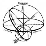 Point of the celestial sphere above the observer's head
 Common peacock (Indian)
 What is the name of the male and female