Homemade cnc machine drawing. How to make a homemade cnc router for metal
To make a three-dimensional drawing on wooden surface factory CNC milling machines for wood are used. It is difficult to make a similar mini-model with your own hands at home, but it is possible with a detailed study of the design. To do this, you need to understand the specifics, choose the right components and configure them.
The principle of operation of the milling machine
Modern woodworking equipment with a numerical block program control designed to form a complex pattern on wood. The design must contain a mechanical electronic part. In combination, they will automate the work process as much as possible.
To make a desktop on wood with your own hands, you should familiarize yourself with the main components. The cutting element is a cutter, which is installed in a spindle located on the motor shaft. This design is attached to the frame. It can move along two coordinate axes - x; y. To fix the workpiece, it is necessary to make a support table.
The electronic control unit is connected to the stepper motors. They provide displacement of the carriage relative to the part. Using this technology, you can make 3D drawings on a wooden surface.
The sequence of operation of mini-equipment with CNC, which you can make yourself.
- Writing a program according to which the sequence of movements of the cutting part will be performed. To do this, it is best to use special software systems designed for adaptation in home-made models.
- Setting the workpiece on the table.
- Program output to the CNC.
- Turning on equipment, monitoring the implementation of automatic actions.
To achieve maximum automation of work in 3D mode, you will need to correctly draw up a diagram and select the appropriate components. Experts recommend studying factory models before making a mini- milling machine with your own hands.
To create complex patterns and patterns on a wooden surface, you will need several types of cutters. Some of them you can do yourself, but for fine work, you should purchase factory ones.
Scheme of a homemade milling machine with numerical control

The most difficult stage is the choice of the optimal manufacturing scheme. It depends on the dimensions of the workpiece and the degree of its processing. For home use it is advisable to make a do-it-yourself desktop, which will have the optimal number of functions.

The best option is the manufacture of two carriages that will move along the x coordinate axes; y. It is best to use ground steel bars as a base. Carriages will be mounted on them. To create a transmission, stepper motors and screws with rolling bearings are needed.
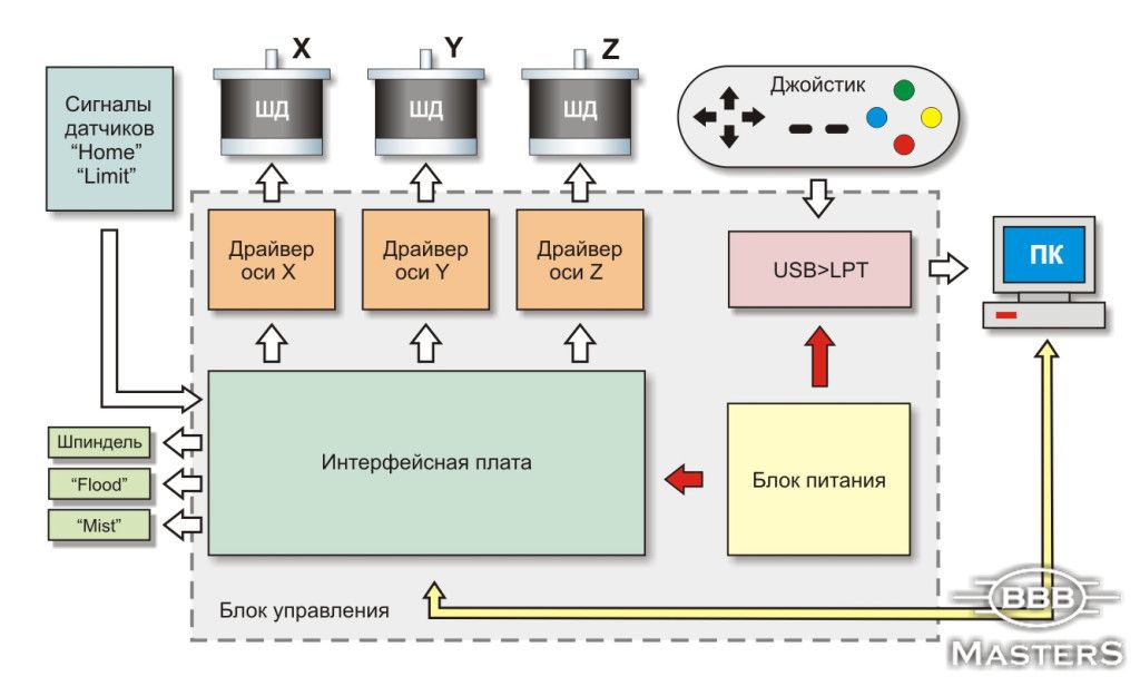
For maximum automation of the process in the design of a do-it-yourself mini CNC wood milling machine, it is necessary to think over the electronic part in detail. Conventionally, it consists of the following components:
- power unit. It is necessary to supply electricity to stepper motors and the controller chip. Often use the model 12v 3A;
- controller. It is designed to give commands to electric motors. For the operation of a do-it-yourself mini CNC milling machine, a simple circuit is enough to control the functioning of three motors;
- driver. It is also an element of regulation of the operation of the moving part of the structure.
The advantage of this complex is the ability to import executable files of the most common formats. Using a special application, you can create a three-dimensional drawing of the part for preliminary analysis. Stepper motors will run at a certain stroke rate. But for this you need to make technical specifications to the control program.
Choice of accessories for CNC milling machine

The next step is to select components for assembling homemade equipment. The best option is to use improvised means. As a basis for desktop models of a 3D machine, you can use wood, aluminum or plexiglass.
For correct operation of the entire complex, it is necessary to develop the design of calipers. During their movement, there should be no vibrations, this can lead to inaccurate milling. Therefore, before assembly, all components are checked for compatibility with each other.
- guides. Polished steel bars with a diameter of 12 mm are used. The length for the x-axis is 200mm, for the y-axis it is 90mm;
- caliper. Textolite is the best option. The usual size of the platform is 25*100*45 mm;
- stepper motors. Experts recommend using models from a 24v, 5A printer. Unlike disk drives, they have more power;
- cutter block. It can also be made from textolite. The configuration directly depends on the available tool.
The power supply is best assembled from the factory. At self-manufacturing errors are possible, which subsequently affect the operation of all equipment.
The procedure for manufacturing a CNC milling machine
After selecting all the components, you can make a desktop mini CNC wood router yourself with your own hands. All elements are preliminarily checked again, their dimensions and quality are checked.
To fix the elements of the equipment, it is necessary to use special fasteners. Their configuration and shape depend on the chosen scheme.
The procedure for assembling desktop mini CNC equipment for wood with a 3D processing function.
- Installation of caliper guides, their fixation on the side parts of the structure. These blocks are not installed on the base yet.
- Lapping of calipers. They must be moved along the guides until a smooth ride is obtained.
- Tightening the bolts to fix the calipers.
- Attaching components to the base of the equipment.
- Installation of lead screws together with couplings.
- Installation of drive motors. They are attached to the coupling screws.
The electronic part is located in a separate block. This helps to reduce the likelihood of malfunction during the operation of the router. Also important point is the choice of work surface for the installation of equipment. It must be level, since the level adjustment bolts are not provided in the design.
A condition for the performance of professional woodworking is the presence of a CNC milling machine. Commercially available roads and not everyone can afford it. Therefore, many make them with their own hands, saving money and enjoying the creative process.
There are two options for the manufacture of mini machines for milling wood:
- purchase of a set of parts and its manufacture (Modelist kits costing from 40 to 110 thousand rubles);
- make it with your own hands.
Consider the manufacture of mini CNC milling machines with your own hands.
Choice of design features
The list of actions in the development, manufacture of a mini device for wood milling is as follows:
- Initially, you need to decide what kind of work we are talking about. This will tell you what dimensions and thicknesses of parts can be processed on it.
- Make a layout and an estimated list of parts for a homemade desktop machine for DIY manufacturing.
- Choose software by bringing it in working condition so that it works according to the given program.
- Purchase the necessary components, parts, products.
- Having drawings, make the missing elements with your own hands, assemble and debug the finished product.
Design
A homemade machine consists of the following main parts:
- bed with a table placed on it;
- calipers with the ability to move the cutting cutter in three coordinates;
- spindle with cutter;
- guides for moving calipers and portal;
- a power supply unit that provides electricity to the motors, a controller or a switching board using microcircuits;
- drivers to stabilize the work;
- sawdust vacuum cleaner.
Guides are installed on the frame to move the portal along the Y axis. Guides are placed on the portal to move the caliper along the X axis. The spindle with the cutter is mounted on the caliper. It moves along its guides (Z-axis).
The controller and drivers provide automation of the CNC machine by transmitting commands to the electric motors. Using the Kcam software package allows you to use any controller and provides motor control in accordance with the part drawing entered into the program.
The design must be made rigid in order to withstand the working forces that arise during operation and not lead to vibrations. Vibrations will lead to a decrease in the quality of the resulting product, tool breakage. Therefore, the dimensions of the fasteners must ensure the solidity of the structure.
A homemade CNC milling machine is used to obtain a three-dimensional 3D image on wood detail. It is fixed on the table this device. It can also be used as an engraver. The design ensures the movement of the working body - the spindle with the cutter installed in accordance with the specified program of actions. The movement of the caliper along the X and Y axes occurs along polished guides using stepper motors.
Moving the spindle along the vertical Z axis allows you to change the depth of processing on the created drawing on the tree. To obtain a 3D relief drawing, you need to make drawings. It is advisable to use different kinds cutters that will allow you to get best options picture display.
Selection of components
For guides, steel rods D = 12 mm are used. For better movement of the carriages, they are ground. Their length depends on the size of the table. You can use hardened steel rods from a dot matrix printer.
Stepper motors can be used from there. Their parameters: 24 V, 5 A.
It is desirable to provide fixing of cutters with a collet.
It is better to use a factory-made power supply for a home-made mini milling machine, since performance depends on it.
The controller needs to use capacitors and resistors in SMD packages for surface mounting.
Assembly
To assemble a home-made machine for milling 3D wood parts with your own hands, you need to make drawings, prepare essential tool, accessories, make the missing parts. After that, you can start assembling.
The do-it-yourself assembly sequence of a mini CNC machine with 3D processing consists of:
- caliper guides are installed in the sidewalls together with the carriage (without screws).
- the carriages are moved along the guides until their motion becomes smooth. Thus, the holes in the caliper are lapped.
- tightening bolts on calipers.
- fixing assembly units on the machine and installing screws.
- installation of stepper motors and their connection with screws using couplings.
- the controller is allocated in a separate block to reduce the influence of operating mechanisms on it.
A homemade CNC machine after assembly must be tested! Testing 3D processing is carried out by using sparing modes to identify all problems and fix them.
Operation in automatic mode is provided by software. Advanced computer users can use power supplies and drivers for controllers, stepper motors. The power supply converts the incoming AC (220 V, 50 Hz) into D.C. needed to power the controller and stepper motors. For them, machine control from a personal computer passes through the LPT port. Working programs are Turbo CNC and VRI-CNC. CorelDRAW and ArtCAM graphic editor programs are used to prepare the drawings necessary for implementation in a tree.
Results
Homemade mini CNC milling machine for 3D parts is easy to operate, ensures accuracy and quality of processing. If you need to do more complex work, you need to use stepper motors of greater power (for example: 57BYGH-401A). In this case, to move the calipers, you need to use toothed belts to rotate the screws, and not a clutch.
The installation of the power supply (S-250-24), switching board, drivers can be done in the old case from the computer, modifying it. It can be equipped with a red "stop" button for emergency shutdown of equipment.
If you find an error, please highlight a piece of text and click Ctrl+Enter.
A set with which you can assemble your CNC milling machine.
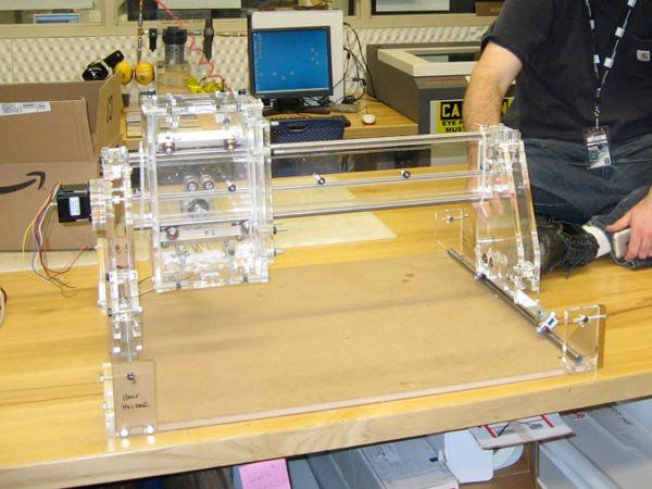
Ready-made machine tools are sold in China, a review of one of them has already been published on Muska. We will assemble the machine ourselves. Welcome…
UPD: file links
I will still give a link to a review of the finished machine from AndyBig. I will not repeat myself, I will not quote his text, we will write everything from scratch. The title only lists a set with engines and a driver, there will be more parts, I'll try to give links to everything.
And this ... I apologize in advance to the readers, I did not specifically take photos in the process, because. at that moment I was not going to do a review, but I will raise a maximum of photos of the process and try to give detailed description all nodes.
The purpose of the review is not so much to brag as to show the opportunity to make an assistant for yourself. I hope this review will give someone an idea, and it is possible not only to repeat, but also to make it even better. Go…
How the idea was born:
It so happened that I have been associated with drawings for a long time. Those. my professional activity closely associated with them. But it's one thing when you make a drawing, and then completely different people bring the design object to life, and it's quite another when you bring the design object to life yourself. And if with building things I seem to be doing okay, then with modeling and other applied arts, not really.
So for a long time there was a dream from an image drawn in AutoCAD, to make a whack - and it is in kind in front of you, you can use it. This idea slipped from time to time, but could not take shape in anything concrete, until ...
Until I saw REP-RAP three or four years ago. Well, the 3D printer was a very interesting thing, and the idea to assemble myself took a long time to take shape, I collected information about different models about the pros and cons different options. At one point, by clicking on one of the links, I got to a forum where people were sitting and discussing not 3D printers, but CNC milling machines. And from here, perhaps, the hobby begins its journey.
Instead of theory
In a nutshell about CNC milling machines (I write in my own words intentionally, without copying articles, textbooks and manuals).
A milling machine works exactly the opposite of a 3D printer. In the printer, step by step, layer by layer, the model is built up by fusing polymers, in a milling machine, with the help of a cutter, “everything superfluous” is removed from the workpiece and the required model is obtained.
To operate such a machine, you need the necessary minimum.
1. Base (body) with linear guides and transmission mechanism (can be screw or belt)
2. Spindle (I see someone smiled, but that's what it's called) - the actual engine with a collet into which a working tool is installed - a milling cutter.
3. Stepper motors - motors that allow controlled angular movements.
4. Controller - a control board that transmits voltage to the motors in accordance with the signals received from the control program.
5. Computer with installed control program.
6. Basic drawing skills, patience, desire and good mood.))
The points:
1. Base.
by configuration:
I will divide into 2 types, there are more exotic options, but the main 2:
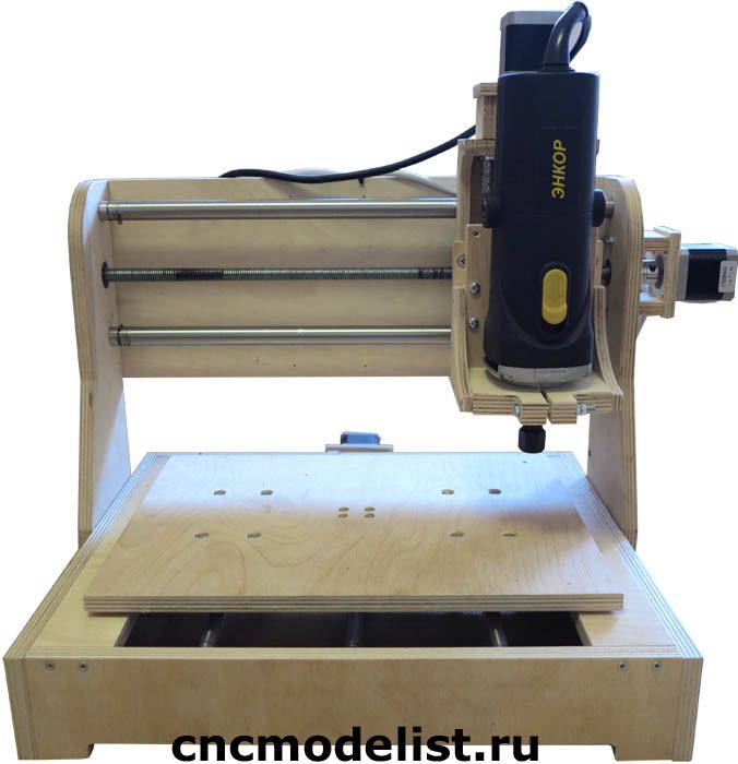
With movable portal:
Actually, the design I have chosen, it has a base on which guides are fixed along the X axis. A portal moves along the X-axis guides, on which the Y-axis guides are located, and the Z-axis node moving along it.
With static portal
This design represents itself as a body, it is also a portal on which the Y-axis guides are located, and the Z-axis node moving along it, and the X-axis is already moving relative to the portal.
By material:
body can be made from different materials, the most common:
- duralumin - has a good ratio of mass, rigidity, but the price (just for a hobby homemade product) is still depressing, although if there are views on the machine for making serious money, then there are no options.
- plywood - good rigidity with sufficient thickness, low weight, the ability to process with anything :), and the price itself, a sheet of plywood 17 is now quite inexpensive.
- steel - often used on machines with a large processing area. Such a machine, of course, must be static (not mobile) and heavy.
- MFD, plexiglass and monolithic polycarbonate, even chipboard - also saw such options.
As you can see, the design of the machine itself is very similar to both a 3D printer and laser engravers.
I deliberately do not write about the designs of 4, 5 and 6-axis milling machines, because. on the agenda is a homemade hobby machine.
2. Spindle.
Actually, spindles come with air and water cooling.
Air-cooled are cheaper in the end, because. for them it is not necessary to block an additional water circuit, they work a little louder than water ones. Cooling is provided by a back side an impeller, which at high speeds creates a tangible air flow that cools the engine housing. The more powerful the engine, the more serious the cooling and the greater the air flow, which may well inflate in all directions
dust (shavings, sawdust) of the workpiece.
Water cooled. Such a spindle works almost silently, but in the end, anyway, the difference between them in the process of work cannot be heard, since the sound of the material being processed by the cutter will block it. There is no draft from the impeller, in this case, of course, but there is an additional hydraulic circuit. In such a circuit, there must be pipelines, a pump for pumping liquid, as well as a place for cooling (radiator with airflow). Usually not water is poured into this circuit, but either TOSOL or Ethylene glycol.
There are also spindles of various capacities, and if low-power ones can be connected directly to the control board, then motors with a power of 1 kW or more must be connected through the control unit, but this is not about us.))
Yes, often in home-made machines they install direct grinders, or milling cutters with a removable base. Such a decision can be justified, especially when performing work of a short duration.
In my case, a 300W air-cooled spindle was chosen.
3. Stepper motors.
The most widely used motors are 3 sizes
NEMA17, NEMA23, NEMA 32
they differ in size, power and working moment
NEMA17 are usually used in 3D printers, they are too small for a milling machine, because. you have to carry a heavy portal, to which a lateral load is additionally applied during processing.
NEMA32 for such a craft is unnecessary, besides, you would have to take another control board.
my choice fell on NEMA23 with a maximum power for this board - 3A.
Also, people use steppers from printers, but since. I didn’t have them either and still had to buy, I chose everything in the kit.
4. Controller
A control board that receives signals from the computer and transmits voltage to stepper motors that move the axes of the machine.
5. Computer
You need a separate computer (possibly very old) and there are, perhaps, two reasons for this:
1. It is unlikely that you will decide to place a milling machine next to the place where you are used to reading the Internet, playing toys, doing bookkeeping, etc. Simply because the milling machine is loud and dusty. Usually the machine is either in the workshop or in the garage (better heated). My machine is in the garage, it is mostly idle in winter, because. no heating.
2. For economic reasons, computers are usually used that are no longer relevant for home life - heavily used :)
Requirements for the car by and large about nothing:
- from Pentium 4
- the presence of a discrete video card
- RAM from 512MB
- the presence of an LPT connector (I won’t say anything about USB, I haven’t studied the news yet because of the driver that works on LPT)
such a computer is either taken from the pantry, or, as in my case, is bought for next to nothing.
Due to the low power of the machine, we try not to install additional software, i. axle only and control program.
Next are two options:
- install windows XP (it's a weak computer, remember right?) and the MATCH3 control program (there are others, but this is the most popular)
- we put niks and Linux CNC (they say that everything is also very good, but I didn’t master niks)
I will add, perhaps, in order not to offend overly wealthy people, that it is quite possible to put not a fourth stump, but some kind of ai7 - please, if you like it and can afford it.
6. Basic drawing skills, patience, desire and good mood.
Here in a nutshell.
To operate the machine, you need a control program (essentially a text file containing the coordinates of movements, movement speed and acceleration), which in turn is prepared in a CAM application - usually ArtCam, in this application the model itself is prepared, its dimensions are set, and a cutting tool is selected.
I usually take a slightly longer route, make a drawing, and then AutoCad, saving it *.dxf, upload it to ArtCam and prepare the UE there.
Well, let's start the process of creating your own.
Before designing a machine, we take several points as starting points:
- Axle shafts will be made of construction studs with M10 thread. Of course, there are undoubtedly more technological options: a shaft with a trapezoidal thread, a ball screw (ball screw), but you need to understand that the price of the issue leaves much to be desired, and for a hobby machine, the price is generally space. However, over time, I'm going to upgrade and replace the hairpin with a trapezoid.
- The material of the machine body is 16mm plywood. Why plywood? Available, cheap, cheerful. There are actually many options, someone makes from duralumin, someone from plexiglass. I prefer plywood.
Making a 3D model: 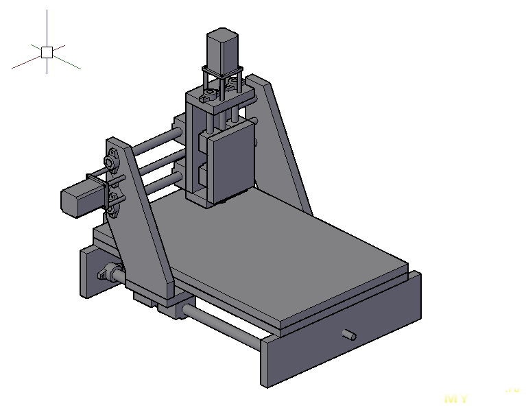
Reamer: 
Then I did this, there was no picture left, but I think it will be clear. I printed out a scan on transparent sheets, cut them out and pasted them onto a sheet of plywood.
Sawed pieces and drilled holes. Of the tools - a jigsaw and a screwdriver.
There is one more little trick that will make life easier in the future: before drilling holes, squeeze all paired parts with a clamp and drill through, so you get holes that are equally located on each part. Even if a slight deviation occurs during drilling, the internal parts of the connected parts will match, and the hole can be reamed a little.
In parallel, we make a specification and start ordering everything.
what happened to me:
1. The set specified in this review includes: stepper motor control board (driver), NEMA23 stepper motors - 3 pcs., 12V power supply, LPT cord and cooler.
2. Spindle (this is the simplest, but nevertheless does its job), fasteners and a 12V power supply.
3. Used computer Pentium 4, most importantly, the motherboard has LPT and a discrete video card + CRT monitor. I took it to Avito for 1000 rubles.
4. Steel shaft: Ф20mm - L=500mm - 2pcs, Ф16mm - L=500mm - 2pcs, Ф12mm - L=300mm - 2pcs.
I took it here, at that time in St. Petersburg it turned out to be more expensive to take. Came within 2 weeks.
5. Linear bearings: f20 - 4 pcs., f16 - 4 pcs., f12 - 4 pcs.
20
16
12
6. Fastenings for shafts: f20 - 4 pcs., f16 - 4 pcs., f12 - 2 pcs.
20
16
12
7. Caprolon nuts with M10 thread - 3 pcs.
I took along with the shafts on duxe.ru
8. Rotation bearings, closed - 6 pcs.
In the same place, but the Chinese also have a lot of them
9. PVA wire 4x2.5
it's offline
10. Cogs, dowels, nuts, clamps - a bunch.
This is also offline, in hardware.
11. A set of cutters was also bought
So, we order, wait, cut and collect. 

Initially, the driver and power supply for it were installed in the case with the computer together. ![]()
Later it was decided to place the driver in a separate case, it just appeared. 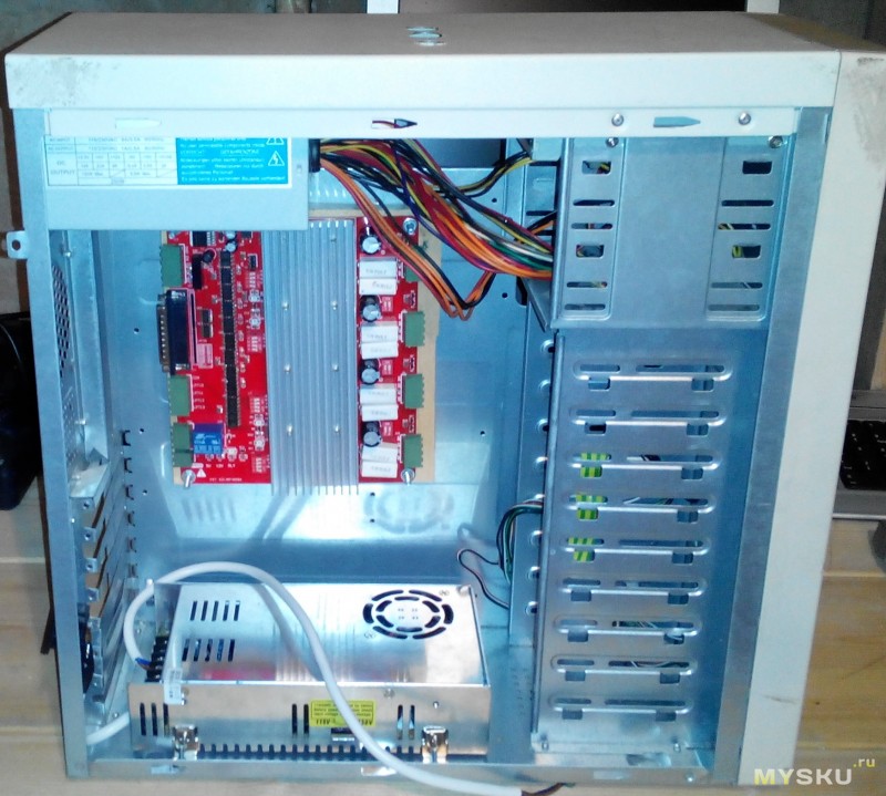
Well, the old monitor somehow changed to a more modern one. 
As I said at the beginning, I never thought that I would write a review, so I am attaching photos of the nodes, and I will try to explain the assembly process.
First, we assemble three axles without screws in order to align the shafts as accurately as possible.
We take the front and rear walls of the housing, fasten the flanges for the shafts. We string 2 linear bearings on the X axis and insert them into the flanges. 
We fasten the bottom of the portal to the linear bearings, we try to roll the base of the portal back and forth. We are convinced of the curvature of our hands, we disassemble everything and drill holes a little.
Thus, we get some freedom of movement of the shafts. Now we bait the flanges, insert the shafts into them and move the base of the portal back and forth to achieve a smooth glide. We tighten the flanges.
At this stage, it is necessary to check the horizontalness of the shafts, as well as their alignment along the Z axis (in short, so that the distance from the assembly table to the shafts is the same) so as not to fill up the future work plane later.
We figured out the X axis.
We fasten the portal racks to the base, for this I used furniture barrels. 
Fasten the flanges for the Y axis to the uprights, this time from the outside: 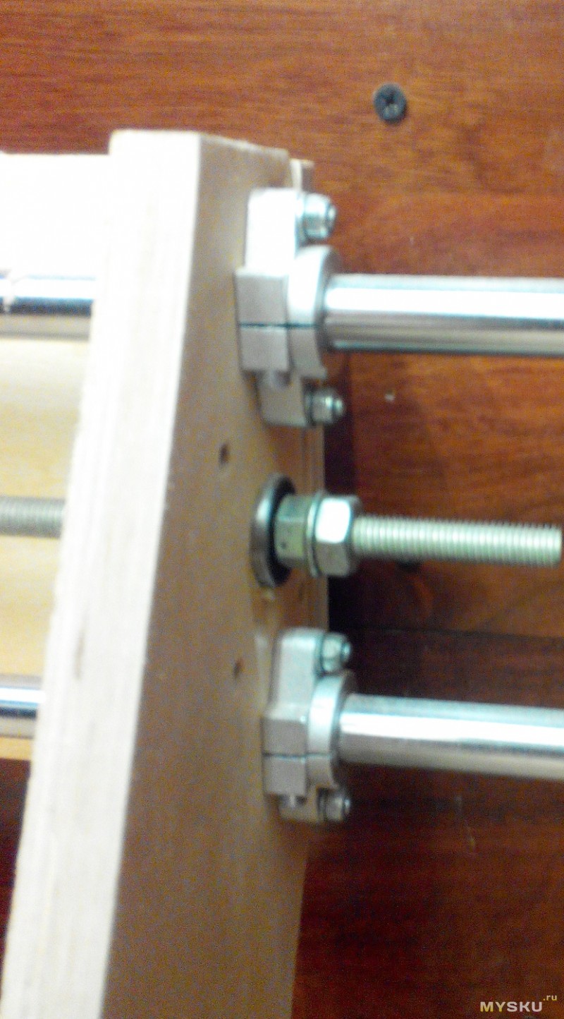
We insert shafts with linear bearings.
We fix the back wall of the Z axis.
We repeat the process of adjusting the parallelism of the shafts and fix the flanges.
We repeat the same process with the Z axis.
We get a rather funny design that can be moved with one hand along three coordinates.
An important point: all axes should move easily, i.e. slightly tilting the structure, the portal itself should move freely, without any squeaks and resistance.
Next, attach the lead screws.
We cut off the M10 construction stud of the required length, screw the caprolon nut approximately in the middle, and 2 M10 nuts on each side. It is convenient for this, after tightening the nuts a little, clamp the stud into the screwdriver and, holding the nuts, tighten.
We insert the bearings into the sockets and push the studs into them from the inside. After that, we fix the studs to the bearing with nuts on each side and counter with the second so that they do not come loose.
We fasten the caprolon nut to the base of the axle.
We clamp the end of the stud into the screwdriver and try to move the axis from start to finish and return.
Here we have a couple more joys waiting for us:
1. The distance from the axis of the nut to the base in the center (and most likely at the time of assembly the base will be in the middle) may not coincide with the distance in extreme positions, because shafts under the weight of the structure can bend. I had to put cardboard along the X axis.
2. Shaft travel can be very tight. If you have eliminated all distortions, then tension can play a role, here it is necessary to catch the moment of tension of fixing with nuts to the installed bearing.
Having dealt with the problems and having received free rotation from start to finish, we proceed to install the remaining screws.
We attach stepper motors to the screws:
In general, when using special screws, whether it be a trapezoid or a ball screw, the ends are processed on them and then the connection to the engine is very conveniently made with a special coupling. 
But we have a construction stud and had to think about how to fix it. At that moment, I came across a cut gas pipe, and applied it. It directly “winds” onto the hairpin on the engine, enters the grinding, tightened it with clamps - it holds very well. ![]()
To fix the engines, I took an aluminum tube and cut it. Adjusted with washers.
To connect the engines, I took the following connectors: 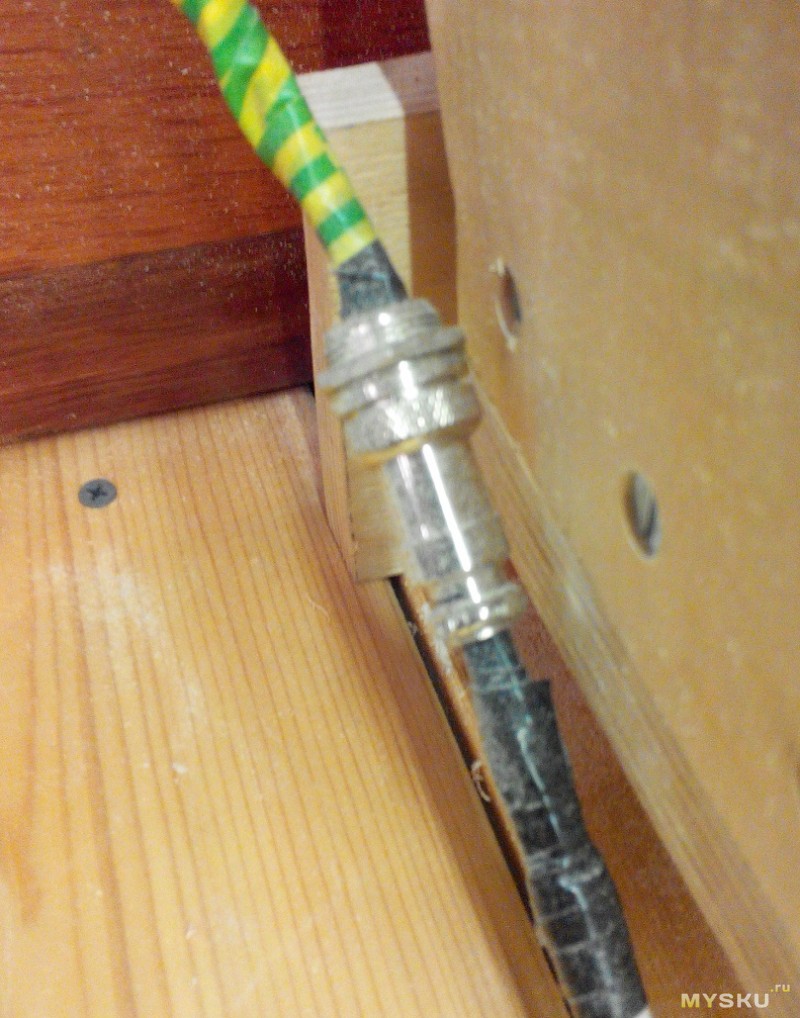

Sorry, I don’t remember what they are called, I hope someone in the comments will tell you.
GX16-4 connector (thanks Jager). I asked a colleague to buy in an electronics store, he just lives nearby, but it turned out to be very inconvenient for me to get there. I am very pleased with them: they hold them securely, they are designed for a higher current, you can always disconnect them.
We put the working field, it is also a sacrificial table.
We connect all the motors to the control board from the review, connect it to a 12V PSU, connect to the computer with an LPT cable.
Install MACH3 on PC, make settings and try!
About the setting separately, perhaps, I will not write. It could go on for a couple more pages.
I have a whole joy, the video of the first launch of the machine has been preserved:
Yes, when this video was moving along the X axis, there was a terrible bounce, unfortunately I don’t remember exactly, but in the end I found either the washer dangling, or something else, in general, it was solved without problems.
Next, you need to put the spindle, while ensuring its perpendicularity (simultaneously in X and Y) to the working plane. The essence of the procedure is this, we attach a pencil to the spindle with electrical tape, thus indenting from the axis is obtained. With a smooth lowering of the pencil, he begins to draw a circle on the board. If the spindle is littered, then it turns out not a circle, but an arc. Accordingly, it is necessary to achieve alignment by drawing a circle. A photo from the process has been preserved, the pencil is out of focus, and the angle is not the same, but I think the essence is clear: 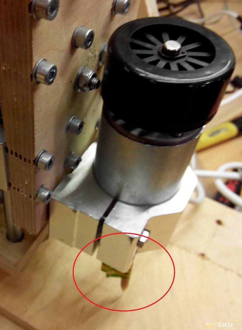
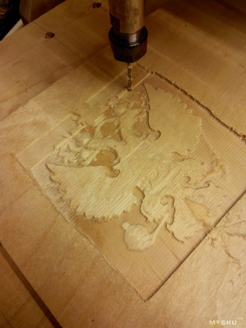
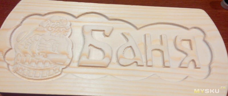
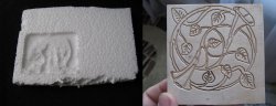
We find a finished model (in my case, the coat of arms of the Russian Federation), prepare the UE, feed it to MACH and go!
Machine operation:
photo in progress:
Well, of course we go through the initiation))
The situation is both funny and generally understandable. We dream of building a machine and immediately sawing something super cool, but in the end we understand that this time will just take a lot of time.
In a nutshell:
With 2D processing (simply sawing out), a contour is set, which is cut out in several passes.
With 3D processing (here you can immerse yourself in a holivar, some argue that this is not 3D but 2.5D, since the workpiece is processed only from above), a complex surface is set. And the higher the accuracy of the desired result, the thinner the cutter is used, the more passes of this cutter are needed.
To speed up the process, roughing is used. Those. first, the main volume is sampled with a large cutter, then finishing with a thin cutter is started.
Next, we try, set up, experiment, etc. The 10000 hour rule works here too ;)
Perhaps I will no longer bore you with a story about the construction, tuning, etc. It's time to show the results of using the machine - the product. 
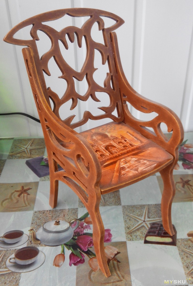

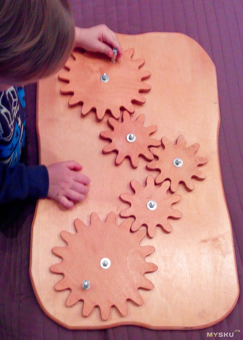
As you can see, these are mostly sawn contours or 2D processing. It takes a lot of time to process three-dimensional figures, the machine is in the garage, and I stop by there for a short time.
Here they will rightly notice me - but on ... to build such a bandura, if you can cut a figure with a U-shaped jigsaw or an electric jigsaw?
It is possible, but this is not our method. As you remember, at the beginning of the text, I wrote that it was the idea to make a drawing on a computer and turn this drawing into a product that served as the impetus for the creation of this beast.
Writing a review finally pushed me to upgrade the machine. Those. the upgrade was planned earlier, but "hands did not reach." Last change before that there was an organization of a house for the machine: 
Thus, in the garage, when the machine is running, it has become much quieter and much less dust flies.
The last upgrade was the installation of a new spindle, more precisely, now I have two interchangeable bases:
1. With Chinese 300W spindle for fine work: 
2. With a domestic, but no less Chinese milling cutter "Enkor" ... 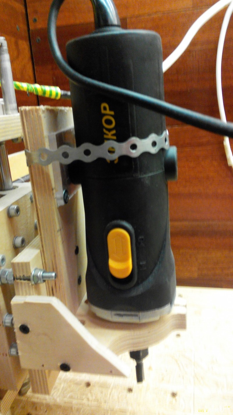
With the new router came new possibilities.
Faster processing, more dust.
Here is the result of using a semi-circular groove cutter: 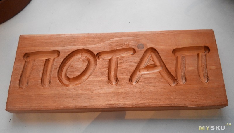
Well, especially for MYSKU
Simple straight groove cutter: ![]()
Process video:
On this I will curtail, but according to the rules it would be necessary to take stock.
Minuses:
- Expensive.
- For a long time.
- From time to time you have to solve new problems (they turned off the light, pickups, something unraveled, etc.)
Pros:
- The process of creation. Only this already justifies the creation of the machine. The search for solutions to emerging problems and implementation is what, instead of sitting on your butt, you get up and go to do something.
- Joy at the moment of giving gifts made with your own hands. Here it must be added that the machine does not do all the work itself :) in addition to milling, it is still necessary to process it, sand it, paint it, etc.
Thank you very much if you are still reading. I hope that my post, even if it does not incite you to create such (or another) machine, will broaden your horizons and give food for thought. I also want to say thank you to those who persuaded me to write this opus, without it I didn’t have an upgrade, apparently, so everything is in the black.
I apologize for the inaccuracies in the wording and any lyrical digressions. Much had to be cut, otherwise the text would have turned out to be simply immense. Clarifications and additions are naturally possible, write in the comments - I will try to answer everyone.
Good luck in your endeavors!
Promised file links:
- machine drawing,
- sweep,
format is dxf. This means that you can open the file with any vector editor.
The 3D model is detailed by 85-90 percent, I did many things, either at the time of preparing the scan, or in place. Please understand and forgive.)
A CNC router can be a great helper in small-scale production or home repair. The cost of factory CNC milling machines (cnc) is quite high, so some craftsmen successfully create them with their own hands according to unique drawings.
Making a homemade cnc machine with your own hands is not easy, sometimes it takes several months.
Machine design
The easiest way to make a frame for a homemade milling machine for metal is from a pipe square section 80 x 80 mm, fairly low. The low height makes the device quite stable and prevents vibration. The stand for fixing the rails is also made of rectangular metal pipe 60 x 20 mm. The bed is bolted, as welded joints deform the structure. Bolted fasteners allow you to set the device exactly on the level, the contact area is large, the fastening is reliable and fairly rigid, without backlash.
Working area size homemade machine must be made from 32 x 35 cm. The length of the guide shafts along Y and X is 1.6 cm, along Z - 1 cm.
Guides are best made profile, otherwise they will sag along the X axis.
Plain bearings are better to choose industrial, albeit the most inexpensive. Their use will reduce the likelihood of backlash.
The Z axis is mounted on a screw gear, as it is quite heavy. To transmit torsion to the lead screw from the Z-axis, a toothed belt with a width of 10 mm is used. Such a scheme allows you to reduce the beating and facilitate the placement of the stepper motor relative to the travel screw. Reduces machine weight and saves vertical space.
The axle itself is made from an aluminum plate, and two stepper motors are installed behind it. Their purpose is to transfer torsion to the Z-axis screw by means of a toothed belt, another motor transmits movement along the X-axis with a belt. The Z-axis lead screw can be made from a construction stud.
If instead of a belt a screw gear is made in the drawing, the speed will increase to 850 rpm and the accuracy of a home-made cnc machine. But this design is much more expensive.
If you plan to water-cool the spindle, you should also provide a water pump, as well as a set of rubber tubes.
Engine and software
For a homemade CNC milling machine (they are also called cnc), a stepper motor with a torque of 18 kg / cm is suitable. Such a motor is sufficient for a spindle with a power of 1.5 kilowatts. It will turn out to process parts made of soft metals and simple jobs on carbon steel.
The controller, frequency convector and motherboard can be installed in a single protective box. Although many are afraid of interference, they are quite rare. Such a control center is prone to overheating in hot weather!
CNC milling machines, assembled by hand according to drawings, work under the guidance of Linux. Some drivers will have to be written by hand, for example, for a stepper motor with microstepping. Controllers with USB output do not work under Linux, this should be taken into account when choosing them. You need to buy a four-axis controller and make the appropriate settings.
Ready set for machine assembly
Most craftsmen who assemble the machine with their own hands are faced with the need to purchase many finished parts. As a result, the price homemade device may be higher than factory. Process self assembly very long, and the result is often disappointing. Often, craftsmen remake several times machines assembled without drawings and calculations, bringing their work to the desired standard.
It is possible to make a CNC router with your own hands using a wrench and a screwdriver in one working day, using a ready-made kit - a kind of simple constructor for adults, containing absolutely all the details and drawings. The set is a guarantee High Quality future machine.
The device and testing of a homemade milling cutter:
17
A guide to creating a CNC milling CNC machine. Chapter 1 Machine Electronics
Good day! And here I am with a new part of my story about CNC - machine tool. When I started writing the article, I did not even think that it would turn out to be so voluminous. When I wrote about the electronics of the machine, I looked and got scared - the A4 sheet was written on both sides, and there was still a lot to tell.
In the end it turned out like this manual for creating a CNC machine, working machine, from scratch. There will be three parts of the article about one machine: 1-electronic stuffing, 2-mechanics of the machine, 3-all the details of setting up the electronics, the machine itself, and the machine control program.
In general, I will try to combine in one material everything useful and necessary for every beginner in this interesting business, what I myself read on various Internet resources and passed through myself. By the way, in that article I forgot to show photos of crafts made. I'm fixing this. Styrofoam bear and plywood plant.
Foreword
After I assembled my little machine without significant expenditure of effort, time and money, I was seriously interested in this topic. I looked on YouTube, if not all, then almost all the videos related to amateur machines. Particularly impressive were the photographs of products that people make on their “ Home CNC". I looked and decided - I will assemble my big machine! So, on a wave of emotions, I didn’t think it over well, I plunged into a new and unknown world for myself CNC.Didn't know where to start. First of all, I ordered a normal stepper motor Vexta 12 kg/cm, among other things with the proud inscription "made in Japan".

While he was driving through all of Russia, he sat in the evenings at various CNC forums and tried to make a choice STEP/DIR controller and stepper motor drivers. I considered three options: on a microcircuit L298, on field workers, or buy ready-made Chinese TB6560 about which there were very conflicting reviews.
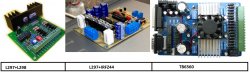
For some, it worked without problems for a long time, for others it burned out at the slightest user error. Someone even wrote that he burned out when he slightly turned the shaft of the motor connected at that time to the controller. Probably the fact of the unreliability of the Chinese and played in favor of choosing a scheme L297+ actively discussed on the forum. The scheme is probably really unkillable. the field drivers of the driver by amperes are several times higher than what needs to be fed to the motors. Even if you need to solder yourself (this is only a plus), and the cost of the parts came out a little more than the Chinese controller, but it is reliable, which is more important.
I'll digress a little from the topic. When all this was done, I didn’t even have the thought that someday I would write about it. Therefore, there are no photos of the assembly process of mechanics and electronics, only a few photos taken on a mobile phone camera. Everything else I clicked specifically for the article, already assembled.
The case of the soldering iron is afraid
I'll start with the power supply. I planned to make an impulse, I fiddled with it for probably a week, but I could not defeat the excitement, which came from nowhere. I wind the trance at 12v - everything is OK, I wind it at 30 - a complete mess. I came to the conclusion that some kind of bullshit climbs on feedback from 30v to TL494 and tear down her tower. So I abandoned this impulse, since there were several TS-180s, one of which went to serve the motherland as a power trance. And whatever you say, a piece of iron and copper will be more reliable than a bunch of crumbling. The transformer rewound to the required voltages, but it was necessary + 30V to power the motors, + 15V to power IR2104, +5v on L297, and a fan. You can apply 10 or 70 to the motors, the main thing is not to exceed the current, but if you do less, the maximum speed and power decrease, but the transformer no longer allowed it. I needed 6-7A. Stabilized voltages 5 and 15v, left 30 “floating” at the discretion of our power grid.
All this time, every night I sat at the computer and read, read, read. Setting up the controller, choosing programs: which one to draw, which one to operate the machine, how to make mechanics, etc. etc. In general, the more I read, the more terrible it became, and more and more often the question arose “what for do I need this ?!”. But it was too late to retreat, the engine was on the table, the details were somewhere along the way - we must continue.
It's time to solder the board. Available on the Internet did not suit me for three reasons:
1 - The store that ordered the parts was not there IR2104 in DIP packages, and they sent me 8-SOICN. They are soldered to the board on the other side, upside down, and accordingly it was necessary to mirror the tracks, and them ( IR2104) 12 pieces.
2 - Resistors and capacitors are also taken in SMD packages to reduce the number of holes that had to be drilled.
3 - The radiator I had was smaller and the extreme transistors were out of its area. It was necessary to shift the field workers on one board to the right, and on the other to the left, so I made two types of board.
Machine controller diagram
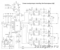
For the safety of the LPT port, the controller and the computer are connected via an optocoupler board. I took the scheme and the signet from one well-known site, but again I had to redo it a bit for myself and remove unnecessary details.
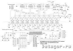
One side of the board is powered via the USB port, the other, connected to the controller, is powered by a + 5V source. Signals are transmitted via optocouplers. I will write all the details about setting up the controller and decoupling in the third chapter, but here I will only mention the main points. This decoupling board is designed for safe connection of the stepper motor controller to the LPT port of the computer. Completely electrically isolates the computer port from the machine electronics, and allows you to control a 4-axis CNC machine. If the machine has only three axes, as in our case, unnecessary parts can be left hanging in the air, or not soldered at all. It is possible to connect end sensors, a forced stop button, a spindle enable relay and another device, such as a vacuum cleaner.

It was a photo of the optocoupler board taken from the Internet, and this is what my garden looks like after installation in the case. Two boards and a bunch of wires. But there seems to be no interference, and everything works without errors.

The first controller board is ready, I checked everything and tested it step by step, as in the instructions. I set a small current as a trimmer (this is possible due to the presence of PWM), and connected the power (motors) through a chain of 12 + 24v light bulbs so that it was “nothing if nothing”. I have field workers without a radiator.
The engine hissed. Good news, so PWM works as it should. I press a key and it spins! I forgot to mention that this controller is designed to control a bipolar stepper motor i.e. one with 4 wires. Played with step / half step modes, current. In half-step mode, the engine behaves more stable and develops high speeds + accuracy increases. So I left the jumper in the "half step". With the maximum safe current for the engine at a voltage of about 30V, it turned out to spin the engine up to 2500 rpm! My first machine without PWM never dreamed of such a thing.))
The next two motors ordered more powerful, Nema at 18kg/s, but already “made in China”.
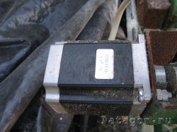
They are inferior in quality Vexta After all, China and Japan are two different things. When you rotate the shaft with your hand, the Japanese do it somehow softly, but the Chinese have a different feeling, but so far this has not affected work. There are no comments for them.
I soldered the remaining two boards, checked through the "LED stepper motor simulator", everything seems to be fine. I connect one motor - it works fine, but not 2500 rpm, but about 3000! According to the already worked out scheme, I connect the third motor to the third board, spins for a couple of seconds and gets up ... I look at the oscilloscope - there are no pulses on one output. I call the fee - one of IR2104 pierced.
Well, maybe I got a defective one, I read that this often happens with this mikruha. I solder a new one (I took 2 pieces with a margin), the same nonsense - it turns STOP for a couple of seconds! Here I strained myself, and let's check the field workers. By the way, my board has IRF530(100V / 17A) vs. (50V / 49A), as in the original. A maximum of 3A will go to the motor, so a reserve of 14A will be more than enough, but the difference in price is almost 2 times in favor of the 530s.
So, I check the field workers and what I see ... I didn’t solder one leg! And all 30V from the field worker flew to the output of this "irka". I soldered the leg, carefully examined everything again, put another one IR2104, I'm worried myself - this is the last one. I turned it on and was very happy when the engine did not stop after two seconds of operation. Modes left as follows: engine Vexta- 1.5A, engine NEMA 2.5A. At this current, revolutions of about 2000 are achieved, but it is better to limit them programmatically in order to avoid skipping steps, and the temperature of the engines at long work does not exceed the safe for motors. The power transformer copes without problems, because usually only 2 motors are spinning at the same time, but additional air cooling is desirable for the radiator.
Now about the installation of field workers on the radiator, and there are 24 of them, if anyone has not noticed. In this version of the board, they are located lying down, i.e. the radiator just lays down on them and is attracted by something.
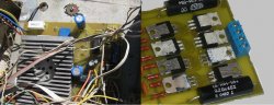
Of course, it is desirable to put a solid piece of mica to isolate the heatsink from the transistors, but I did not have one. Found a way out. Because in half of the transistors, the case goes to plus power; they can be mounted without insulation, just on thermal paste. And under the rest, I put pieces of mica left over from Soviet transistors. I drilled the radiator and the board in three places through and through and tightened it with bolts. I got one large board by soldering three separate boards around the edges, while soldering a 1mm copper wire around the perimeter for strength. I placed all the electronic stuffing and the power supply on some kind of iron chassis, I don’t even know why.
I cut out the side and top cover from plywood, and put a fan on top.

I drilled holes in the front panel for numerous LEDs for indicating operating modes.
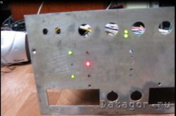
For quickly connecting / disconnecting engines and the control unit, I used connectors from the last millennium. And good contact desired current keep without any consequences for themselves.


