What is electrical resistance definition. What is electrical resistance
- an electrical quantity that characterizes the property of a material to prevent the flow of electric current. Depending on the type of material, resistance can tend to zero - be minimal (mi/micro ohms - conductors, metals), or be very large (giga ohms - insulation, dielectrics). The reciprocal of electrical resistance is .
unit of measurement electrical resistance - Ohm. It is denoted by the letter R. The dependence of resistance on current and in a closed circuit is determined.
Ohmmeter- a device for direct measurement of circuit resistance. Depending on the range of the measured value, they are divided into gigaohmmeters (for large resistances - when measuring insulation), and into micro / milliohmmeters (for small resistances - when measuring transitional resistances contacts, motor windings, etc.).
Exist big variety ohmmeters by design different manufacturers, from electromechanical to microelectronic. It is worth noting that a classic ohmmeter measures the active part of the resistance (the so-called ohms).
Any resistance (metal or semiconductor) in the circuit alternating current has an active and a reactive component. The sum of active and reactance is AC circuit impedance and is calculated by the formula:
where, Z is the total resistance of the AC circuit;
R is the active resistance of the AC circuit;
Xc is the capacitive reactance of the AC circuit; 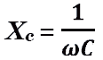
(C is the capacitance, w is the angular velocity of the alternating current)
Xl is the inductive reactance of the AC circuit; ![]()
(L is the inductance, w is the angular velocity of the alternating current).
Active resistance- this is part of the impedance of the electrical circuit, the energy of which is completely converted into other types of energy (mechanical, chemical, thermal). Distinctive property the active component is the total consumption of all electricity (energy is not returned to the network back to the network), and the reactance returns part of the energy back to the network (a negative property of the reactive component).
The physical meaning of active resistance
Every environment where electric charges, creates obstacles on their way (it is believed that these are the nodes of the crystal lattice), into which they seem to hit and lose their energy, which is released in the form of heat.
Thus, there is a drop (loss of electrical energy), part of which is lost due to the internal resistance of the conductive medium.
The numerical value characterizing the ability of a material to prevent the passage of charges is called resistance. It is measured in Ohms (Ohm) and is inversely proportional to the electrical conductivity.
Miscellaneous elements periodic system Mendeleev have different electrical resistivity (p), for example, the smallest sp. silver (0.016 Ohm * mm2 / m), copper (0.0175 Ohm * mm2 / m), gold (0.023) and aluminum (0.029) have resistance. They are used in industry as the main materials on which all electrical engineering and energy are built. Dielectrics, on the other hand, have a high sp. resistance and used for insulation.
The resistance of a conducting medium can vary significantly depending on the cross section, temperature, magnitude and frequency of the current. In addition, different media have different charge carriers (free electrons in metals, ions in electrolytes, "holes" in semiconductors), which are the determining factors of resistance.
The physical meaning of reactance
In coils and capacitors, when applied, energy is accumulated in the form of magnetic and electric fields, which requires some time.
Magnetic fields in alternating current networks change following the changing direction of movement of charges, while providing additional resistance.
In addition, there is a stable phase shift and current strength, and this leads to additional losses of electricity.
Resistivity
How to find out the resistance of a material if it does not flow through it and we do not have an ohmmeter? There is a special value for this - electrical resistivity of the material in
(these are tabular values that are determined empirically for most metals). With this value and the physical quantities of the material, we can calculate the resistance using the formula:
where, p- resistivity (units of measurement ohm * m / mm 2);
l is the length of the conductor (m);
S - cross section (mm 2).
§ fifteen. Electrical resistance
The directed movement of electric charges in any conductor is hindered by the molecules and atoms of this conductor. Therefore, both the external section of the circuit and the internal one (inside the energy source itself) interfere with the passage of current. The value characterizing the resistance of an electric circuit to the passage of electric current is called electrical resistance.
The source of electrical energy, included in a closed electrical circuit, consumes energy to overcome the resistance of the external and internal circuits.
Electrical resistance is denoted by the letter r and is depicted in the diagrams as shown in Fig. 14, a.

The unit of resistance is the ohm. Ohm called the electrical resistance of such a linear conductor in which, with a constant potential difference of one volt, a current of one ampere flows, i.e.
When measuring high resistances, units of a thousand and a million times more ohms are used. They are called kiloohm ( com) and megohm ( Mom), 1 com = 1000 ohm; 1 Mom = 1 000 000 ohm.
AT various substances contains a different number of free electrons, and the atoms between which these electrons move have a different arrangement. Therefore, the resistance of conductors to electric current depends on the material from which they are made, on the length and area. cross section conductor. If two conductors of the same material are compared, then the longer conductor has more resistance at equal areas cross sections, and a conductor with a large cross section has less resistance at equal lengths.
For a relative assessment of the electrical properties of the conductor material, its resistivity serves. Resistivity is the resistance of a metal conductor with a length of 1 m and cross-sectional area 1 mm 2; denoted by the letter ρ, and is measured in
If a conductor made of a material with resistivity ρ has a length l meters and cross-sectional area q square millimeters, then the resistance of this conductor
Formula (18) shows that the resistance of the conductor is directly proportional to the resistivity of the material from which it is made, as well as its length, and inversely proportional to the cross-sectional area.
The resistance of conductors depends on temperature. The resistance of metal conductors increases with increasing temperature. This dependence is quite complicated, but within a relatively narrow range of temperature changes (up to about 200 ° C), we can assume that for each metal there is a certain, so-called temperature, resistance coefficient (alpha), which expresses the increase in the resistance of the conductor Δ r when the temperature changes by 1 ° C, referred to 1 ohm initial resistance.
Thus, the temperature coefficient of resistance
and increase in resistance
Δ r = r 2 - r 1 = α r 2 (T 2 - T 1) (20)
where r 1 - conductor resistance at temperature T 1 ;
r 2 - resistance of the same conductor at a temperature T 2 .
Let us explain the expression for the temperature coefficient of resistance with an example. Let us assume that a copper linear wire at a temperature T 1 = 15° has resistance r 1 = 50 ohm, and at a temperature T 2 = 75° - r 2 - 62 ohm. Therefore, the increase in resistance when the temperature changes by 75 - 15 \u003d 60 ° is 62 - 50 \u003d 12 ohm. Thus, the increase in resistance corresponding to a change in temperature by 1 ° is equal to:
The temperature coefficient of resistance for copper is equal to the increase in resistance divided by 1 ohm initial resistance, i.e. divided by 50:
Based on formula (20), it is possible to establish the relationship between the resistances r 2 and r 1:
(21)It should be borne in mind that this formula is only an approximate expression of the dependence of resistance on temperature and cannot be used for measuring resistances at temperatures exceeding 100 ° C.
Adjustable resistances are called rheostats(Fig. 14, b). Rheostats are made of wire with high resistivity, such as nichrome. The resistance of rheostats can vary evenly or in steps. Liquid rheostats are also used, which are a metal vessel filled with some kind of conductive solution. electricity, for example, a solution of soda in water.
The ability of a conductor to pass electric current is characterized by conductivity, which is the reciprocal of resistance, and is indicated by the letter g. The SI unit for conductivity is (siemens).
Thus, the relationship between the resistance and conductivity of a conductor is as follows.
When an electrical circuit is closed, on the terminals of which there is a potential difference, an electric current arises. Free electrons under the influence of electric field forces move along the conductor. In their motion, the electrons collide with the atoms of the conductor and give them a reserve of their kinetic energy. The speed of movement of electrons is continuously changing: when electrons collide with atoms, molecules and other electrons, it decreases, then under the influence of electric field increases and decreases again with a new collision. As a result, the conductor is set uniform motion flow of electrons at a speed of a few fractions of a centimeter per second. Consequently, electrons passing through a conductor always encounter resistance to their movement from its side. When an electric current passes through a conductor, the latter heats up.
Electrical resistance
The electrical resistance of a conductor, which is denoted Latin letter r, is called the property of a body or environment to transform electrical energy into heat when an electric current passes through it.
In the diagrams, electrical resistance is indicated as shown in Figure 1, a.
Variable electrical resistance, which serves to change the current in the circuit, is called rheostat. In the diagrams, rheostats are designated as shown in Figure 1, b. AT general view A rheostat is made from a wire of one resistance or another, wound on an insulating base. The slider or lever of the rheostat is placed in a certain position, as a result of which the desired resistance is introduced into the circuit.
A long conductor of small cross-section creates a high resistance to current. Short conductors of large cross-section have little resistance to current.
If we take two conductors from different material, but the same length and cross section, then the conductors will conduct current in different ways. This shows that the resistance of a conductor depends on the material of the conductor itself.
The temperature of a conductor also affects its resistance. As the temperature rises, the resistance of metals increases, and the resistance of liquids and coal decreases. Only some special metal alloys (manganin, constantan, nickelin and others) almost do not change their resistance with increasing temperature.
So, we see that the electrical resistance of the conductor depends on: 1) the length of the conductor, 2) the cross section of the conductor, 3) the material of the conductor, 4) the temperature of the conductor.
The unit of resistance is one ohm. Om is often denoted by the Greek capital letterΩ (omega). So instead of writing "The resistance of the conductor is 15 ohms", you can simply write: r= 15Ω.
1000 ohm is called 1 kiloohm(1kΩ, or 1kΩ),
1,000,000 ohms is called 1 megaohm(1mgOhm, or 1MΩ).
When comparing the resistance of conductors from various materials it is necessary to take a certain length and section for each sample. Then we will be able to judge which material conducts electric current better or worse.
Video 1. Conductor resistance
Specific electrical resistance
The resistance in ohms of a conductor 1 m long, with a cross section of 1 mm² is called resistivity and denoted Greek letter ρ (ro).
Table 1 gives the specific resistances of some conductors.
Table 1
Resistivity of various conductors
The table shows that an iron wire with a length of 1 m and a cross section of 1 mm² has a resistance of 0.13 ohms. To get 1 ohm of resistance, you need to take 7.7 m of such wire. Silver has the lowest resistivity. 1 ohm of resistance can be obtained by taking 62.5 m of silver wire with a cross section of 1 mm². Silver is the best conductor, but the cost of silver precludes its widespread use. After silver in the table comes copper: 1 m copper wire with a cross section of 1 mm² has a resistance of 0.0175 ohms. To get a resistance of 1 ohm, you need to take 57 m of such wire.
Chemically pure, obtained by refining, copper has found widespread use in electrical engineering for the manufacture of wires, cables, windings of electrical machines and apparatus. Aluminum and iron are also widely used as conductors.
The resistance of a conductor can be determined by the formula:
where r- conductor resistance in ohms; ρ - specific resistance of the conductor; l is the length of the conductor in m; S– conductor cross-section in mm².
Example 1 Determine the resistance of 200 m of iron wire with a cross section of 5 mm².
![]()
![]()
Example 2 Calculate the resistance of 2 km of aluminum wire with a cross section of 2.5 mm².
![]()
![]()
From the resistance formula, you can easily determine the length, resistivity and cross section of the conductor.
Example 3 For a radio receiver, it is necessary to wind a resistance of 30 ohms from nickel wire with a cross section of 0.21 mm². Determine the required wire length.
![]()
![]()
Example 4 Determine the cross section of 20 m of nichrome wire if its resistance is 25 ohms.
![]()
![]()
Example 5 A wire with a cross section of 0.5 mm² and a length of 40 m has a resistance of 16 ohms. Determine the material of the wire.
The material of a conductor characterizes its resistivity.
![]()
![]()
According to the table of resistivity, we find that lead has such resistance.
It was stated above that the resistance of conductors depends on temperature. Let's do the following experiment. We wind in the form of a spiral several meters thin metal wire and include this spiral in the battery circuit. To measure the current in the circuit, turn on the ammeter. When heating the spiral in the flame of the burner, you can see that the ammeter readings will decrease. This shows that the resistance of the metal wire increases with heating.
For some metals, when heated by 100 °, the resistance increases by 40 - 50%. There are alloys that slightly change their resistance with heat. Some special alloys hardly change resistance with temperature. The resistance of metal conductors increases with increasing temperature, the resistance of electrolytes (liquid conductors), coal and some solids, on the contrary, decreases.
The ability of metals to change their resistance with temperature changes is used to construct resistance thermometers. Such a thermometer is a platinum wire wound on a mica frame. By placing a thermometer, for example, in a furnace and measuring the resistance of the platinum wire before and after heating, the temperature in the furnace can be determined.
The change in the resistance of the conductor when it is heated, per 1 ohm of the initial resistance and 1 ° temperature, is called temperature coefficient of resistance and is denoted by the letter α.
If at a temperature t 0 conductor resistance is r 0 , and at temperature t equals r t, then the temperature coefficient of resistance
![]()
![]()
Note. This formula can only be calculated within a certain temperature range (up to about 200°C).
We give the values of the temperature coefficient of resistance α for some metals (table 2).
table 2
Temperature coefficient values for some metals
From the formula for the temperature coefficient of resistance, we determine r t:
r t = r 0 .
Example 6 Determine the resistance of an iron wire heated to 200°C if its resistance at 0°C was 100 ohms.
r t = r 0 = 100 (1 + 0.0066 × 200) = 232 ohms.
Example 7 A resistance thermometer made of platinum wire in a room with a temperature of 15°C had a resistance of 20 ohms. The thermometer was placed in the furnace and after a while its resistance was measured. It turned out to be equal to 29.6 ohms. Determine the temperature in the oven.
electrical conductivity
Until now, we have considered the resistance of the conductor as an obstacle that the conductor provides to the electric current. However, current flows through the conductor. Therefore, in addition to resistance (obstacles), the conductor also has the ability to conduct electric current, that is, conductivity.
The more resistance a conductor has, the less conductivity it has, the worse it conducts electric current, and, conversely, the lower the resistance of a conductor, the more conductivity it has, the easier it is for current to pass through the conductor. Therefore, the resistance and conductivity of the conductor are reciprocal quantities.
It is known from mathematics that the reciprocal of 5 is 1/5 and, conversely, the reciprocal of 1/7 is 7. Therefore, if the resistance of a conductor is denoted by the letter r, then the conductivity is defined as 1/ r. Conductivity is usually denoted by the letter g.
Electrical conductivity is measured in (1/ohm) or siemens.
Example 8 Conductor resistance is 20 ohms. Determine its conductivity.
If a r= 20 Ohm, then
![]()
![]()
Example 9 Conductor conductivity is 0.1 (1/ohm). Determine its resistance
If g \u003d 0.1 (1 / Ohm), then r= 1 / 0.1 = 10 (ohm)
Without certain initial knowledge about electricity, it is hard to imagine how electrical devices why they work at all, why you need to plug in the TV to make it work, and a small battery is enough for a flashlight to shine in the dark.
And so we will understand everything in order.
Electricity
Electricity- This a natural phenomenon, confirming the existence, interaction and movement of electric charges. Electricity was first discovered as early as the 7th century BC. Greek philosopher Thales. Thales drew attention to the fact that if a piece of amber is rubbed against wool, it begins to attract light objects to itself. Amber in ancient Greek is electron.
This is how I imagine Thales sitting, rubbing a piece of amber on his himation (this is the woolen outerwear of the ancient Greeks), and then, with a puzzled look, looks at how hair, scraps of thread, feathers and scraps of paper are attracted to amber.
This phenomenon is called static electricity. You can repeat this experience. To do this, thoroughly rub a regular plastic ruler with a woolen cloth and bring it to small pieces of paper.

It should be noted that long time this phenomenon has not been studied. And only in 1600, in his essay "On the Magnet, Magnetic Bodies, and the Great Magnet - the Earth", the English naturalist William Gilbert introduced the term - electricity. In his work, he described his experiments with electrified objects, and also established that other substances can become electrified.
Then, for three centuries, the most advanced scientists of the world have been exploring electricity, writing treatises, formulating laws, inventing electrical machines, and only in 1897, Joseph Thomson discovers the first material carrier of electricity - an electron, a particle, due to which electrical processes in substances are possible.
Electron- This elementary particle, has a negative charge approximately equal to -1.602 10 -19 Cl (Pendant). Denoted e or e -.
Voltage
To make charged particles move from one pole to another, it is necessary to create between the poles potential difference or - Voltage. Voltage unit - Volt (AT or V). In formulas and calculations, stress is indicated by the letter V . To get a voltage of 1 V, you need to transfer a charge of 1 C between the poles, while doing work of 1 J (Joule).
For clarity, imagine a tank of water located at a certain height. A pipe comes out of the tank. Water under natural pressure leaves the tank through a pipe. Let's agree that water is electric charge, the height of the water column (pressure) is voltage, and the water flow rate is electricity.

Thus, the more water in the tank, the higher the pressure. Similarly, from an electrical point of view, the greater the charge, the higher the voltage.
We begin to drain the water, while the pressure will decrease. Those. the charge level drops - the voltage value decreases. This phenomenon can be observed in a flashlight, the light bulb shines dimmer as the batteries run out. Note that the lower the water pressure (voltage), the lower the water flow (current).
Electricity
Electricity- This physical process directed motion of charged particles under the action of electromagnetic field from one pole of a closed electrical circuit to the other. Charge-transporting particles can be electrons, protons, ions, and holes. In the absence of a closed circuit, current is not possible. Particles capable of carrying electric charges do not exist in all substances, those in which they exist are called conductors and semiconductors. And substances in which there are no such particles - dielectrics.

Unit of measurement of current strength - Ampere (BUT). In formulas and calculations, the current strength is indicated by the letter I . A current of 1 Ampere is formed when a charge of 1 Coulomb (6.241 10 18 electrons) passes through a point in the electrical circuit in 1 second.
Let's go back to our water-electricity analogy. Only now let's take two tanks and fill them with an equal amount of water. The difference between the tanks is in the diameter of the outlet pipe.

Let's open the taps and make sure that the flow of water from the left tank is greater (the pipe diameter is larger) than from the right one. This experience is a clear proof of the dependence of the flow rate on the diameter of the pipe. Now let's try to equalize the two streams. To do this, add water to the right tank (charge). This will give more pressure (voltage) and increase the flow rate (current). In an electrical circuit, the pipe diameter is resistance.

The conducted experiments clearly demonstrate the relationship between voltage, current and resistance. We'll talk more about resistance a little later, and now a few more words about the properties of electric current.
If the voltage does not change its polarity, plus to minus, and the current flows in one direction, then this is D.C. and correspondingly constant pressure. If the voltage source changes its polarity and the current flows in one direction, then in the other - this is already alternating current and AC voltage. Maximum and minimum values (marked on the graph as io ) - This amplitude or peak values current strength. In household outlets, the voltage changes its polarity 50 times per second, i.e. the current oscillates back and forth, it turns out that the frequency of these oscillations is 50 Hertz, or 50 Hz for short. In some countries, such as the USA, the frequency is 60 Hz.

Resistance
Electrical resistance – physical quantity, which determines the property of the conductor to prevent (resist) the passage of current. Resistance unit - Ohm(denoted Ohm or the Greek letter omega Ω ). In formulas and calculations, resistance is indicated by the letter R . A conductor has a resistance of 1 ohm, to the poles of which a voltage of 1 V is applied and a current of 1 A flows.
Conductors conduct current differently. Them conductivity depends, first of all, on the material of the conductor, as well as on the cross section and length. How larger section, the higher the conductivity, but the longer the length, the lower the conductivity. Resistance is the inverse of conduction.

On the example of a plumbing model, the resistance can be represented as the diameter of the pipe. The smaller it is, the worse the conductivity and the higher the resistance.
The resistance of the conductor is manifested, for example, in the heating of the conductor when current flows in it. Moreover, the greater the current and the smaller the cross section of the conductor, the stronger the heating.
Power
Electric power is a physical quantity that determines the rate of electricity conversion. For example, you have heard more than once: "a light bulb for so many watts." This is the power consumed by the light bulb per unit of time during operation, i.e. converting one form of energy into another at a certain rate.
Sources of electricity, such as generators, are also characterized by power, but already generated per unit of time.
Power unit - Watt(denoted Tue or W). In formulas and calculations, power is indicated by the letter P . For AC circuits, the term is used Full power, unit - Volt-ampere (V A or VA), denoted by the letter S .
And finally about electrical circuit. This circuit is a set of electrical components capable of conducting electric current and connected to each other in an appropriate way.

What we see in this image is an elementary electrical appliance (flashlight). under tension U(B) a source of electricity (batteries) through conductors and other components with different resistances 4.59 (220 Votes)
Now it's time to find out what resistance is. Imagine now an ordinary crystal lattice. So ... The denser the crystals are located to each other, the more charges will linger in them. So, saying plain language- the greater the resistance of the metal. By the way, the resistance of any ordinary metal can be temporarily increased by heating it. "Why?" - ask. Yes, because when heated, the metal atoms begin to vibrate vigorously near their position fixed by bonds. Therefore, moving charges will collide with atoms more often, which means they will linger more often and more at the nodes. crystal lattice. Figure 1 shows a visual assembly diagram, so to speak, for the "uninitiated", where you can immediately see how to measure the voltage across the resistance. In the same way, you can measure the voltage on a light bulb. By the way, if, as can be seen from the figure, our battery has a voltage of, say, 15V (Volt), and the resistance is such that 10V “settles” on it, then the remaining 5V will fall on the light bulb.
This is what Ohm's law looks like for a closed circuit.
If you do not go into details, then this law says that the voltage of the power source is equal to the sum of the voltage drops in all its sections. Those. in our case, 15V = 10V + 5V. But ... if you nevertheless delve a little into the details, then you need to know that what we called the battery voltage is nothing more than its value when the consumer is connected (in our case, it is a light bulb + resistance). If you disconnect the light bulb with resistance and measure the voltage on the battery, then it will be slightly more than 15V. This will be the open circuit voltage and it is called the EMF of the battery - the electromotive force. In reality, the circuit will work as shown in Fig.2. In reality, the battery can be imagined as some other battery with a voltage of, say, 16V, which has its own internal resistance Rin. The value of this resistance is very small and is due to the technological features of manufacturing. It can be seen from the figure that when the load is connected, part of the battery voltage will “settle” on its internal resistance and at its output it will no longer be 16V, but 15V, i.e. 1B will be "absorbed" by its internal resistance. And Ohm's law for a closed circuit also works here. The sum of the voltages in all sections of the circuit will be equal to EMF batteries. 16V = 1V + 10V + 5V. The unit of measure for resistance is a quantity called an ohm. It is named so in honor of the German physicist Georg Simon Ohm, who was engaged in these works. 1 ohm is equal to the electrical resistance of the conductor (it can, for example, be a light bulb) between the ends of which a voltage of 1 volt arises at a direct current of 1 ampere. To determine the resistance of the lamp, it is necessary to measure the voltage on it and measure the current in the circuit (see Fig. 5). And then divide the resulting voltage value by the current value (R=U/I). Resistances in electrical circuits can be connected in series (the end of the first with the beginning of the second - in this case they can be designated arbitrarily) and in parallel (the beginning with the beginning, the end with the end - and in this case they can be designated arbitrarily). Consider both cases using light bulbs as an example - after all, their filaments are composed of tungsten, i.e. are resistance. The case of serial connection is shown in Fig.3.
It turned out to be known to everyone (and, therefore, we will consider it understandable - a garland). With such a connection, the current I will be the same everywhere, regardless of whether they are the same lamps for the same voltage or for different ones. We must immediately make a reservation that lamps are considered the same, on which:
- the same voltage and current are indicated (like light bulbs from a flashlight);
- the same voltage and power are indicated (like lighting lamps).
The voltage U of the power source in this case "scatters" over all the lamps, i.e. U = U1 + U2 + U3. At the same time, if the lamps are the same, the voltage will be the same on all of them. If the lamps are not the same, then depending on the resistance of each particular lamp. In the first case, the voltage across each lamp can be easily calculated by dividing the source voltage by the total number of lamps. In the second case, you need to delve into the calculations. We will cover all this in the tasks of this section. So, we found out that serial connection conductors (in this case, lamps), the voltage U at the ends of the entire circuit is equal to the sum of the voltages of the series-connected conductors (lamps) - U = U1 + U2 + U3. According to Omad's law for the circuit section: U1 = I*R1, U2 = I*R2, U3 = I*R3, U = I*R where R1 is the resistance of the filament of the first lamp (conductor), R2 is the second and R3 is the third, R is total resistance of all lamps. Replacing the value U with I*R, U1 with I*R1, U2 with I*R2, U3 with I*R3 in the expression “U = U1 + U2 +U”, we get I*R = I*(R1+R2+R3 ). Hence R \u003d R1 + R2 + R3. Conclusion: when the conductors are connected in series, their total resistance is equal to the sum of the resistances of all conductors. Let's conclude: series switching is used for several consumers (for example, New Year's garland lamps) with a supply voltage lower than the source voltage ..
The case of parallel connection of conductors is shown in Fig.4.
At parallel connection conductors, their beginnings and ends have common connection points to the source. At the same time, the voltage on all lamps (conductors) is the same, regardless of which one and what voltage it is designed for, since they are directly connected to the source. Naturally, if the lamp is at a lower voltage than the voltage source, it will burn out. But the current I will be equal to the sum of the currents in all lamps, i.e. I = I1 + I2 + I3. And lamps can be of different power - each will take the current for which it is designed. This can be understood if instead of a source we imagine a socket with a voltage of 220V, and instead of lamps - connected to it, for example, an iron, table lamp and a phone charger. The resistance of each device in such a circuit is determined by dividing its voltage by the current that it consumes ... again, according to Ohm's law for a section of the circuit, i.e.
Let us immediately state the fact that there is a value reciprocal to resistance and it is called conductivity. It is designated Y. In the SI system, it is designated as CM (Siemens). Reciprocal resistance means that
Without going into mathematical conclusions, we will immediately say that when conductors are connected in parallel (whether it be lamps, irons, microwave ovens or televisions), the reciprocal of the total resistance is equal to the sum of the reciprocals of the resistances of all conductors connected in parallel, i.e.
Given that
Sometimes in tasks they write Y = Y1 + Y2 + Y3. This is the same. There is also a more convenient formula for finding the total resistance of two resistors connected in parallel. It looks like this:
We conclude: the parallel switching method is used to connect lighting lamps and household electrical appliances to the electrical network.
As we found out, collisions of free electrons in conductors with atoms of the crystal lattice slow down their forward movement ... This is a counteraction to the directed movement of free electrons, i.e. direct current, is the physical essence of the resistance of the conductor. The mechanism of direct current resistance in electrolytes and gases is similar. The conductive properties of the material determine its volume resistivity ρv, which is equal to the resistance between opposite sides of a cube with an edge of 1 m, made of this material. The reciprocal of volume resistivity is called volume conductivity and is equal to γ = 1/ρv. The unit of volume resistance is 1 Ohm * m, volumetric conductivity - 1 Sm / m. The DC resistance of a conductor depends on the temperature. In the general case, a rather complex dependence is observed. But with temperature changes within relatively narrow limits (about 200 ° C), it can be expressed by the formula:
where R2 and R1 are resistances, respectively, at temperatures T1 and T2; α - temperature coefficient of resistance, equal to the relative change in resistance when the temperature changes by 1°C.
Important Concepts
An electrical device that has resistance and is used to limit current is called a resistor. An adjustable resistor (that is, it is possible to change its resistance) is called a rheostat.
Resistive elements are idealized models of resistors and any other electrical devices or their parts that resist direct current, regardless of the physical nature of this phenomenon. They are used in the preparation of circuit equivalent circuits and calculations of their modes. In idealization, currents through the insulating coatings of resistors, frames of wire rheostats, etc. are neglected.
A linear resistive element is an equivalent circuit for any part of an electrical device in which current is proportional to voltage. Its parameter is the resistance R = const. R = const means that the value of the resistance is constant (const means constant).
If the dependence of current on voltage is non-linear, then the equivalent circuit contains a non-linear resistive element, which is given by a non-linear current-voltage characteristic (volt-ampere characteristic) I (U) - read as "And from U". Figure 5 shows the current-voltage characteristics of linear (line a) and non-linear (line b) resistive elements, as well as their designations on the equivalent circuits.
We also recommend
 Switching power supply: repair and refinement
 Remote control of light
 Swimming lessons for preschool children
 Notes for the master - home household alarms
 Clock propeller on Atmega8
 Device and relay application examples, how to choose and connect a relay correctly Microcontroller and relay simple switching circuits