Acceptance tests of the electrical installation. Carrying out periodic and acceptance tests of electrical installations
Conducting periodic and acceptance tests of electrical installations is carried out in accordance with GOST R and other regulatory documents. Below we provide a list of them, which must be guided by the planning and implementation of acceptance and other tests.
Regulations
The main documents currently in force are (according to the GOST-99 list):
- GOST R 50571.1-93 (IEC 364-1-72, IEC 364-2-70) Electrical installations of buildings. Key points
- GOST R 50571.2-94 (IEC 364-3-93) Electrical installations of buildings. Part 3. Key Features
- GOST R 50571.3-94 (IEC 364-4-41-92) Electrical installations of buildings. Part 4. Security requirements. Protection against electric shock
- GOST R 50571.4-94 (IEC 364-4-42-80) Electrical installations of buildings. Part 4. Security requirements. Thermal protection
- GOST R 50571.5-94 (IEC 364-4-43-77) Electrical installations of buildings. Part 4. Security requirements. Protected against overcurrent
- GOST R 50571.7-94 (IEC 364-4-46-81) Electrical installations of buildings. Part 4. Security requirements. Separation, shutdown, control
- GOST R 50571.10-96 (IEC 364-5-54-80) Electrical installations of buildings. Part 5. Selection and installation of electrical equipment. Chapter 54
- GOST R 50571.15-97 (IEC 364-5-52-93) Electrical installations of buildings. Part 5. Selection and installation of electrical equipment. Chapter 52
The main requirements for conducting periodic and acceptance tests of electrical installations are set out in GOST R 50571. According to them, “each electrical installation up to 1000V during installation and / or after it, before commissioning, must be inspected and tested to make sure how it it is possible that the requirements of the complex standard are met. For electrical installations up to and above 1000V (up to 500kV), inclusive, after installation, electrical measuring and commissioning work must be performed in the scope of the requirements of the PUE, Chapter 1.8 "Acceptance test standards".
Documentation and visual inspection
Carrying out periodic and acceptance tests of electrical installations begins with the presentation to specialist experts project documentation, which includes a full range of certificates, installation documents, instructions, and so on. In accordance with them, a test plan should be drawn up. Before starting work, it is required to remove outside personnel from the testing area and equip the place of work with protective equipment and warning posters in accordance with the requirements of the regulatory document "Labor Safety Rules". It is also necessary to ensure that other equipment and electrical installations cannot be damaged. Testing of electrical installations should be carried out by certified specialists, and not by representatives of personnel allocated for this purpose who do not have appropriate training, or who have such training, but do not have permission. Usually, it is recommended to involve third-party specialists from electrical laboratories registered with Rostekhnadzor to test electrical installations. This is necessary both for compliance with labor protection rules and for compiling test reports that must comply with the requirements of supervisory organizations.
Tests of electrical installations, both acceptance and periodic, should begin with a visual inspection. Equipment must comply with safety requirements and relevant standards for testing and electrical installations. This can be determined by comparing the marking on the equipment itself with the requirements of GOST, equipment certificates and attached documents. Then it is necessary to check the condition of insulation and protection casings, protective shells of barriers, fences and barriers, warning labels. Special attention when inspecting electrical installations before testing, one should pay attention to the condition of current-carrying parts.
- “the presence of fire seals and other means that prevent the spread of fire, as well as protection from thermal effects;
- selection of conductors for continuous current and voltage loss;
- selection of protection and signaling devices and settings for their operation; the presence of properly located corresponding disconnecting and separating devices of electrical installations;
- selection of equipment and protective measures corresponding to external influences;
- marking of zero working and protective conductors of electrical installations;
- the presence of diagrams, warning labels or other similar information;
- marking of circuits, fuses, terminals, etc.;
- correct connection of conductors;
- availability for convenient operation, identification and maintenance of the electrical installation in operation.
Testing of electrical installations
GOST R 50571 establishes that “depending on the composition of the protective measures used, the following checks, measurements and tests of electrical installations up to 1000V after installation should be performed, preferably in the following sequence:
- visual inspection;
- checking the characteristics of circuit breakers, dif. Automata, RCD;
- measurement of insulation resistance of wires, cables;
- checking the continuity of protective conductors, including conductors of the main and additional potential equalization systems;
- measurement of resistance of grounding devices;
- phase-zero loop test
- ATS performance check;
When conducting certification tests of an accredited EL (additionally), the following are carried out:
- measurement of insulation resistance (conductivity) of floors and walls;
- checking the static load of fixture hooks (chandeliers);
- checking sockets for pull-out (mechanically);
For electrical installations above 1000V, the parameters and characteristics of each element of equipment and relay protection (RP) of cells (KRU) are checked at operating settings.
The Technical Report or measurement protocols must contain the conclusions and results of all checks for compliance with the requirements of the Regulatory Documents and the OM of the plants - manufacturers of equipment and relay protection units.
Since all tests and measurements are carried out sequentially and their results are reflected in the protocols, each non-corresponding measurement point means the presence of some kind of malfunction. The malfunction is determined, fixed and eliminated, after which the test is carried out again until there are no comments. Tests of electrical installations, both acceptance and periodic, can be carried out with various instruments, measuring instruments that have been verified and according to methods developed by the head of the EL and approved technical director or head of the organization.
Insulation tests for electrical installations
One of the checks is to measure the continuity of the protective conductors. “It is recommended that this test be performed using a power source having an open circuit voltage of 4 to 24 V DC or alternating current at a test current of at least 0.2 A. The insulation resistance of an electrical installation is carried out in conjunction with other measurements: “Insulation resistance must be measured:
- between current-carrying conductors, taken in turn "two to two" relative to each other.
- between each current carrying conductor and ground.
The insulation resistance measured at the test voltage is considered satisfactory if each circuit with disconnected electrical receivers has an insulation resistance not less than the corresponding permissible value. Measurements must be made with direct current. If the circuit has electronic devices, then the insulation resistance between the phase and neutral working conductors connected together and the "ground" must be measured. These provisions of GOST when testing electrical installations are associated with tables attached to the standards, which indicate the values of both insulation resistance and test voltage.
Another test of electrical installations is protection by separation of circuits. The current-carrying parts of the circuit must be isolated from each other, and the insulation resistance must first be measured, and then the electrical installation, together with the connected electrical equipment, must be tested. Testing electrical installations is not limited to measuring the insulation of the mechanisms themselves: the resistance of the floor and walls is also measured, since the output of electricity can also be carried out through them, especially if there are through holes in the floor and walls. metal constructions, a hygroscopic material is used, running water, or there is a permanent high humidity. The regulations state that “for insulating (non-conductive) rooms, zones, areas, at least three measurements must be taken in each room. One of the measurements should be made approximately 1 m from the third-party conductive parts located in this room. The other two measurements must be taken at a greater distance. The above series of measurements shall be made for each room surface of the electrical installation under test."
Checking RCDs
To date, there are several systems, requirements for checking devices automatic shutdown from the power source. GOST 1999 distinguishes the following systems: TN, TT and IT. Electrical installation manuals provide the following information:
- “TN system - a system in which the neutral of the power source is deafly grounded, and the open conductive parts of the electrical installation are connected to the deafly grounded neutral of the source by means of zero protective conductors;
- TN-C system - a TN system in which the zero protective and zero working conductors are combined in one conductor throughout its entire length;
- TN-S system - a TN system in which the zero protective and zero working conductors are separated along its entire length;
- TN-C-S system - a TN system in which the functions of the zero protective and zero working conductors of the electrical installation are combined in one conductor in some part of it, starting from the power source;
- IT system - a system in which the neutral of the power source is isolated from earth or earthed through devices or devices with high resistance, and the exposed conductive parts of the electrical installation are earthed;
- TT system - a system in which the neutral of the power source is solidly grounded, and the open conductive parts of the electrical installation are grounded using a grounding device electrically independent of the solidly grounded neutral of the source.
So, for TN, when testing electrical installations, the resistance of the “phase-zero” loop is checked, in the event that there are no calculated measurements, or there are no measurement results of protective conductors. Otherwise, it is enough to calculate, knowing the length and transverse section specified conductors.
Conducting periodic and acceptance tests of electrical installations for TN systems continues with a performance check protective device(i.e., according to GOST, “checking the setting currents of circuit breakers and currents of fuse links, as well as testing RCDs”). The CT system is first subjected to an earthing resistance measurement test for exposed conductive parts of an electrical installation, and then to a test of the protective device characteristics. Like all tests of electrical installations, the second stage begins with a visual inspection of the condition of the RCD, and continues with a test of: setting, fuse-link current, continuity (for fuses). Installation tests for the IT system “Compliance with the requirements must be checked by calculating or measuring the first earth fault current. This measurement is not required if all exposed conductive parts of the installation are connected to the earthing system of the power supply in case the system is connected to earth through a resistance. Measurements are performed only if the calculation cannot be made due to the absence of all parameters. However, precautions must be taken when performing the measurement to avoid the danger of a double fault to ground. When measuring the resistance of the "phase-zero" loop, it is necessary to ensure that a small resistance is connected between the neutral point of the system and the protective conductor at the connection point of the electrical installation.
Grounding, strength, polarity
Usually, when conducting periodic and acceptance tests of electrical installations for measuring and testing the resistance of the ground electrode, a measurement method using two auxiliary ground electrodes is used. However, it must be remembered that such a measurement is possible only if there is a sufficiently large free space: in urban conditions it is practically impossible in a TT system, for example, to provide two auxiliary electrodes for testing an electrical installation. These measurements also include measurements of the phase-zero loop ("phase-zero", "neutral", etc.). Measurements are performed according to a special technique at a frequency equal to the nominal frequency of the network. GOST gives Full description method and ratings. Since the value of the neutral impedance can be affected by very big number factors that need to be minimized.
When conducting periodic and acceptance tests of electrical installations, the value of impedance can be affected by metal pipes in which the cable or pipes lie nearby, cables with metal sheaths, busbars. This fact must be taken into account and recalculations should be carried out according to the tables attached to the standards. In some electrical installations, it is prohibited to install single-pole switching devices in the zero working conductor. Thus, when conducting periodic and acceptance tests of electrical installations, it is necessary to check that such installations are included only in the phase conductor. With regard to dielectric strength, it is usually only tested on equipment that is manufactured or upgraded at the installation site. If the equipment has not been upgraded, altered and has not undergone major repairs, then the measurement and testing of electrical strength is not carried out.
Also, when conducting periodic and acceptance tests of electrical installations, it is important to check the performance of complex complete devices. These include, for example, control panels, interlocking and control systems, switchgear, drives, and so on. During measurements, in the event of a malfunction, it is determined which node is failing, adjusted or changed, then tested and measured again. Electrical installation devices must be properly mounted, installed and adjusted in accordance with the requirements of the RF ND in the field of Energy. basis normative documentation electrical installations up to 1000V are used by the GOST R 50571 system.
Registration of results
Registration of the results of periodic and acceptance tests of electrical installations are indicated in the Regulatory documents: GOST R 17025-2006, GOST R 50571. We list some of them:
"one. The test report must contain reliable, objective and accurate test results, data on test conditions and measurement errors, a conclusion on the compliance of the tested electrical installation of the building with the requirements of regulatory documents and project documentation, and show accurately, clearly and unambiguously the test results and other information related to them.
2. The test report must contain the following basic information:
- name and address testing laboratory;
- registration number, date of issue and validity period of the accreditation certificate, name of the accrediting organization that issued the certificate (if any) or certificate of registration with the state energy supervision bodies;
- the number and date of registration of the test report, the numbering of each page of the report, as well as the total number of pages; - full name of the electrical installation and its elemental composition;
- OKP code;
- name of the organization or surname, name, patronymic of the customer and his address;
- date of receipt of the application for testing the electrical installation;
- name and address of the installation organization;
- information about the design documentation, in accordance with which the electrical installation was installed;
- information about acts of hidden work (organization, number, date); - date of testing;
- place of testing;
- climatic conditions for testing (temperature, humidity, pressure);
- the purpose of the tests (acceptance, for the purposes of certification, collation, control);
- test program (the scope of tests in the form of a listing of paragraphs (sections) of a regulatory document for the requirements for an electrical installation and its elemental composition).
In the appendix to the test report of electrical installations, a program is provided that indicates:
- « normative document, for compliance with the requirements of which tests were carried out (standard, rules, norms, etc.);
- a list of the test equipment and measuring instruments used, indicating the name and type of test equipment and measuring instruments, the range and accuracy of measurements, data on the number of the metrological certificate or certificate and the date of the last and next certification and verification;
- values of indicators according to regulatory documents and tolerances, if necessary;
- actual values of indicators of tested electrical installations, indicating the measurement error, if necessary;
- conformity conclusion normative document for each indicator;
- information on an additional test report performed on a subcontract basis (if any);
- conclusion on the compliance (or non-compliance) of the tested electrical installation, its elements with the requirements of standards or other regulatory documents;
- signatures and positions of persons responsible for testing and execution of the test report, including the head of the testing laboratory;
- seal of the testing laboratory (or organization);
- an indication of the inadmissibility of partial or complete reprinting or reproduction without the permission of the customer (or testing laboratory) (on the title page). The title page indicates that the test report applies only to the electrical installation.
Copies of test reports shall be kept in the testing organization for at least six years.
Acceptance tests of the electrical installation are carried out after completion electrical work. This applies to all possible objects, from an apartment to industrial enterprises. During the tests, key elements of the electrical installation are checked, such as protection devices, cable lines and terminal devices. Instrumental studies are preceded by a visual inspection, which gives a primary idea of the state constituent parts electrical installations. During the inspection, deviations from the project made during installation are also revealed. The results of the visual inspection are recorded in a special protocol.
Testing of protection devices
Protection devices are checked to determine the response time. If the device works on time, then the sheath of wires does not have time to melt.
Protective devices may include:
- Circuit breakers with electromagnetic and thermal protection that cut off power from the line in case of overload and short circuit
- Residual current devices that react to leakage current in the circuit, which occurs when the wire sheath is damaged or improperly installed
- Differential circuit breakers that respond to all of the above problems
The use of differential circuit breakers is preferable, as they replace two devices installed in series and save space in electrical cabinets. Note that leakage protection must be provided for all socket groups, as well as for all electrical equipment.
Cable line testing
Cable lines are checked with a megohmmeter. This device shows the value of the insulation resistance of the sheaths of the wire. By this indicator, you can determine how well the sheath protects current-carrying wires from short circuits.
The measurement of the impedance of the "phase-zero" circuit, that is, the group protected by the protection device, is done to verify the selectivity of disconnecting the damaged section of the electrical network in the event of a short circuit.
Terminal Testing
Conductive housings of electrical appliances must be grounded to ensure safety when touched. Typically, such equipment includes lamps, electrical cabinet doors, machine tools, cable trays. All such equipment must be grounded, i.e. creating a metal connection with other conductive parts of the electrical installation to ensure spreading electric current. If there are special grounding conductors and grounding devices at the facility, they are also checked for resistance and current spreading.
Only after the acceptance tests have been carried out, the electrical installation can be safely put into permanent operation. During scheduled inspections, the Energonadzor inspector will require a report on acceptance tests. Even if such a report is not formally needed for applying voltage, it is recommended to carry out tests. An independent electrical laboratory should be involved for tests with voltage applied, since if tests are carried out by the installer, installation defects may be hidden. The laboratory for testing must be certified by Energonadzor, and certification in the GOST R system is also desirable. This guarantees professionalism in production. measuring work. Acceptance tests, with their low cost, can ensure the safety of the facility and save people's lives.
© All materials are protected by copyright law of the Russian Federation and the Civil Code of the Russian Federation. Full copying is prohibited without the permission of the administration of the resource. Partial copying is allowed with a direct link to the source. The author of the article: a team of engineers of JSC Energetik LTD
Upon delivery switchgears acceptance tests of electrical equipment are carried out into operation. They are carried out in accordance with the Volumes and standards for testing electrical equipment and the Rules technical operation consumer electrical installations. In this case, the insulation of electrical equipment is subjected to a test with increased voltage only with positive results of previous checks. An overvoltage test is mandatory for electrical equipment of any voltage. Insulators and equipment with a rated voltage exceeding the rated voltage of the installation in which they are operated can be tested with increased voltage according to the standards adopted for the insulation class of this installation.
The power frequency voltage is usually used as the test voltage. The duration of the test voltage for hygroscopic insulation is 5 minutes, for insulation of all other types - 1 minute. In cases where insulation is tested both variable and direct current, the DC test must precede the AC test.
The insulation is considered to have passed the test of increased voltage if there was no breakdown, gas or smoke emissions, a sharp decrease in voltage, an increase in the current through the insulation and its local heating.
The insulation test of cells and busbars is carried out comprehensively for all equipment mounted in the cell: support and bushing insulators, current transformers, disconnectors, switches and reactors. These tests do not include power cables; disconnect before testing. The scheme for testing the insulation of the switchgear cell equipment is shown in Figure 7.
Figure 7 - circuit diagram switchgear cell insulation tests:
TA - current transformer; MB - oil switch; S - disconnector; T1 - autotransformer; T2 - step-up transformer 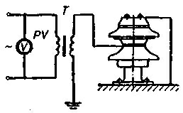
Figure 8 - Schematic diagram of the test of the support insulator with increased voltage 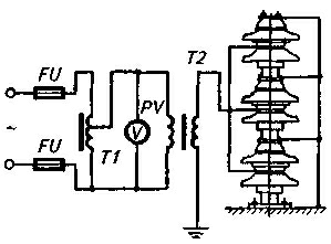
Figure 9 - Schematic diagram of testing several insulators of a suspension garland with increased voltage:
T1 - autotransformer; T2 - step-up transformer
The test voltage of the cell equipment is:
- for switchgear with a voltage of 6 and 10 kV, respectively, 32 and 42 kV;
- for outdoor switchgear with voltage 10; 35 and NO kV, respectively 47; 110 and 295 kV.
The test can be carried out simultaneously on all three phases relative to earth with the circuit breaker closed according to this scheme. 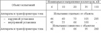
Table 3 - Test voltages of insulators, kV
Test object Rated voltage of insulators, kV
6 10 20 35 110
Devices and current transformers Tests separately from the object
- outdoor installation 46 60 73 105 285
- indoor installation 42 55 66 100 -
Tests together with the object
Apparatus and current transformers 42 55 66 95 260
If the cell contains a single-tank oil circuit breaker, then each phase should be tested with the other two phases grounded and the phase-to-phase insulation of the oil circuit breaker should be tested simultaneously.
If the panel is disconnected from the busbars for testing, but the busbars are energized at the time of the test, the air insulation distances between the blades and jaws of the disconnected busbar disconnector must be observed.
High voltage tests of support and suspension insulators can be performed for each insulator separately (Figure 8) or for several insulators simultaneously (Figure 9). The value of the test voltage applied to each element of the pin insulator and suspension string must be 50 kV.
The norms for AC test voltages for bushing type insulators, as well as for single-element post insulators, are given in table 3.
To detect defects in suspension and support insulators of substations under operating conditions, the voltage distribution over the insulation is measured using a special rod. The method is based on measuring the voltage that falls on each insulator of a garland (column) or on each element of the insulator. For each garland consisting of insulators of the same type, and for each type of insulator consisting of individual elements, the distribution of the operating voltage is quite definite. If there is a defective insulator in a string or column, the voltage distribution changes dramatically. The insulator must be replaced if the value of the voltage attributable to it, measured by the rod, has decreased in comparison with the voltage attributable to a suitable insulator by 1.5 ... 2 times.
The technique for testing insulation with direct current is similar to the technique for testing with alternating current, however, the leakage current is additionally controlled. The strength of the current passing through the insulation when tested with direct current, in most cases, does not exceed 5 ... 10 mA, which causes a small power of the test transformer. DC insulation test is carried out using special test apparatus AKI-50, AIIM-70 and AIIM-72.
The main control over the state of the arrester is the annual measurement of its conduction current and breakdown voltage. A sharp decrease in the conduction current strength indicates an open circuit of the shunt resistances, and its sharp increase indicates dampness of the ceramic shunt resistances as a result of moisture penetration into the cavity of the arrester (violation of sealing).
According to the Rules for the installation of electrical installations, the test voltage for arresters RVS-3, RVS-6, RVS-10 and RVS-30 is 4, respectively; 6; ten; 24 kV, and for arresters of the type RVP-3, RVP-6 and RVP-10 - respectively 4; 6 and 10 kV.
Preventive testing of switchgear devices is carried out in the following terms:
a) oil circuit breakers and their drives, as well as drives remote control disconnectors - simultaneously with the overhaul, and oil-filled tank measuring transformers - at least once every 6 years;
b) concrete reactors, coupling capacitors, static capacitors - at least once every 3 years;
c) pin insulators (6 ... 10 kV) of busbar bridges, as well as ShT-35 insulators - at least once a year; pin insulators ISHD-35 and OS-1 - at least once every 3 years; other devices (arresters) and suspension insulators - at least once every 6 years;
d) contacts of bus connections and connections to equipment - at least once every 4 years;
e) spare electrical equipment, spare parts and parts - at least once every 3 years.
If there are defects in the equipment, the periods between tests are reduced and additionally determined technical manager enterprises.
Preventive testing of electrical equipment is mainly reduced to insulation testing and measurement transitional resistances contacts of various equipment. Preventive testing of insulation under operating conditions is necessary in order to identify defects that cannot be detected by external inspection. These defects do not disrupt the normal operation of the equipment, but in the future they can lead to an accident in the installation. Preventive tests in order to check the condition of the insulation are subjected to support and bushing insulators, linear bushings, hardware insulators of disconnectors and fuses, switches, instrument transformers, arresters, etc. The scope of insulation tests includes: measurement of insulation resistance, dielectric loss tangent, force value leakage current and overvoltage test.
Tests and measurements in electrical installations are carried out before they are accepted into operation within the time limits determined by the frequency of preventive tests, as well as during major and current repairs electrical equipment.
Carrying out acceptance tests in electrical installations is regulated by GOST R 50571.16-99 "Electrical installations of buildings, Part 6. Tests, Chapter 61. Acceptance tests", as well as the Rules for Electrical Installations, Chapter 1.8. "Norms of acceptance tests".
Acceptance tests and measurements in electrical installations represent a whole range of works. These works include:
- testing and measurements in electrical installations;
- drawing up a technical report and other necessary documentation;
- obtaining and approval in Rostekhnadzor of the permit of the electrical installation for operation.
The main stages of measuring work in electrical installations
1. Visual inspection of the state of the electrical facilities of the facility.
When expanding or reconstructing an existing electrical installation, it is necessary to make sure that its expansion or reconstruction meets the requirements of the GOST R 50571 set of standards and does not reduce the safety of the existing part of the electrical installation. Visual inspection should precede the test and be carried out both with the electrical installation completely disconnected and in operating mode.
2. Measurement of current spreading resistance of grounding devices and ground electrodes.
Grounding devices must comply with the requirements state standards, rules for the installation of electrical installations, building codes and regulations and other regulatory and technical documents, ensure the safety of people, operating modes and protection of electrical installations (PTE EP Ch.2.7.p.2.7.2).
3. Checking the presence of a circuit between the grounding and grounding elements.
This test is carried out in accordance with GOST 12.1.030-81 in order to ensure electrical safety by checking the correct connection and integrity of all protective conductors, grounding conductors, protective earthing, potential equalization.
According to the results of measurements by the electrotechnical laboratory, the following is determined:
- safety of operation of the electrical equipment installed and connected to the power grid;
- continuity of protective conductors grounding stationary (if necessary, portable or mobile) electrical equipment or devices;
- absence of dangerous potentials on grounded electrical equipment elements.
4. Measurement of insulation resistance of wires and cables.
The insulation resistance of electrically conductive lines with voltage up to 1000V must be at least 0.5 (1.0) MΩ. (PTE EP Table 6, clause 6.2, Appendix No. 3 PTE EP). According to the results of measurements by the electrotechnical laboratory, the following is determined:
- suitability of electrically conductive lines for safe operation;
- suitability of inductive consumers for technological suitability and for safe operation.
5. Checking the coordination of the parameters of the "phase - zero" circuit with the characteristics of protection devices and the continuity of protective conductors.
The object of measurement is the circuit "phase-zero", "phase-ground" and "phase-phase" in electrical installations with voltage up to 1000V with a solidly grounded neutral, their impedance. The measured value is the impedance of the phase-zero circuit. Verification of protection measures against indirect contact is carried out during acceptance and operational tests in accordance with the requirements of the PUE, p.p. 1.7.78, 1.7.79.
6. Checking and testing of circuit breakers controlled by differential current.
The object of measurements are residual current devices (RCDs) and circuit breakers, including differential protection in electrical installations with voltage up to 1000 V. According to the measurement results, depending on the task, the electrical laboratory determines:
- touch voltage;
- differential protection operation time;
- operating current of differential protection.
7. Checking the correct phase sequence.
Most three-phase consumers require a certain phase rotation in a three-phase power supply system and can be damaged if it is disturbed. Based on the results of measurements, the electrical laboratory determines the order of phase sequence in the connections of input, distribution and group electrical panels and current collectors.
8. Measurements of supply voltage, current consumption and frequency.
When data is needed electrical network the electrical laboratory produces these measurements in input devices, power and distribution electrical panels.
9. Measurement of illumination.
If it is necessary to obtain data on illumination, the electrical laboratory makes appropriate measurements, both indoors and outdoors.
10. Checking automatic switches with voltage up to 1000V.
The object of measurements are circuit breakers that serve to protect AC distribution networks and power receivers in emergency cases in case of damage to the insulation, the occurrence of overload currents and short circuits. According to the results of measurements by the electrotechnical laboratory, the following is determined:
- the time of operation of the releases of the installations of protection against short-circuit currents;
- time of operation of releases of overcurrent protection installations.
Based on the results of the measurements, a technical report is drawn up, consisting of a set of relevant protocols. In each protocol, a conclusion is given on the compliance of the measurement results with the current norms and rules, there are notes and conclusions. All comments on visual inspection and the measurements taken are recorded in the defective statement of the technical report. The defect list contains recommendations for eliminating defects, comments and deviations from regulatory requirements.
When measuring and testing, the electrical laboratory uses measuring equipment of domestic and foreign production, included in State Register measuring instruments of Russia and passed the state check. Measurements, data analysis and compilation technical documentation in the prescribed form is produced by qualified engineering and technical personnel of the laboratory. The personnel involved in the work has individual certificates of advanced training in the field of testing and measurements in electrical installations up to 1000V and certificates for checking knowledge of current norms and rules in the field of electrical safety. Operational-repair and administrative-technical personnel undergo a knowledge test in the services of ROSTEKHNADZOR, each specialist has an electrical safety clearance group of at least IV.
The cost of testing
The cost of testing depends on the functional purpose of the premises, its area, the number of test points, etc. etc. I would like to draw your attention to the fact that our company does not provide a package of documents without testing, since during the identified defects it is possible to avoid fires in electrical wiring.
The average cost of work on measurements is on average from 18,000 rubles. We will be able to determine the exact cost of the work after receiving terms of reference, indicating the number of tested points.
To order testing from us, you just need to call one of our phones or fill out an On-line application.
Advantages of cooperation with Alfa Service Group
Alfa Service Group LLC has its own registered electrical laboratory (registration No. 4206 dated September 30, 2011). Testing equipment undergoes annual state verification.
Our experts have extensive experience, apply modern equipment, work professionally and promptly, so you can be sure of the quality and reliability of the work of Alfa Service Group.
It is most profitable to order the services of an electrical laboratory in a complex of other services to ensure fire safety object, since in this case a flexible system of discounts works, and our offer will be economically attractive for you.
We also recommend
 What is the name of the amount of money at stake in the game Modern monetary system is a financial pyramid
 How to name a horse: we select a suitable nickname
 How to name a horse: we select a suitable nickname
 Point of the celestial sphere above the observer's head
 Common peacock (Indian)
 What is the name of the male and female