What is checked by pneumatic tests. Pipeline Strength and Leak Testing Program - Maximum Pressure
GOU SPO "Chelyabinsk State Industrial and Humanitarian College named after V.I. Yakovleva A.V.”
Control robot
By discipline: "Quality control of welded structures"
Topic: "Pneumatic and mechanical tests"
Completed:
Rudnev V.A.
Course V group 505z
Supervisor:
Panafidina G.V.
Form of study: part-time
Use the appropriate tools and materials for the activity being performed. taking into account all preventive measures for their implementation. A. Notify and inform Inspector C. Attend courses. Maintain a motivational interest in the safety of employees. Recording and reporting of incidents during the performance of work. which reflects safe and effective methods and procedures for performing assigned actions. Consideration of safe working conditions. Coordinate and direct the various activities of the procedure.
The head of the chauffeur's department responsible for business trips during the emergency relocation. taking into account the safe conditions of transmission. The planner and field supervisor of the risks to which workers are exposed. Be alert to the need for a field supervisor in terms of tools or materials to be used during the activity to leave the company vehicle parked.
Chelyabinsk 2009
Introduction
1. Mechanical tests
2. Pneumatic testing
Bibliography
1. Mechanical tests
Destructive methods of control of welded joints. Destructive control methods include methods for testing control samples in order to obtain required characteristics welded joint.
O. subject to safe conditions. Perform an unlimited work permit in the locality. Personnel participating in this activity must obtain a folder from the supervisor which must contain the following precautions: Pneumatic Test Registration Format and Isometric Plans. Review of the availability of properly certified tools and equipment to be used in the workplace. in good condition and suitable for the activity to be carried out. before disclosure and signature of all personnel. 12 Zone Manager 2. Provision of funds personal protection.
These methods can be used both on control samples and on segments cut from the joint itself. As a result of destructive control methods, the correctness of the selected materials, selected modes and technologies is checked, and the qualification of the welder is assessed.
Mechanical testing is one of the main methods of destructive testing. According to their data, it is possible to judge the compliance of the base material and the welded joint with the technical specifications and other standards provided for in this industry.
Personnel involved in this activity must be fully informed of the risks associated with each activity and at the same time suitable for its implementation. Sequence of actions during the performance of tightness tests. in case of pressure contained in the compressor tank. Close the free ends of the pipe to be checked. proceed with the following actions: Dispose of personal protective equipment. Have workers with sufficient experience and proven experience in performing their duties.
Planner Planner Planner 3 Check compressor availability and certificates. Examine the joints. to check their status. Ensure the good physical and health status of employees. As soon as indicated by the planner. C. Coordinator 4 Paramedic 5 Resident Engineer. among other things. Keep communication channels free and available sooner.
Mechanical tests include: testing of a welded joint as a whole in its various sections (deposited metal, base metal, heat-affected zone) for static (short-term) tension;
static bend;
impact bending (on notched specimens);
for resistance to mechanical aging;
Make sure the air supply is correct and continuous. up to 100% of compressor capacity and run pressure until reaching 100 psi. If the pipe is not leaking, continue depressurizing after the test is complete. Continue filling out the registration report. When the network has more than one connection point. The recorder disk will be parsed and the result will be compared with a dot. The air injection valve will open to relieve pressure. Model. after repair, all tests must be repeated.
The pressure gauge is read at 1 hour intervals during the working day to check the behavior. If a leak is detected. marking and measuring range and control head. if there are no signs of leakage or otherwise unsatisfactory. The trial area will be cordoned off and warning bulletins will be posted. Once the testing period is completed and approved stakeholders. Test pressure. the same should be placed with a soapy water solution. Signatures of the client, among others.
metal hardness measurement different areas welded joint.
Control samples for mechanical testing are welded from the same metal, by the same method and by the same welder as the main product.
In exceptional cases, control samples are cut directly from the controlled product. Sample options for determination mechanical properties welded joint are shown in Figure 1.
Start recording pressure with equipment for this purpose. Connect the pressure compressor hose to the free end valve of the test device. pneumatic test devices will be dismantled. Close the valve used for air injection and disconnect the air source. close the free ends of the pipes, leaving only the compressed air injection connection, setting the test device with a calibrated recorder and pressure gauge. To: Provision and use of personal protective equipment is mandatory.
Figure 1. Variants of samples for determining mechanical properties (dimensions in mm): A-B - for tension of the deposited metal (A) and welded joint (B); B - for bending; G - impact strength.
Static tension tests the strength of welded joints, yield strength, relative elongation and relative narrowing. Static bending is carried out to determine the plasticity of the connection by the magnitude of the bending angle before the formation of the first crack in the stretched zone. Static bending tests are carried out on samples with longitudinal and transverse welds with the weld reinforcement removed, flush with the base metal.
It will also be posted if the work is not completed. Evacuate the area to prevent further injury and allow access to trained personnel. mask. It also includes the next steps in the event of a fire and an emergency plan. fractures. Steps to follow: Report the accident to your line manager working area. An emergency situation can be caused by the following reasons: fire. to prevent the intrusion of third parties into working area. Disclose related risk control procedures. nineteen.
Impact bending is a test that determines the impact strength of a welded joint. According to the results of hardness determination, one can judge about strength characteristics, structural changes in the metal and the stability of welds against brittle fracture. Depending on the specifications the product may be subject to impact rupture. For small diameter pipes with longitudinal and transverse seams, flattening tests are carried out. The measure of plasticity is the gap between the pressed surfaces at the appearance of the first crack. Metallographic studies of welded joints are carried out to establish the structure of the metal, the quality of the welded joint, and identify the presence and nature of defects. By the type of fracture, the nature of the destruction of the samples is established, the macro- and microstructure of the weld and the heat-affected zone are studied, and the structure of the metal and its plasticity are judged.
Conduct inspections and periodic Maintenance tools and working equipment. Clean the place where the victim should give him more ventilation. has an emergency plan. Maintain calm and control over the situation. stretcher.
This plan includes a procedure that determines the actions to be taken in the event of a emergency during the execution of work. Move the victim immediately to the nearest medical Center. In case of fire: Available resources: 10 lb. dry chemical fire extinguishers.
Macrostructural analysis determines the location of visible defects and their nature, as well as macrosections and fractures of the metal. It is carried out with the naked eye or under a magnifying glass with a 20x magnification.
Microstructural analysis is carried out with a magnification of 50-2000 times using special microscopes. With this method, it is possible to detect oxides at the grain boundaries, metal burnout, particles of non-metallic inclusions, the size of metal grains and other changes in its structure caused by heat treatment. If necessary, make a chemical and spectral analysis of welded joints.
Prepare reports and complete required information in formats for this purpose. In case of impossibility to control the situation. Objective: To mobilize personnel immediately if possible during this procedure. Access routes and emergency routes: The access route and escape routes are indicated in the sketches of the escape route. to take the appropriate action that deserves it. Steps: In case of fire. Ambulance will be available with first aid supplies. 21.
Employees will receive instructions from field supervision of the work. in such a way that it will continue to report. Specific eviction plan: Purpose: This plan establishes necessary actions to control all personnel during the hour of an emergency in order to avoid harm to personnel. Logistic support: in case of situations that merit the transfer of personnel to the medical center. Use dry chemical powder fire extinguishers 10 lb capacity. Scope of application: Understands all personnel involved in this procedure. evacuate the area immediately. to the environment.
Special tests are performed for critical structures. They take into account the operating conditions and are carried out according to the methods developed for this type of product.
2. Pneumatic testing
Pneumatic tests in cases where it is not possible to perform hydraulic tests. Pneumatic tests involve filling the vessel with compressed air at a pressure exceeding atmospheric pressure by 10-20 kPa or 10-20% higher than the working one. The seams are moistened with soapy water or the product is immersed in water. The absence of bubbles indicates tightness. There is a variant of pneumatic testing with a helium leak detector. To do this, a vacuum is created inside the vessel, and outside it is blown with a mixture of air and helium, which has exceptional permeability. The helium that has got inside is sucked off and falls on a special device - a leak detector that fixes helium. By the amount of helium trapped, the tightness of the vessel is judged. Vacuum control is carried out when it is impossible to perform other types of tests.
The strategy of this plan is to deal with emergencies in order to protect the physical integrity of the staff and external organs of workers associated with the work they perform. Or with the objects involved in the operation. Rationale: due to the complexity of the work performed. Stretching. The route to be used is shown schematically in any case. What are the evacuation routes? move the area. Only personnel participating in the plan will be allowed access to this area.
This vehicle will remain at the work site while the work is being done. This is expected to control emergency actions or other natural phenomena which may interfere with normal workflow. Procedures: after notification of a fire. Or until an emergency is filed. 22. Walter Flores. Flight owner.
The tightness of the seams can be checked with kerosene. To do this, one side of the seam is painted with chalk with a spray gun, and the other side is moistened with kerosene. Kerosene has a high penetrating ability, therefore, with loose seams, the reverse side is painted in dark tone or spots appear.
Compressed air test (pneumatic test). This test is used to test vessels and pipe wires for tightness, as a rule, only at the working pressure of the product. The density of welded joints is checked with a soapy solution or by immersing the vessel in water. Bubbles appear in places where gas passes.
Maintain calm and control over the situation. Pneumatic pipes require strict safety measures. Pneumatic testing is a procedure that uses air pressure to test leak pipes. This method not only serves to detect leaks, but also to clean and dry the piping system, allowing the conveyor to be ready at the end of the test. The pneumatic test is used when other methods are not possible; for example, in the case of freezing, the water test is not possible.
When the test continues, all station personnel must move away from the test site. Personnel involved in the task must be located behind the security barrier and the site must be designated as a hazardous area. Heavy traffic areas and pedestrians must be notified in advance before taking the test. Leaks or ruptures during testing can result in property damage or serious injury. Before testing, all piping in the test section must be checked to ensure that no movement occurs.
External inspection is the most common and affordable type of control that does not require material costs. All types of welded joints are subjected to this control, despite the use of further methods. An external examination reveals almost all types of external defects. With this type of control, it is not penetrations, sagging, undercuts and other defects that are visible that are determined. External examination is performed with the naked eye or using a magnifying glass with a 10x magnification. External inspection includes not only visual observation, but also measurement of welded joints and seams, as well as measurement of prepared edges. In mass production, there are special templates that allow you to measure the parameters of welds with a sufficient degree of accuracy.
Before testing begins, personnel should also ensure that all test connections are properly installed, final shut-off valves are stable, filling in place and sealing, and welds have been cooled. Test personnel must wear eye and ear protection.
The design engineer determines maximum pressure, which will be used in the test, and the pipeline being tested. The recommended test length should not exceed 400 feet. All openings that are not closed off by valves must be covered with a 150 lb. blind flange or other suitable cap. It is not necessary to connect all drains and ventilation grilles to the test, and also not to open all sectors that are not involved in testing to the atmosphere. The project manager determines the test opening pressure, which is typically 25 psi and held for a minimum of 10 minutes.
In the conditions of a single production, welded joints are measured with universal measuring tools or standard templates, an example of which is shown in Fig. 2.
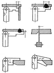
Rice. 2 Measurement of cutting edges, gaps and dimensions of seams with a ShS-2 template
A set of ShS-2 templates is a set of steel plates of the same thickness, located on axes between two cheeks. On each of the axles, 11 plates are fixed, which are pressed on both sides by flat springs. Two plates are designed to check the knots of cutting edges, the rest - to check the width and height of the seam. With this versatile template, you can check bevel angles, gaps, and weld dimensions of butt, tee, and fillet joints.
Leaks found during this phase of the test will cause the test to stop. The pressure will then be increased by 25 psi at five minute intervals. When the maximum pressure is reached, it is maintained for 10 minutes. Finally, the pressure is reduced to 100 psi and held for 24 hours. At this time, the pressure is removed, carefully around the exhaust, dirt and noise.
The design engineer determines appropriate place to submit forms. The pipeline is ready for use immediately after completion of the test. From pipes, valves and other accessories and connections. Thermal insulation materials. Sequential frictional force of pipe movements Forces due to thermal expansion.
The tightness of containers and vessels operating under pressure is checked by hydraulic and pneumatic tests. Hydraulic tests are with pressure, filling or watering. For the pour test, the welds are dried or wiped dry and the container filled with water so that no moisture enters the welds. After filling the container with water, all seams are inspected; the absence of wet seams will indicate their tightness.
Irrigation tests are subjected to bulky products that have access to the seams from both sides. One side of the product is poured with water from a hose under pressure and the tightness of the seams on the other side is checked.
In a hydraulic pressure test, the vessel is filled with water and overpressure, exceeding the operating pressure by 1.2-2 times. In this state, the product is kept for 5 to 10 minutes. Tightness is checked by the presence of moisture in bulk and the magnitude of the pressure drop. All types of hydraulic tests are carried out at positive temperatures.
Bibliography
1. Volchenko V.N. "Quality control of welding" - M: Mashinostroenie, 1995
2. Stepanov V.V. Welder's Handbook. Ed. 3 - e.M., "Engineering", 1974
Pneumatic testing of pipelines carried out to test them for strength and density or only for density. In the latter case, the pipeline must be preliminarily tested for strength by a hydraulic method. Ammonia and freon pipelines are not hydraulically tested for strength.
Pneumatic testing is supposed to be carried out with air or an inert gas, for which they use mobile compressors or factory compressed air network.
In exceptional cases, arising from the requirements of the project, it is allowed to carry out a pneumatic strength test of pipelines with a deviation from the data given in the table. In this case, the test must be carried out in strict accordance with a specially developed (for each case) instruction that ensures proper work safety.
Pneumatic strength test elevated cast-iron, as well as faolitic and glass pipelines is prohibited. In case of installation on steel pipelines cast iron fittings (except for ductile iron fittings), a pneumatic strength test is allowed at a pressure not exceeding 4 kgf / cm 2, while all cast iron fittings must pass a preliminary hydraulic test strength in accordance with GOST.
The pressure in the tested pipeline should be raised gradually, inspecting it when it reaches: 0.6 of the test pressure for pipelines with a working pressure of up to 2 kgf / cm 2; 0.3 and 0.6 of the test pressure for pipelines with a working pressure above 2 kgf / cm 2.
When inspecting the pipeline, an increase in pressure is not allowed. The final inspection is carried out at operating pressure and combined with a pipeline tightness test. At the same time, the tightness of welded joints, flange joints and glands is checked by coating them with a soapy or other solution.
Tapping a pipeline under pressure with a hammer is not allowed.
The results of the pneumatic test are considered satisfactory if during the strength test there was no pressure drop on the pressure gauge and during the subsequent tightness test, no leaks or gaps were found in the welds, flange joints and glands.
Pipelines transporting potent toxic substances and other products with toxic properties, liquefied petroleum gases, flammable and active gases, as well as flammable and combustible liquids transported at temperatures above their boiling point, subjected to further testing for density.
In this case, the test is carried out with the determination of the pressure drop. Shop pipelines transporting the products listed above undergo additional density tests together with the equipment to which they are connected.
The density test with the determination of the pressure drop can only be carried out after the temperatures inside the pipeline have equalized, for which thermometers should be installed at the beginning and end of the test section. The duration of tests of intershop pipelines for density with the determination of the pressure drop is established by the project; it must be at least 12 hours.
The pressure drop in the pipeline during its density test is determined by the formula:
DYA=10O / Rkon X Rnach
where DYa value of pressure drop, %;
Rcon and Rnach the sum of gauge and barometric pressures, respectively, at the end and beginning of the test, kgf/cm 2 ;
Tcon and Tnach are the absolute temperature of air or gas, respectively, at the end and beginning of the test, deg.
The pressure and temperature of air or gas in the pipeline is determined as the arithmetic average of the readings of all pressure gauges and thermometers installed on the pipeline.
An intershop pipeline with a conditional passage of 250 mm is recognized as having passed the additional test for. density, if the pressure drop in it for 1 hour as a percentage of the test pressure is not more than: 0.1 when transporting toxic products; 0.2 when transporting explosive, flammable, combustible and active gases (including liquefied ones).
When testing pipelines of other diameters, the fall rates in them are determined by multiplying the above figures by a correction factor.
For the duration of pneumatic tests, both indoors and outdoors, it is necessary to establish a protected area and mark it with flags. Minimum distance in any direction from the tested pipeline to the boundary of the zone: with above-ground laying 25 m, and with underground laying 10 m.
Control posts are set up to monitor the protected area. During the rise in pressure in the pipeline and when testing it for strength, it is not allowed for people to stay in the protected area, except for persons specially designated for this purpose and instructed. An act is drawn up for the results of pneumatic tests of the pipeline.
We also recommend
 Hero pioneers in the Great Patriotic War Heroes of the Patriotic War pioneers presentation
 Presentation "Formation of posture in preschool children Hygiene of correct posture presentation for children
 Sciences of the human body
 Presentation "history and prospects for the development of robotics"
 The value of the struggle of Russia with the Polovtsy
 Asia and Africa after World War II