The order of calibration of measuring instruments at the enterprise. calibration procedure. Information about the state of production facilities
RD 153-34.0-11.205-98
METHODOLOGICAL INSTRUCTIONS.
MEASURING CHANNELS OF INFORMATION-MEASURING SYSTEMS.
ORGANIZATION AND PROCEDURE FOR CALIBRATION
Introduction date 2000-11-01
DEVELOPED by the Open Joint Stock Company "Firm for the adjustment, improvement of technology and operation of power plants and networks ORGRES"
PERFORMERS A.G. Azhikin, S.A. Sporykhin, V.I. Osipova
APPROVED by the Department of Development Strategy and Scientific and Technical Policy of RAO "UES of Russia" on 10.06.98
First Deputy Head A.P. Bersenev
These Guidelines apply to the measuring channels of information-measuring systems - IC IIS (hereinafter - IC), establish requirements for methods and means of calibration; determine the organization, procedure for carrying out and registration of calibration results; regulate the algorithms for determining the metrological characteristics (MX) of the MC during calibration and are intended for the metrological services of energy enterprises accredited for the right to carry out work on the calibration of the MC of the IMS.
Methodical instructions are developed according to the Law of the Russian Federation " " , GOST 8.438-81 , PR 50.2.016-94 and RD 50-660-88 .
In accordance with these Guidelines, guidelines for MC calibration for specific types of IMS should be developed.
With the release of these Guidelines, the "Methodology. Measuring channels of information-measuring systems. Organization and procedure for verification: RD 34.11.205-88" (M.: SPO Soyuztekhenergo, 1988) becomes invalid.
1. GENERAL PROVISIONS
1.1. The purpose of calibration is to determine and confirm the actual values of MX and (or) suitability for the use of IC, which are not subject to state metrological control and supervision.
1.2. IR calibration must be carried out as a set (complete method).
If the calibration cannot be carried out by the complete method, then it is carried out element by element (element by element method).
The elements of IC IIS are understood as separate measuring instruments (SI) or sets of SI and other technical means, including communication lines used in IC IIS.
When performing element-by-element calibration, the primary measuring transducer (PMT) (or PMT and MT) and the electrical path of the IC (ET IC) are calibrated separately. Calibration of the ET IC is carried out in accordance with the procedure described in these Guidelines.
1.3. All MCs are calibrated at the intervals specified in the certificate of metrological attestation (MA).
1.4. The list of MCs to be calibrated is compiled by the metrological service of the power enterprise and approved by the chief engineer.
1.5. IMS measuring channels subject to state metrological control and supervision, in accordance with Art. 13 of the Law of the Russian Federation "On ensuring the uniformity of measurements" must be subjected to periodic verification.
The list of MCs to be verified is compiled by the metrological service of the power enterprise and sent to the territorial body of the State Standard of Russia.
Verification of IC is carried out according to the methodology approved by the State Metrological Service, or according to the methodology set out in these Guidelines and agreed with the territorial body of the State Standard of Russia.
Verification intervals are established by the territorial body of the State Metrological Service. Adjustment of calibration intervals is carried out by the body of the State Metrological Service in agreement with the metrological service of the power enterprise.
2. CALIBRATION OPERATIONS
During calibration, the following operations must be performed:
availability check technical documentation on IMS and aggregate measuring instruments (ASI) included in the IC (appendix);
determination of metrological characteristics (section );
results processing experimental studies(section );
registration of calibration results (section of these Guidelines).
3. CALIBRATION TOOLS
3.1. Means of calibration (standards) must ensure the reproduction and (or) storage of units physical quantity with the highest accuracy in order to transfer its IC value from the relevant state standards, and also have a valid calibration (verification) stamp or calibration (verification) certificate.
3.5. Control over external conditions should be carried out by MI, the absolute value of the error of which is not more than 0.1 of the change in the value of the external influencing quantity, at which additional errors arise for the MI that are part of the MI.
instructing the personnel involved in the calibration;
prepare calibration tables for thermoelectric converters and resistance temperature converters, tables of calculated values of pressure drops for IR flow and level (an example of a table is given in Appendix);
prepare and install standards and auxiliary MI to set the input signal and control the influencing quantities;
establish communication (by radio or telephone) from the means of setting the input signal to the means of presenting information.
7. CALIBRATION
7.1. Visual inspection
7.1.1. When conducting an external examination of the IC, it is necessary to check:
completeness of IC;
serviceability of ASI seals;
correctness and quality of shielding, installation of communication lines;
the absence of mechanical damage and defects of the ASI, which are part of the IC, which may affect their performance;
performance of grounding of the ASI, which are part of the MC, in accordance with the requirements of the operating instructions or technical descriptions for specific ASI;
presence of marking of communication lines.
7.1.2. If the IC does not comply with the above requirements, calibration is not carried out until the identified deficiencies are eliminated.
7.2. Checking the functioning of the IC (testing)
The functioning of the MC under operating conditions is checked by displaying the values of the measured value of the technological parameter on the means of presenting information. If the value of the measured parameter corresponds to the operating mode of the equipment, then it is considered that the IR is functioning normally.
7.3. Determination of metrological characteristics
7.3.1. Determination of the number of points under study by the IR measurement range
The studied points are set in accordance with the MA IK IIS program in an amount of at least 5.
The points under study are evenly spaced over the entire IR measurement range, with one point corresponding to 0% and the other to 100% of the range.
If it is impossible to investigate the points of 0% and 100%, then they are replaced by points at which the actual values of the measured parameter are determined by the formulas:
|
X u0 = X 0 + |Δ l| + |Δh|; |
|
|
X u100 = X 100 - |Δ l| - |Δh|, |
where X u0 and X u100 - actual values of the measured parameter at the points under study, located near the lower and upper limits of the IR measurement range;
X 0 and X 100 - lower and upper limits of the IR measurement range;
Δ l and Δh - the lower and upper limits of the confidence interval of the IC measurement error, indicated in the certificate of MA IC IMS.
7.3.2. Conducting experimental studies
7.3.2.1. With the complete method, experimental work consists in determining the values of the MC output signal at each investigated point in the MC measurement range and monitoring the operating conditions of the MC.
The scheme of the experiment is presented in the appendix (Fig. ).
7.3.2.2. With the element-by-element method, experimental work consists in determining:
maximum values absolute error PIP (or PIP and IP) at the points under study according to the calibration protocol, while the following condition must be met:
ΔPIPmax ≤ ΔPIPd;
ΔIPmax ≤ ΔIPd,
where ΔPIPd is the maximum allowable value of the PIP error specified in the NTD;
ΔIPd - the maximum permissible error value of the IP specified in the NTD,
values of the output signal of the ET IC at the points under study and control of its operating conditions, as well as the values of external influencing quantities for PIP (or PIP and IP). Structural scheme the experiment is shown in fig. .
7.3.2.3. Three observations are made at each point under study.
7.3.2.4. Registration of the results of observations is carried out at intervals of time equal to the polling cycle of the PIP or exceeding it.
7.3.2.5. The results of experimental studies are recorded in table. 1 and 2 protocols (applications and).
7.3.2.6. The standards are connected in accordance with the NTD for ASI.
7.3.2.7. After the experimental work, the working circuit of the IC is restored and its operation is checked (see section ).
7.4. Processing the results of experimental studies
7.4.1. Processing the results of experimental studies consists in determining the error of the MC.
7.4.2. Processing of the results of experimental studies is carried out according to the algorithm.
7.4.2.1. The error of the IR for each i-th observation at the j-th point under study is determined by:
with the complete method according to the formula
where X ji - i-th value of the parameter from the protocol of experimental studies (measured value at the j-th point under study) in units of the measured value;
X gi - the actual value of the parameter in j-th point, corresponding to the set value by the master-standard (set by the master and measured by the reference);
i - observation number at the j-th point (i = 1, 2, 3);
with the element-by-element method according to the formula
where ΔPIPmaxj is the maximum value of the absolute error of the PIP at the j-th point;
ΔIPmaxj - the maximum value of the absolute error of the MT at the j-th point;
l- the number of influencing quantities ( l = 1...m).
7.4.2.2. The average values of the errors of the MC at the j-th point under study are determined (with the complete and element-by-element methods) according to the formulas:
where is the average value of the IC error for three observations;
And - the average value of the error of the IC for the two largest and two smallest values;
Δjimin and Δjimax are the minimum and maximum error values at the j-th point under study, respectively.
7.4.3. Conclusion on the suitability of the IC.
7.4.3.1. The conclusion is made according to the algorithm shown in Fig. .
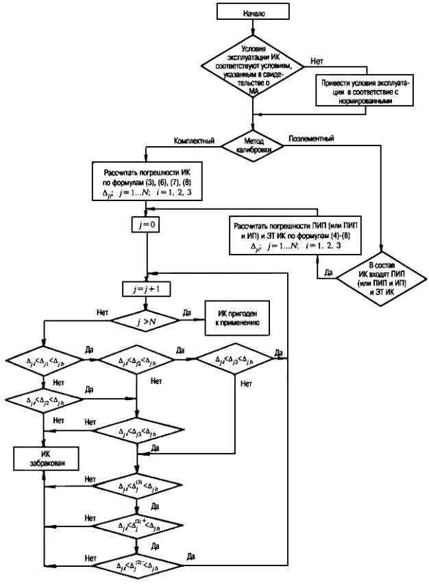
Rice. 1. Block diagram of the algorithm for determining the suitability of IC for use
7.4.3.2. The measuring channel is considered suitable for use based on the calibration results if:
operating conditions of the IC correspond to the conditions specified in the MA certificate;
at all points of the IR measurement range, the error values calculated by one of the formulas (), () or () satisfy the inequality
or at least two error values calculated by one of the formulas (), () or (), satisfy the inequality () provided that the inequality is fulfilled
and one of the inequalities:
|
Δ l < Δ(2)+ < Δh |
|
|
Δ l < Δ(2)- < Δh |
8. PRESENTATION OF CALIBRATION RESULTS
Based on the calibration results, a certificate of calibration of the IC IMS is issued in the form given in the Appendix.
Based on the verification results, a certificate of verification of the IC IIS is issued in the form given in the Appendix.
Attachment 1
Mandatory
LIST OF TECHNICAL DOCUMENTATION TO BE PRESENTED DURING THE IR CALIBRATION
1. Technical description of IIS.
2. Operating instructions for IMS.
3. Guidelines for the calibration of IC IMS.
4. Methods of calibration or verification.
5. Certificate and protocol of the last IR calibration.
6. Certificate of MA IK IIS.
7. List and values of MX elements of IIS, technical description on ASI, a magazine about the calibration of ASI.
8. Program MA IK IIS.
Appendix 2
STANDARDS AND AUXILIARY SI USED
WHEN CALIBRATING
|
Name |
Measuring range |
Basic error, % |
Purpose |
|
|
1. Oil press |
Upper measurement limit 6 kgf/cm2 (0.6 MPa) |
Setting the input signal for the complete IR pressure calibration method |
||
|
2. Reference pressure gauge |
Control of the input signal with the complete IR pressure calibration method |
|||
|
3. Exemplary deformation pressure gauge |
Upper measurement limit 1 kgf/cm2 (0.1 MPa) |
|||
|
4. Pressure gauge |
Air 250 |
Upper measurement limit 250 kgf/cm2 (25 MPa) |
Setting the input signal for the complete calibration method of IR pressure, differential pressure |
|
|
5. Pressure vacuum gauge |
Upper measurement limit 2.5 kgf/cm2 (0.25 MPa) |
Setting the input signal for the complete IR vacuum calibration method |
||
|
6. Resistance shop |
(0.01 ÷ 111111.1) Ohm |
Setting the input signal for the element-by-element method of IR temperature calibration |
||
|
7. Potentiometer direct current |
||||
|
8. Mutual inductance store |
(5 10-4 ÷ 11.111) mH |
Setting the input signal for the element-by-element method of IR calibration of pressure, flow, level |
||
|
9. Source of electrical signals |
||||
|
10. Digital voltammeter |
Control of the input signal value in the element-by-element method of IR calibration of pressure, flow, level |
|||
|
11. Laboratory thermometer |
Scale division 1 °C |
Ambient temperature measurement |
||
|
12. Barometer |
(80 ÷ 106) 1000 Pa |
Barometric pressure measurement |
||
|
13. August psychrometer |
Scale division 0.5 °С |
Ambient humidity measurement |
||
|
14. Ammeter voltmeter |
Supply voltage measurement |
|||
|
15. Frequency meter |
(10 ÷ 1000) Hz |
±(1.5 10-7Hz + 1 count) |
Frequency measurement |
|
|
16. Vibration measuring device |
(12 ÷ 200) Hz |
Vibration measurement |
Appendix 3
EXAMPLE OF A CALIBRATION CHART FOR A MEASURING CHANNEL
TEMPERATURES USING THERMOELECTRIC
TRANSMITTER TYPE THA WITH MEASUREMENT RANGE FROM 0 TO 150 °C
|
Explored points |
Input signal value, mV |
|||||||||||||||
|
Free ends temperature, °C |
||||||||||||||||
Appendix 4
Reference
EXAMPLES OF THE STRUCTURAL SCHEMES OF THE EXPERIMENT
IN IR CALIBRATION
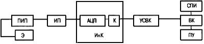
Rice. P4.1. Structural scheme of the experiment when calibrating the IR by the complete method:
PIP - primary measuring transducer (sensor); IP - measuring transducer;
ADC - analog-to-digital converter; K - switch; USVK - communication device with computer
complex; SPI - a means of presenting information; VK - computer complex;
PU - printing device; E - standard calibration tool; InK - information complex
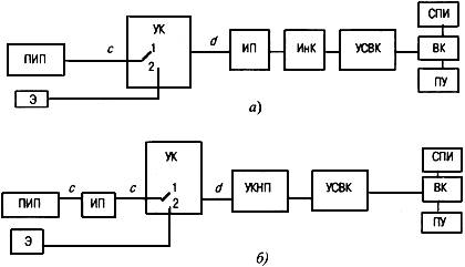
Rice. P4.2. Structural scheme of the experiment when calibrating the IC by the element-by-element method:
a - exemplary signal is fed to the input of the IP; b - exemplary signal is applied to the input of the UKNP;
UK - switching device;
UKNP - device for switching, normalization and conversion;
c, d- communication line between PIP and ET IC; 1
- working condition IR; 2
- calibration
For other designations, see fig. .
Annex 5
PROTOCOL
CALIBRATION IR COMPLETE METHOD
Table 1
|
Measured parameter |
Measuring range |
Calibration conditions |
Input signal value in |
The value of the output signal (measurement error) in units of the measured value |
Signature, number |
||||||||
|
% of measuring range |
units of measured quantity Xgi |
||||||||||||
Appendix 6
PROTOCOL
IR CALIBRATION BY ELEMENT METHOD
Table 1
|
Measured parameter |
Measuring range |
IR element |
IR error |
Calibration Conclusion |
Calibration Specialist (full name) | ||||||||||||
FOREWORD
1. DEVELOPED BY FSUE"Central Order of the Badge of Honor" Research Institute of Geodesy, Aerial Photography and Cartography. F.N. Krasovsky (FGUP TsNIIGAiK)
Director of the Institute N.L. Makarenko
theme leader,
Head OSMOGI A.I. Spiridonov
5. INTRODUCED FOR THE FIRST TIME
STO-02570823-8.03-05
INDUSTRY STANDARD
Introduction date 2005-10-01
1 . Application area
Law Russian Federation"On Ensuring the Uniformity of Measurements";
GOST 8.395-80 GSI. Normal measurement conditions during verification. General requirements;
OST 68-14-99 Types and processes of geodetic and cartographic production activities. Terms and Definitions;
PR 50.2.016-94. GSI Requirements for the performance of calibration work;
PR 50.2.017-95. CSI Regulations on the Russian Calibration System;
PR 502.018-95, GSI The procedure for accreditation of metrological services of legal entities for the right to carry out calibration work.
3 . Terms and Definitions
The following terms are used in this document with their respective definitions:
3.1 calibration of the measuring instrument (calibration work): A set of operations performed to determine and confirm the actual values of metrological characteristics and (or) suitability for use of measuring instruments that are not subject to state metrological control and supervision.
3.2 means of calibration: Standards, settings and other measuring instruments used in calibration, recognized as suitable for this purpose in accordance with established rules.
3.3 quality of calibration of measuring instruments: A set of calibration characteristics that determine the compliance of methods, means and conditions with the requirements established in the regulatory documents for calibration.
3.4 normative document (ND) for calibration: A document defining the organization and procedure for MI calibration and (or) methods and means of calibration.
4 . General provisions
4.1. Calibration of measuring instruments is carried out in accordance with the provisions of the Law of the Russian Federation "On ensuring the uniformity of measurements" and the metrology rules of the state system for ensuring the uniformity of measurements (GSI).
4.2. In accordance with Article 13 of the law "On Ensuring the Uniformity of Measurements", geodetic work belongs to the field state control and supervision, as a result of which measuring instruments used in geodetic works, of the types specified in OST 68-14, are subject to verification. In other cases, the measuring instruments used are subject to calibration.
4.3. Calibration is carried out by metrological services of enterprises and organizations of Roskartografii.
At the request of the Customer of works and in case of MI calibration for third-party needs, metrological services of enterprises and organizations of Roskartography can be accredited in accordance with PR 50.2.017 and PR 50.2.018. In this case, they will be given the right to issue calibration certificates on behalf of the bodies and organizations of the Gosstandart of Russia that accredited them. To obtain the right to perform calibration work, the requirements specified in section 5 must be met.
5 . Requirements for performing calibration work
5.1. In the Roskartography system, photogrammetric, cartographic and other measuring instruments used outside the scope of state metrological control and supervision (GMK) are subject to calibration. Specific types of measuring instruments to be calibrated are indicated in the "List of measuring instruments for topographic-geodesic and cartographic purposes to be calibrated" in Appendix A.
5.2. Calibration tools
5.2.1. The metrological service must have calibration tools that meet the requirements of the RD for calibration and correspond to the declared area.
5.2.2. Calibration tools must ensure the transfer of unit sizes to working measuring instruments from the corresponding standards. Calibration tools must have valid verification certificates.
5.2.3. Calibration tools must be kept in a condition that ensures their safety and protection from damage and premature wear. For calibration tools that require periodic maintenance, BOMS and HOMS, to which the metrological services of enterprises and organizations are attached, maintenance schedules, as well as verification schedules, are coordinated.
5.2.4. Each unit of calibration means must be accounted for. The accounting document for each unit of calibration means must include the following information:
Name;
Enterprise manufacturer (company), type (brand), factory and inventory number;
Dates of manufacture, receipt, commissioning;
Data on malfunctions, repairs, maintenance;
Last calibration date and calibration protocols;
Calibration interval.
5.2.5. Responsible for the condition of the calibration means are appointed by the head of the metrological service.
5.2.6. Responsible for the state of calibration tools:
Establish and monitor the implementation of preventive inspection schedules, Maintenance and repair of calibration tools;
Maintain calibration logs or forms;
Compile and control the verification of calibration means;
Perform verification or submit calibration means to other organizations (enterprises) that have the right to verify the corresponding calibration means;
Provide guidance to personnel when calibration tools are overworked or misused.
Information about the calibrated measuring instruments and calibration instruments is presented in form 1 (Appendix B).
5.3. Calibration documentation.
5.3.1. The metrological service must have updated documentation:
Documents establishing technical requirements to the means of calibration and measuring instruments related to the declared area of calibration;
ND for the performance of calibration work;
Operational documentation for the applied calibration means;
Documents defining the procedure for recording and storing calibration results (protocols, work logs, reports, etc.);
A document about the declared area of calibration.
The list of normative documents for the calibration of measuring instruments is presented in form 2 (Appendix B).
5.4. Staff.
5.4.1. Metrological service specialists must have vocational training and experience in calibration (verification) of measuring instruments in the declared area. Functions, duties, rights and responsibilities, requirements for education, technical knowledge and work experience should be established for each specialist. Persons involved in calibration must be specialists in the field of topographic, geodetic and cartographic production with special technical training in specialized courses, which is certified by the appropriate certificate.
5.4.2. Information about the staffing (personnel) of specialists performing the calibration of measuring instruments is presented in form 3 (Appendix B).
5.5. Room. Environment.
5.5.1. The premises must comply with the production area, condition and conditions provided in them (temperature, humidity, air purity, illumination, sound and vibration insulation, protection from radiation of magnetic, electric and other physical fields, supply of electricity, water, air, heat, etc.). etc.), ND requirements for calibration, sanitary norms and rules, labor safety and environmental protection requirements, and general requirements GOST 8.395.
5.5.2. Information on the state of industrial premises is submitted in accordance with Form 4 (Appendix B).
5.6. The metrological service involved in calibration work must have a “Guide to the quality of calibration work”. The quality manual should include the sections specified in PR 50.2.016.
6 . Organization and procedure for carrying out calibration work
6.1. Means of change are subjected to primary periodic, extraordinary and inspection calibration.
6.2. Measuring instruments of approved types are subject to primary calibration upon release from production, repair, and upon import.
Measuring instruments may not be subjected to primary calibration upon importation on the basis of concluded international agreements (contracts) on the recognition of calibration results made in foreign countries.
6.3. As a rule, each copy of measuring instruments is subject to primary calibration.
By agreement with the Customer, selective calibration is allowed.
6.4. Primary calibration can be performed by the metrological services of manufacturers.
6.5. Measuring instruments that are in operation or stored at certain intervals between calibrations (MCIs) are subject to periodic calibration.
6.6. Each copy of measuring instruments must undergo periodic calibration. Periodic calibration may not be subject to measuring instruments that are in long-term storage and conservation.
6.7. The results of periodic calibration are valid during the calibration interval.
6.8. The first calibration interval is set at type approval.
6.9. The calibration intervals are corrected by the metrological service, which calibrates based on the results of previous calibrations. The adjustment must be agreed with the HOMS of the industry.
6.10. Extraordinary calibration is carried out during operation (storage) of measuring instruments at:
Loss of the calibration certificate;
Commissioning of measuring instruments after a long (more than one calibration interval) storage;
Re-adjustment or adjustment, known or suspected impact on the measuring instrument, or unsatisfactory performance of the instrument.
6.11. Inspection calibration is carried out to determine the suitability for the use of measuring instruments in the implementation of metrological or state geodetic supervision.
6.12. Inspection calibration is reflected in the calibration report.
6.13. Inspection calibration is carried out by employees of the BOMS or GOMS with the participation of representatives of the State Geosurveillance in the presence of a representative of the metrological service being checked.
Specialized documents of the type "Methods and means of calibration", approved in the prescribed manner;
Sections of operational documentation containing methods and means of calibration that have passed examinations in the process of acceptance (testing) of measuring instruments.
6.15. Calibration charts.
6.15.1 Metrological services calibrate measuring instruments on the basis of calibration schedules compiled by metrological services that have the right to calibrate SI, or by metrological services of enterprises, organizations that do not calibrate themselves.
6.15.2. Calibration schedules are compiled according to the types of measurements in form 5 (Appendix B).
6.15.3 Calibration schedules are drawn up for a period set by the owners of measuring instruments, usually for one year. Calibration schedules can be adjusted depending on the change in the nomenclature and the number of measuring instruments.
6.15.4 Calibration schedules must be submitted to the metrological service performing calibration before January 15 of the current year.
6.16 The procedure for receiving and registering a measuring instrument for calibration.
6.16.1 Measuring instruments are accepted by the metrological service from the divisions of enterprises for calibration within the time limits established by the calibration schedules.
Measuring instruments belonging to other enterprises and organizations are accepted within the terms specified in the contract for calibration work.
6.16.2 Registration of measuring instruments accepted for calibration is carried out in a special journal by persons appointed by the heads of the metrological service.
6.16.3 Submission of measuring instruments for calibration to the bodies of the State Metrological Service, state scientific metrological centers or other organizations is carried out in accordance with the terms of the concluded agreement.
6.17 Registration of calibration results.
6.17.1 The results of the calibration of measuring instruments are certified by a calibration mark affixed to the measuring instruments or a calibration certificate (Appendix B), as well as an entry in operational documents.
6.17.2 The results of the inspection calibration are reflected in the calibration report.
6.17.3 Protocols with the results of calibration of measuring instruments are kept until the results of the next calibration are obtained, but not less than one year.
APPROVE
Chief metrologist GOMS
List of measuring instruments for topographic-geodesic and cartographic purposes subject to calibration
General provisions
This list applies to measuring instruments used in the performance of topographic, geodetic and cartographic works and subject to calibration in accordance with the Law of the Russian Federation "On ensuring the uniformity of measurements". This document was prepared by the Head Organization of the Metrological Service of Roskartografii - TsNIIGAiK in addition to the list of measuring instruments used in geodetic works and subject to verification.
This list is intended for the metrological services of organizations and enterprises that carry out topographic, geodetic and cartographic work.
Calibration work must be carried out in accordance with the methods and means of MI calibration, approved in the prescribed manner. As reference data, the list indicates the time intervals between two calibrations (MCI), which during the operation of the MI can be adjusted based on static measurement data, taking into account specific operating conditions and requirements.
With the development of measuring instruments, the above list can be refined and supplemented.
Measuring instruments for topographic-geodesic and cartographic purposes subject to calibration
|
Types of measuring instruments |
Type designation |
|
|
1. SI for geodetic purposes |
||
|
Theodolites, levels used as observation instruments and as collimators * |
||
|
Devices and fixtures for centering other devices * |
Mechanical, optical |
|
|
Landmark compass |
||
|
2. Cartographic SI |
||
|
Planimeters * |
Polar, electronic |
|
|
Curvimeters |
||
|
Protractors * |
TG-A, TG-B |
|
|
Cross scale rulers |
||
|
Topographic rulers |
LBL, LD, LT |
|
|
Compasses proportional |
||
|
Cartometers |
||
|
Digitizers |
||
|
Lux meters |
||
|
3. Stereophotogrammetric instruments |
||
|
Stereometers, stereographs |
||
|
Stereographs |
||
|
stereo comparators |
||
|
stereoscopes |
Measuring |
|
|
Analytical photogrammetric workstations |
||
|
Digital photogrammetric stations |
||
|
Photogrammetric scanners |
||
|
4. Electrical and radio measuring instruments |
||
|
Ammeters * |
D566, 5075-5081 |
|
|
Voltmeters * |
||
|
Measurement generators * |
||
* With the exception of instruments used in geodetic works.
APPENDIX B
(mandatory)
Form 1
Information about calibrated measuring instruments and calibration instruments
|
Calibrated measuring instruments |
Standards, means of calibration |
||||||
|
Type of measurements, groups (type) of measuring instruments |
Name of the standard, kit element, type, brand or symbol |
Metrological characteristics |
Date of commissioning, verification (calibration) protocol number, frequency, comparison protocol number |
||||
|
Measuring range |
Measuring range |
Accuracy, accuracy class, digit, division value |
|||||
Form 2
List of normative documents for the calibration of measuring instruments
Form 3
Information on the personnel (personnel) of specialists performing the calibration of measuring instruments
Form 4
Information about the state of production facilities
Form 5
|
I APPROVE AGREED Chief metrologist MS Chief metrologist GOMS _____________ ______________ ___________ ________________ (signature) (initials, surname) (signature) (initials, surname) _____________________________________ (name of the metrological service, legal entity) SCHEDULE Type of measurements ________________ |
Supervisor
______________________ ___________ _______________
Name legal entity(signature) (initials, surname)
APPENDIX B
(mandatory)
|
___________________________________________________________________________ (name of the metrological service, legal entity) CERTIFICATE OF CALIBRATION No. Valid until "______" _______________ 200 g. Measuring instrument __________________________________________________________ ( name, type) ___ factory number______________________________________________________ _____________________________________________________________________ owned by ___________________________________________________________ name of the legal (natural) person _____________________________________________________________________ calibrated and, based on the results of the primary (periodic) calibration, found fit for use. impression gauge hallmark or seal (stamp) ______________ ____________ _____________ Position of the head (signature) (initials, surname) Calibrator ________ ____________ (signature) (initials, surname) "______" _____________20 ___ |
Note. The reverse side of the calibration certificate is made in accordance with normative documents on verification of measuring instruments.
Modern market conditions require all the time to improve production technologies to ensure more High Quality product. Accordingly, the requirements for metrological support are becoming ever more stringent. It can often seem that metrological assurance is a fairly simple process, but it should not be overlooked that it is an indispensable element in areas such as industry, science or medicine, in which it is extremely important to achieve high accuracy in measurements.
Modern metrological support has reached high level consumption, compared with the last century, when metrology was used only for scientific purposes, now it is impossible to imagine the production of quality goods and services without its use. In this regard, entrepreneurs have to independently introduce measurements into their production technology, after calibration. Accordingly, for qualitative metrological measurements, a special set of skills and knowledge is required.
If earlier verification and metrological certification of measuring instruments was carried out only by the body of the state metrological service, now calibration has completely changed this. Unlike verification and metrological certification, calibration can be carried out by any metrological service, provided that it has all the necessary conditions for calibration work. In addition, the metrological service is obliged to fulfill certain requirements. The main requirement for metrological services is the need to ensure full compliance of working measuring instruments with state standards. In other words, the calibration is included in the national system for ensuring the uniformity of measurements.
Distinctive features of calibration:
1. All decisions about the suitability and possibilities of using SI are made by users themselves.
2. The frequency of calibration is set by the owners.
The purpose of calibration is to determine the actual value metrological characteristics SI, after which the owner is able to decide on the further application of all the data received.
During the calibration, a specific MI is selected, and with the help of a reference or auxiliary MI, all valid readings are determined at a single point, points, or in a given range. After that, the value and is assigned to this SI. All actual values taken can be set both in real operating conditions and without regard to such conditions.
From the point of view of metrology, calibration differs from verification in that during the calibration, the actual value of the metrological parameters is determined, after which they are assigned to the MI of the calibration object, while during the verification, the metrological parameters are determined to be within acceptable limits.
How is calibration organized and carried out in the Republic of Belarus
General provisions for calibration
Calibration can be carried out for those measuring instruments that are allowed for use on the territory of the entire republic, respectively, with STB 8004 and STB 8001. Including for such measuring instruments:
Special appointments, decisive specific tasks in a specific area;
Which are used in limited ranges or those in which the functionality is used in full;
Requiring certain metrological characteristics in real conditions of use.
Calibration of measuring instruments is allowed to be carried out by persons who have undergone special training and are certified in the manner prescribed by the State Standard. The frequency or interval of calibration is set by the owner according to the recommendations of the calibration laboratory. All scientific and methodological guidelines for calibration work, as well as registration of a standard calibration procedure, is carried out by BelGIM.
The control of the use of measuring instruments that have already passed the calibration process is carried out by the metrological service of business entities. The work of calibration laboratories is supervised by accreditation bodies for calibration laboratories. The bodies of the State metrological supervision supervise the assignment of measuring instruments to those subject to calibration. In addition, standards and auxiliary measuring instruments that are used during calibration are subject to the State Metrological Supervision.
Calibration procedure
Calibration of measuring instruments is carried out by accredited calibration laboratories. And the procedure for accreditation is established by the State Standard.
Measuring instruments must be provided for calibration along with operational documents, and documents with established metrological characteristics may also be additionally required. Such a document may be: a verification certificate, a certificate of metrological certification, a certificate of calibration, or requirements for the metrological characteristics of a measuring instrument, set out in writing by the owner.
Calibration of measuring instruments should be carried out in accordance with standard procedures calibration, which are registered in BelGIM. It is also allowed to carry out calibration according to the method approved by the head of the calibration laboratory. Each calibration method is developed in accordance with the requirements of STB 8004.
Calibration takes place in the following order:
An application is being considered to determine all the technical possibilities for such a calibration, taking into account the requirements of the customer's requirements;
Methodology is being developed and, if necessary, it is agreed with the customer;
Carrying out calibration and registration of its results.
Calibration results are recorded in the protocol, which is established in the methodology for its implementation. All results must be included in the calibration certificate. In the event that the results do not meet the stated requirements of the customer (they are negative), an extract from the protocol or the protocol itself is provided, which indicates the reasons for the discrepancy.
Registration of the certificate of calibration, its content and the content of all subsequent pages
The following pages of the certificate must contain:
The method for which the calibration was carried out;
List of measuring instruments and auxiliary measuring instruments that were used in the calibration, while indicating the type, metrological characteristics, serial number and date when the last metrological certification, verification was carried out;
Information about the limited or extended scope of calibration;
The points of the range in which the measurements were taken, the number of measurements taken, and, if necessary, the detailed description the stage of preparation for calibration;
The conditions under which the calibration was carried out: humidity, temperature, supply voltage, atmospheric pressure, etc.;
Algorithm for processing calibration results;
The results of calibration, measurements, which are provided in tabular, graphical or analytical form.
Each subsequent page of the calibration certificate must be issued with the content of the certificate number, date of completion, numbered pages with the signature of the person who performed the calibration.


