Image of non-standard thread in the drawing
Introduction date 01.01.71
1. This standard establishes the rules for the image and application of the thread designation in the drawings of all industries and construction. The standard complies with ST SEV 284-76. 2. The thread is depicted: a) on the rod - with solid main lines along the outer diameter of the thread and solid thin lines - along the inner diameter. On images obtained by projecting onto a plane parallel to the axis of the rod, a solid thin line along the inner diameter of the thread is drawn for the entire length of the thread without run-off, and in views obtained by projecting onto a plane perpendicular to the axis of the rod, an arc is drawn along the inner diameter of the thread, approximately equal to 3/4 circle, open anywhere (Fig. 1, 2);

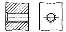
B) in the hole - with solid main lines along the inner diameter of the thread and solid thin lines - along the outer diameter. On cuts parallel to the axis of the hole, a solid thin line along the outer diameter of the thread is drawn for the entire length of the thread without run-off, and on images obtained by projecting onto a plane perpendicular to the axis of the hole, an arc approximately equal to 3/4 of the circle is drawn along the outer diameter of the thread, open in any place (Fig. 3, 4).

A solid thin line when depicting a thread is applied at a distance of at least 0.8 mm from the main line and not more than the thread pitch. 3. The thread, shown as invisible, is depicted by dashed lines of the same thickness along the outer and inner diameters (Fig. 5).

4. The line defining the thread boundary is applied on the rod and in the threaded hole at the end of the full thread profile (before the start of the run). The thread boundary is drawn to the line of the outer diameter of the thread and is depicted as a solid main or dashed line if the thread is shown as invisible (Fig. 6-8).


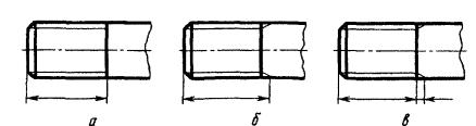
5. Hatching in sections and sections is carried out to the line of the outer diameter of the thread on the rods and to the line inner diameter in the hole, i.e. in both cases to a solid main line (see Fig. 3, 4, 7, 8). 6. The length of the thread with a full profile (without run-off) on the rod and in the hole is indicated as shown in Fig. 9a and hell. 10a. The size of the thread length (with a run) is indicated as shown in Fig. 9b and hell. 10b. If it is necessary to indicate the amount of run-off on the rod, the dimensions are applied, as shown in Fig. 9th century The thread run is depicted as a solid thin straight line, as shown in Fig. 9b, c and hell. 10b.

The undercut of the thread, made to the stop, is depicted as shown in Fig. 11a and c. It is allowed to depict a thread undercut, as shown in Fig. 11b and d.

(Revised edition, Rev. No. 1). 7. The main plane of the tapered thread on the rod, if necessary, is indicated by a thin solid line, as shown in Fig. 12.

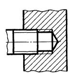
8. In the drawings, according to which the thread is not performed, the end of the deaf threaded hole it is allowed to depict, as shown in Fig. 13 and 14 even if there is a difference between the depth of the threaded hole and the thread length.


9. Chamfers on a threaded rod and in a threaded hole that do not have a special design purpose, in projection onto a plane perpendicular to the axis of the rod or hole, do not depict (Fig. 15-17). A solid thin line of the image of the thread on the rod must intersect the chamfer boundary line (see Fig. 15).

![]()

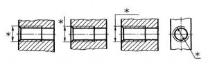
10. A thread with a non-standard profile is shown in one of the ways shown in Fig. 18, with everyone required dimensions and limit deviations. In addition to the dimensions and maximum deviations of the thread, the drawing indicates additional data on the number of entries, on the left direction of the thread, etc. with the addition of the word "Carving".

11. On sections of a threaded connection in the image on a plane parallel to its axis, only the part of the thread that is not closed by the thread of the rod is shown in the hole (Fig. 19, 20).

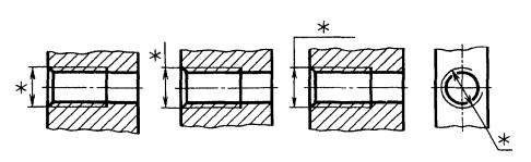
12. The designations of the threads indicate, according to the relevant standards, the dimensions and limit deviations of the threads and refer them for all threads, except for conical and cylindrical pipe threads, to the outer diameter, as shown in Fig. 21, 22.

The designations of conical threads and cylindrical pipe threads are applied as shown in Fig. 23.
GOST 2.311-68
Group T52
INTERSTATE STANDARD
Unified system for design documentation
Unified system for design documentation. image of screw
ISS 01.100.20
Introduction date 1971-01-01
INFORMATION DATA
1. DEVELOPED AND INTRODUCED by the Committee of Standards, Measures and measuring instruments under the Council of Ministers of the USSR
2. APPROVED AND INTRODUCED BY Decree of the Committee of Standards, Measures and Measuring Instruments under the Council of Ministers of the USSR dated May 28, 1968 N 755
3. The standard corresponds to ST SEV 284-76
4. REPLACE GOST 3459-59
5. EDITION (August 2007) with Amendment No. 1 approved in April 1987 (IUS 7-87)
1. This standard establishes the rules for the image and application of the thread designation in the drawings of all industries and construction.
The standard complies with ST SEV 284-76.
2. The carving is depicted:
a) on the rod - with solid main lines along the outer diameter of the thread and solid thin lines - along the inner diameter.
On the images obtained by projecting onto a plane parallel to the axis of the rod, a solid thin line along the inner diameter of the thread is drawn for the entire length of the thread without runaway, and on the views obtained by projecting onto a plane perpendicular to the axis of the rod, along
inner diameter of the thread, an arc is drawn, approx. equal to the circle, open anywhere (Fig. 1, 2);
b) in the hole - with solid main lines along the inner diameter of the thread and solid thin lines - along the outer diameter.
On cuts parallel to the axis of the hole, a solid thin line along the outer diameter of the thread is drawn for the entire length of the thread without runoff, and on images obtained by projecting onto a plane perpendicular to the axis of the hole, an arc is drawn along the outer diameter of the thread,
approximately equal to a circle, open anywhere (Fig. 3, 4).
A solid thin line when depicting a thread is applied at a distance of at least 0.8 mm from the main line and not more than the thread pitch.
3. The thread, shown as invisible, is depicted by dashed lines of the same thickness along the outer and inner diameters (Fig. 5).
4. The line defining the thread boundary is applied on the rod and in the threaded hole at the end of the full thread profile (before the start of the run). The thread boundary is drawn to the line of the outer diameter of the thread and is depicted as a solid main or dashed line if the thread is shown as invisible (Fig. 6-8).

5. Hatching in sections and sections is carried out to the line of the outer diameter of the thread on the rods
and to the line of the inner diameter in the hole, i.e. in both cases to a solid main line
(see fig. 3, 4, 7, 8).
6. The size of the length of the thread with a full profile (without run-off) on the rod and in the hole is indicated, as shown in Fig. 9a and 10a.
The size of the thread length (with a run) is indicated as shown in Fig. 9b and 10b.
If it is necessary to indicate the amount of run-off on the rod, the dimensions are applied, as shown in Fig. 9c.
The thread run is depicted as a solid thin straight line, as shown in Fig. 9b, c and 10b.

The undercut of the thread, made to the stop, is depicted as shown in Fig. 11a and iv.
It is allowed to depict a thread undercut, as shown in Fig. 11b ig.
7. The main plane of the tapered thread on the rod, if necessary, is indicated by a thin solid line, as shown in Fig.12.
8. In the drawings, according to which the thread is not made, the end of a blind threaded hole is allowed to be depicted as shown in Figures 13 and 14, even if there is a difference between the depth of the threaded hole and the length of the thread.
9. Chamfers on a threaded rod and in a threaded hole that do not have a special constructive purpose, in projection onto a plane perpendicular to the axis of the rod or hole, do not depict (Fig. 15-17). A solid thin line of the image of the thread on the rod must cross the line of the chamfer boundary (see drawing 15).

10. A thread with a non-standard profile is shown in one of the ways shown in Fig. 18, with all the necessary dimensions and maximum deviations. In addition to the dimensions and maximum deviations of the thread, the drawing indicates additional data on the number of entries, on the left direction of the thread, etc. with the addition of the word "Carving".
11. On cuts threaded connection in the image on a plane parallel to its axis, only the part of the thread that is not covered by the thread of the rod is shown in the hole (Fig. 19, 20).

12. The designations of the threads indicate, according to the relevant standards, the dimensions and maximum deviations of the threads and refer them for all threads, except for conical and cylindrical pipe threads, to the outer diameter, as shown in Fig. 21, 22.

The designations of conical threads and cylindrical pipe threads are applied as shown in drawing 23.
Note. The "*" sign marks the places where the thread designation is applied.
13. Special threads with a standard profile are abbreviated as Sp and symbol threads.
(Changed edition, Rev. N 1).
The electronic text of the document was prepared by CJSC "Kodeks" and verified by: official publication
Unified system of design documentation: Sat. GOSTs. - M.: Standartinform, 2007
This standard establishes the rules for the image and designation of threads in the drawings of all industries and construction.
| Designation: | GOST 2.311-68* |
| Russian name: | ESKD. Thread image |
| Status: | Current Edition (April 2000) |
| Replaces: | GOST 3459-59 “Drawings in mechanical engineering. Image and designation of the thread " |
| Text update date: | 01.10.2008 |
| Date added to database: | 01.02.2009 |
| Date of entry into force: | 01.01.1971 |
| Designed by: | State Standard of the USSR |
| Approved: | State Standard of the USSR (01.12.1967) |
| Published: | IPK Standards Publishing House No. 2000 |
GOST 2.311-68
INTERSTATE STANDARD
UNIFIED SYSTEM OF DESIGN DOCUMENTATION
THREAD IMAGE
IPK STANDARDS PUBLISHING HOUSE
Moscow
INTERSTATE STANDARD
| Unified system of design documentation IMAGETHREADS Unified system for design documentation. | GOST |
Introduction date 01.01.71
1. This standard establishes the rules for the image and application of the thread designation in the drawings of all industries and construction.
The standard complies with STSEV 284-76.
2. The carving is depicted:
a) on the rod - with solid main lines along the outer diameter of the thread and solid thin lines - along the inner diameter.
On images obtained by projecting onto a plane parallel to the axis of the rod, a solid thin line along the inner diameter of the thread is drawn for the entire length of the thread without run-off, and in views obtained by projecting onto a plane perpendicular to the axis of the rod, an arc is drawn along the inner diameter of the thread, approximately equal to 3/4 of the circle , open anywhere (hell, );
Heck. one
Heck. 2
b) in the hole - with solid main lines along the inner diameter of the thread and solid thin lines - along the outer diameter.
On cuts parallel to the axis of the hole, a solid thin line along the outer diameter of the thread is drawn for the entire length of the thread without run-off, and on images obtained by projecting a plane perpendicular to the axis of the hole, an arc is drawn along the outer diameter of the thread, approximately equal to 3/4 of a circle, open anywhere (heck. ,).
Heck. 3
Heck. 4
A solid thin line in the image of the thread is applied at a distance of at least 0.8 mm from the main line and not more than the thread pitch.
3. The thread, shown as invisible, is depicted by dashed lines of the same thickness along the outer and inner diameters (Fig.).
Heck. 5
4. The line defining the thread boundary is applied on the rod and in the threaded hole at the end of the full thread profile (before the start of the run). The thread boundary is drawn to the line of the outer diameter of the thread and is depicted as a solid main or dashed line if the thread is shown as invisible (Fig. -).
Heck. 6
Heck. 7
Heck. eight
5. Hatching in sections and sections is carried out to the line of the outer diameter of the thread on the rods and to the line of the inner diameter in the hole, i.e. in both cases to a solid main line (see Fig. ,, , ).
6. The size of the length of the thread with a full profile (without run-off) on the rod and in the hole is indicated as shown in the drawing. a and hell. a.
The size of the thread length (with a run) is indicated as shown in Fig. b and hell. b.
If it is necessary to indicate the amount of run-off on the rod, the dimensions are applied, as shown in Fig. in.
The thread run is depicted as a solid thin straight line, as shown in Fig. b, in and hell. b.
Heck. nine
Heck. ten
The undercut of the thread, made to the stop, is depicted as shown in Fig. a and in.
It is allowed to depict a thread undercut, as shown in Fig. b and G.
Heck. eleven
(Revised edition, Rev. No. 1).
7. The main plane of the conical thread on the rod, if necessary, is indicated by a thin solid line, as shown in Fig. .
Heck. 12
8. In the drawings, according to which the thread is not performed, the end of a blind threaded hole is allowed to be depicted as shown in Fig. and , even if there is a difference between the depth of the tap hole and the length of the thread.
Heck. thirteen
Heck. fourteen
9. Chamfers on a threaded rod and in a threaded hole that do not have a special design purpose, in projection onto a plane perpendicular to the axis of the rod or hole, are not depicted (Fig. -). A solid thin line of the image of the thread on the rod must intersect the chamfer boundary line (see Fig.).
Heck. fifteen
![]()
Heck. sixteen
Heck. 17
10. A thread with a non-standard profile is shown in one of the ways shown in Fig. , absolutely necessary sizes and maximum deviations. In addition to the dimensions and limit deviations of the thread, the drawing indicates additional data on the number of entries, on the left direction of the thread, etc. with the addition of the word "Carving".
GOST 2.311-68
INTERSTATE STANDARD
UNIFIED SYSTEM OF DESIGN DOCUMENTATION
THREAD IMAGE
IPK STANDARDS PUBLISHING HOUSE
Moscow
INTERSTATE STANDARD
|
Unified system of design documentation IMAGETHREADS Unified system for design documentation. |
GOST |
Introduction date 01.01.71
1. This standard establishes the rules for the image and application of the thread designation in the drawings of all industries and construction.
The standard complies with ST SEV 284-76.
2. The carving is depicted:
a) on the rod - with solid main lines along the outer diameter of the thread and solid thin lines - along the inner diameter.
On images obtained by projecting onto a plane parallel to the axis of the rod, a solid thin line along the inner diameter of the thread is drawn for the entire length of the thread without run-off, and in views obtained by projecting onto a plane perpendicular to the axis of the rod, an arc is drawn along the inner diameter of the thread, approximately equal to 3/4 of a circle, open anywhere (hell,);
Heck. one
Heck. 2
b) in the hole - with solid main lines along the inner diameter of the thread and solid thin lines - along the outer diameter.
On cuts parallel to the axis of the hole, a solid thin line along the outer diameter of the thread is drawn for the entire length of the thread without run-off, and on images obtained by projecting onto a plane perpendicular to the axis of the hole, an arc approximately equal to 3/4 of the circle is drawn along the outer diameter of the thread, open anywhere (hell, ).
Heck. 3
Heck. 4
A solid thin line when depicting a thread is applied at a distance of at least 0.8 mm from the main line and not more than the thread pitch.
3. The thread, shown as invisible, is depicted by dashed lines of the same thickness along the outer and inner diameters (Fig.).
Heck. 5
4. The line defining the thread boundary is applied on the rod and in the threaded hole at the end of the full thread profile (before the start of the run). The thread boundary is drawn to the line of the outer diameter of the thread and is depicted as a solid main or dashed line if the thread is shown as invisible (Fig. -).
Heck. 6
Heck. 7
Heck. eight
5. Hatching in sections and sections is carried out to the line of the outer diameter of the thread on the rods and to the line of the inner diameter in the hole, i.e. in both cases to a solid main line (see Fig. , , , ).
6. The length of the thread with a full profile (without run-off) on the rod and in the hole is indicated as shown in Fig. a and hell. a.
The size of the thread length (with a run) is indicated as shown in Fig. b and hell. b.
If it is necessary to indicate the amount of run-off on the rod, the dimensions are applied, as shown in Fig. in.
The thread run is depicted as a solid thin straight line, as shown in Fig. b, in and hell. b.
Heck. nine
Heck. ten
The undercut of the thread, made to the stop, is depicted as shown in Fig. a and in.
It is allowed to depict a thread undercut, as shown in Fig. b and G.
Heck. eleven
(Revised edition, Rev. No. 1).
7. The main plane of the tapered thread on the rod, if necessary, is indicated by a thin solid line, as shown in Fig. .
Heck. 12
8. In the drawings, according to which the thread is not performed, the end of a blind threaded hole is allowed to be depicted, as shown in Fig. and , even if there is a difference between the depth of the tap hole and the length of the thread.
Heck. thirteen
Heck. fourteen
9. Chamfers on a threaded rod and in a threaded hole that do not have a special design purpose, in projection onto a plane perpendicular to the axis of the rod or hole, do not depict (Fig. -). A solid thin line of the image of the thread on the rod must intersect the chamfer boundary line (see Fig.).
Heck. fifteen
![]()
Heck. sixteen
Heck. 17
10. A thread with a non-standard profile is shown in one of the ways shown in Fig. , with all the necessary dimensions and limit deviations. In addition to the dimensions and maximum deviations of the thread, the drawing indicates additional data on the number of entries, on the left direction of the thread, etc. with the addition of the word "Carving".
Heck. eighteen
11. On sections of a threaded connection in the image on a plane parallel to its axis, only the part of the thread that is not closed by the thread of the rod is shown in the hole (Fig.
GOST 2.311-68
INTERSTATE STANDARD
UNIFIED SYSTEM OF DESIGN DOCUMENTATION
THREAD IMAGE
The standard complies with ST SEV 284-76.
2. The carving is depicted:
a) on the rod - with solid main lines along the outer diameter of the thread and solid thin lines - along the inner diameter.
On images obtained by projecting onto a plane parallel to the axis of the rod, a solid thin line along the inner diameter of the thread is drawn for the entire length of the thread without run-off, and in views obtained by projecting onto a plane perpendicular to the axis of the rod, an arc is drawn along the inner diameter of the thread, approximately equal to 3/4 circle, open anywhere (Fig. 1, 2);


b) in the hole - with solid main lines along the inner diameter of the thread and solid thin lines - along the outer diameter.
On cuts parallel to the axis of the hole, a solid thin line along the outer diameter of the thread is drawn for the entire length of the thread without run-off, and on images obtained by projecting onto a plane perpendicular to the axis of the hole, an arc approximately equal to 3/4 of the circle is drawn along the outer diameter of the thread, open in any place (Fig. 3, 4).
3. The thread, shown as invisible, is depicted by dashed lines of the same thickness along the outer and inner diameters (Fig. 5).
![]()
4. The line defining the thread boundary is applied on the rod and in the threaded hole at the end of the full thread profile (before the start of the run). The thread boundary is drawn to the line of the outer diameter of the thread and is depicted as a solid main or dashed line if the thread is shown as invisible (Fig. 6-8).
5. Hatching in sections and sections is carried out to the line of the outer diameter of the thread on the rods and to the line of the inner diameter in the hole, i.e. in both cases to a solid main line (see Fig. 3, 4, 7, 8).
6. The length of the thread with a full profile (without run-off) on the rod and in the hole is indicated as shown in Fig. nine a and hell. ten a.
The size of the thread length (with a run) is indicated as shown in Fig. nine b and hell. ten b.
If it is necessary to indicate the amount of run-off on the rod, the dimensions are applied, as shown in Fig. nine in.
The thread run is depicted as a solid thin straight line, as shown in Fig. nine b, in and hell. ten b.
It is allowed to depict a thread undercut, as shown in Fig. eleven b and G.

7. The main plane of the tapered thread on the rod, if necessary, is indicated by a thin solid line, as shown in Fig. 12.
8. In the drawings, according to which the thread is not performed, the end of a blind threaded hole is allowed to be depicted, as shown in Fig. 13 and 14 even if there is a difference between the depth of the threaded hole and the thread length.
9. Chamfers on a threaded rod and in a threaded hole that do not have a special design purpose, in projection onto a plane perpendicular to the axis of the rod or hole, do not depict (Fig. 15-17). A solid thin line of the image of the thread on the rod must intersect the chamfer boundary line (see Fig. 15).
![]()
10. A thread with a non-standard profile is shown in one of the ways shown in Fig. 18, with all the necessary dimensions and limit deviations. In addition to the dimensions and maximum deviations of the thread, the drawing indicates additional data on the number of entries, on the left direction of the thread, etc. with the addition of the word "Carving".

11. On sections of a threaded connection in the image on a plane parallel to its axis, only the part of the thread that is not closed by the thread of the rod is shown in the hole (Fig. 19, 20).
12. The designations of the threads indicate, according to the relevant standards, the dimensions and limit deviations of the threads and refer them for all threads, except for conical and cylindrical pipe threads, to the outer diameter, as shown in Fig. 21, 22.

The designations of conical threads and cylindrical pipe threads are applied as shown in Fig. 23.
![]()
Note. The "*" sign marks the places where the thread designation is applied.
13. A special thread with a standard profile is abbreviated as Sp and a thread symbol.
(Revised edition, Rev. No. 1).
INFORMATION DATA
1. DEVELOPED AND INTRODUCED by the Committee of Standards, Measures and Measuring Instruments under the Council of Ministers of the USSR
2. APPROVED AND PUT INTO EFFECT by the Decree of the Committee of Standards, Measures and Measuring Instruments under the Council of Ministers of the USSR in December 1967
3. The standard complies with ST SEV 284-76
4. REPLACE GOST 3459-59
5. EDITION (August 2007) with Amendment No. 1 approved in April 1987 (IUS 7-87)
We also recommend
 Productive and reproductive thinking
 Reasonable egoism - what is the theory of reasonable egoism?
 Boris Nikolaevich Yeltsin, the first President of Russia
 Underground fights. Underground kings. What is “fighting not for the masses”? Where can you fight for money?
 Yakov Pavlov and Other Heroes of Stalingrad You Need to Know
 Survive an accident at sea in a dream - in reality experience a new love