Water flow through a pipe at pressure calculator. Determination of the throughput capacity of pipelines
B.K. Kovalev, Deputy Director for R&D
Recently, more and more often we have to come across examples when placing orders for industrial gas equipment conducted by managers who do not have sufficient experience and technical knowledge in relation to the subject of procurement. Sometimes the result is not a completely correct application or a fundamentally incorrect selection of ordered equipment. One of the most common mistakes is the choice of nominal sections of the inlet and outlet pipelines of a gas distribution station, oriented only to the nominal values of gas pressure in the pipeline without taking into account the gas flow rate. The purpose of this article is to issue recommendations for determining the throughput of GDS pipelines, which allow, when choosing the standard size of a gas distribution station, to carry out a preliminary assessment of its performance for specific values of operating pressures and nominal diameters of inlet and outlet pipelines.
When choosing the required standard sizes of GDS equipment, one of the main criteria is performance, which largely depends on the capacity of the inlet and outlet pipelines.
Bandwidth pipelines of a gas distribution station is calculated taking into account the requirements normative documents limiting the maximum allowable gas flow rate in the pipeline to 25m/s. In turn, the gas flow rate depends mainly on the pressure of the gas and the cross-sectional area of the pipeline, as well as on the compressibility of the gas and its temperature.
The throughput of the pipeline can be calculated from the classical formula for the velocity of gas in a gas pipeline (Handbook on the design of main gas pipelines, edited by A.K. Dertsakyan, 1977):
where W- speed of gas movement in the gas pipeline, m/s;
Q- gas flow through a given section (at 20 ° C and 760 mm Hg), m 3 / h;
z- compressibility factor (for an ideal gas z = 1);
T = (273 + t °C)- gas temperature, °K;
D- internal diameter of the pipeline, cm;
p\u003d (Prab + 1.033) - absolute gas pressure, kgf / cm 2 (atm);
In the SI system (1 kgf / cm 2 \u003d 0.098 MPa; 1 mm \u003d 0.1 cm), this formula will take the following form:
where D is the inner diameter of the pipeline, mm;
p = (Pwork + 0.1012) - absolute gas pressure, MPa.
It follows that the throughput of the pipeline Qmax, corresponding to top speed gas flow w = 25m/s, determined by the formula:
For preliminary calculations, we can take z = 1; T \u003d 20? C \u003d 293? K and, with a sufficient degree of reliability, carry out calculations using a simplified formula:
![]()
Values of throughput of pipelines with the most common in GDS conditional diameters at various gas pressures are given in Table 1.
| Working (MPa) | Pipeline capacity (m?/h), at wgas=25 m/s; z = 1; T \u003d 20? C \u003d 293? K |
|||||||
|---|---|---|---|---|---|---|---|---|
| DN 50 | DN 80 | DN 100 | DN 150 | DN 200 | DN 300 | DN 400 | DN 500 | |
Note: for a preliminary assessment of the throughput of pipelines, inner diameters pipes are taken equal to their conventional values (DN 50; 80; 100; 150; 200; 300; 400; 500).
Examples of using the table:
1. Determine the capacity of the GDS with DNin=100mm, DNout=150mm, with PNin=2.5 - 5.5 MPa and PNout=1.2 MPa.
From table 1 we find that the capacity of the outlet pipeline DN=150mm at PN=1.2 MPa will be 19595 m 3 / h, at the same time the inlet pipeline DN=100 mm at PN=5.5 MPa will be able to pass 37520 m 3 / h , and at PN=2.5 MPa - only 17420 m 3 /h. Thus, this GDS with PNin=2.5 - 5.5 MPa and PNout=1.2 MPa will be able to pass from 17420 to 19595 m 3 /h as much as possible. Note: more exact values Qmax can be obtained from formula (3).
2. Determine the diameter of the outlet pipeline of the GDS, with a capacity of 5000 m 3 / h at Pin=3.5 MPa for outlet pressures Pout1=1.2 MPa and Pout2=0.3 MPa.
From table 1 we find that a throughput of 5000m 3 /hour at Pout=1.2 MPa will be provided by a pipeline DN=80mm, and at Pout=0.3 MPa - only DN=150mm. At the same time, it is enough to have a pipeline DN=50mm at the GDS inlet.
This characteristic depends on several factors. First of all, this is the diameter of the pipe, as well as the type of liquid, and other indicators.
For hydraulic calculation of the pipeline, you can use the pipeline hydraulic calculation calculator.
When calculating any systems based on the circulation of fluid through pipes, it becomes necessary to accurately determine pipe capacity. This is a metric value that characterizes the amount of fluid flowing through pipes in a certain period of time. This indicator is directly related to the material from which the pipes are made.
If we take, for example, plastic pipes, then they differ in almost the same throughput throughout the entire period of operation. Plastic, unlike metal, is not prone to corrosion, so a gradual increase in deposits is not observed in it.
As for metal pipes, their throughput decreases year after year. Due to the appearance of rust, material detachment occurs inside the pipes. This leads to surface roughness and the formation of even more deposits. This process occurs especially quickly in pipes with hot water.
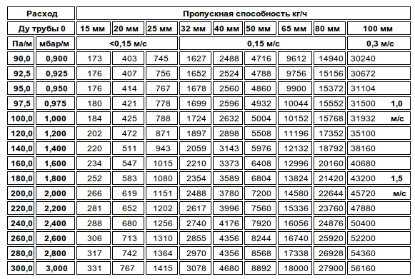
The following is a table of approximate values \u200b\u200bwhich was created to facilitate the determination of the throughput of pipes for intra-apartment wiring. This table does not take into account the reduction in throughput due to the appearance of sediment buildup inside the pipe.
Pipe capacity table for liquids, gas, steam.
|
Liquid type |
Speed (m/s) |
|
City water supply |
|
|
Water pipeline |
|
|
Water system central heating |
|
|
Water pressure system in the pipeline line |
|
|
up to 12m/s |
|
|
Oil pipeline line |
|
|
Oil in the pressure system of the pipeline line |
|
|
Steam in the heating system |
|
|
Steam central pipeline system |
|
|
Steam in a high temperature heating system |
|
|
Air and gas in the central piping system |
Most often, ordinary water is used as a coolant. The rate of decrease in throughput in pipes depends on its quality. The higher the quality of the coolant, the longer the pipeline made of any material (steel, cast iron, copper or plastic) will last.
Calculation of pipe throughput.
For accurate and professional calculations, you must use the following indicators:
- The material from which pipes and other elements of the system are made;
- Pipeline length
- Number of water consumption points (for water supply system)
The most popular calculation methods:
1. Formula. Enough complex formula, which is understandable only to professionals, takes into account several values at once. The main parameters that are taken into account are the material of the pipes (surface roughness) and their slope.
2. Table. This is an easier way by which anyone can determine the throughput of the pipeline. An example is the engineering table of F. Shevelev, by which you can find out the throughput based on the pipe material.
3. Computer program. One of these programs can be easily found and downloaded on the Internet. It is designed specifically to determine the throughput for pipes of any circuit. In order to find out the value, it is necessary to enter the initial data into the program, such as material, pipe length, coolant quality, etc.
It should be said that the latter method, although it is the most accurate, is not suitable for calculating simple household systems. It is quite complex and requires knowledge of the values of a variety of indicators. To calculate a simple system in a private house, it is better to use tables.
An example of calculating the throughput of the pipeline.
The length of the pipeline is an important indicator in calculating the throughput. The length of the main line has a significant impact on the throughput performance. The more distance the water travels, the less pressure it creates in the pipes, which means that the flow rate decreases.
Here are some examples. Based on tables developed by engineers for these purposes.
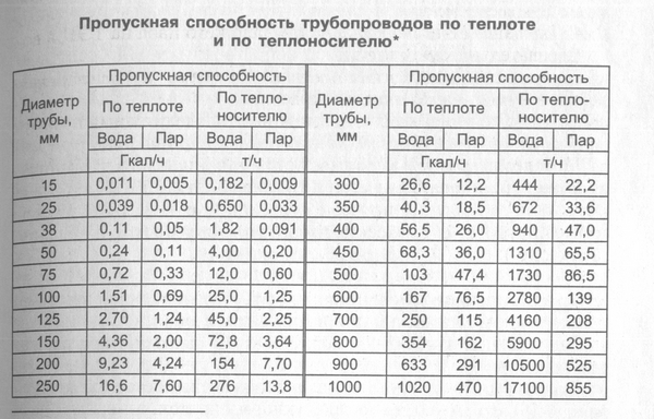
Pipe capacity:
- 0.182 t/h at 15 mm diameter
- 0.65 t/h with pipe diameter 25 mm
- 4 t/h at 50 mm diameter
As can be seen from the examples above, a larger diameter increases the flow rate. If the diameter is increased by 2 times, then the throughput will also increase. This dependence must be taken into account when installing any liquid system, whether it be water supply, sewerage or heat supply. Especially it concerns heating systems, since in most cases they are closed, and the heat supply in the building depends on the uniform circulation of the liquid.
In every modern home one of the main conditions of comfort is running water. And with the advent of new technology that requires connection to the water supply, its role in the house has become very important. Many people no longer understand how to do without washing machine, boiler, dishwasher etc. But each of these devices correct operation requires a certain pressure of water coming from the water supply. And now a person who decides to install a new water supply in his house thinks about how to calculate the pressure in the pipe so that all plumbing fixtures work well.
The requirements of modern plumbing
Modern plumbing must meet all the requirements and characteristics. At the outlet of the tap, water should flow smoothly, without jerking. Therefore, there should be no pressure drops in the system when parsing water. The water flowing through the pipes should not create noise, have air impurities and other extraneous accumulations that adversely affect ceramic taps and other plumbing. To avoid these unpleasant incidents, the water pressure in the pipe should not fall below its minimum when parsing water.
Note! The minimum water supply pressure should be 1.5 atmospheres. This pressure is enough to operate the dishwasher and washing machine.
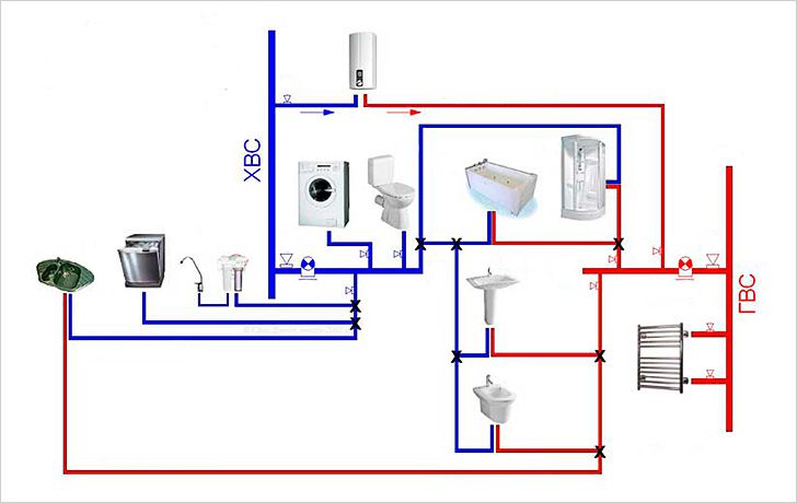
It is necessary to take into account another important characteristic of the water supply system related to the flow of water. In any residential area there is more than one point of water analysis. Therefore, the calculation of the water supply system must fully meet the water demand of all plumbing fixtures while being turned on. This parameter is achieved not only by pressure, but also by the volume of incoming water that a pipe of a certain section can pass. talking plain language, before installation, it is required to perform a certain hydraulic calculation of the water supply, taking into account the flow and pressure of water.
Before the calculation, let's take a closer look at two such concepts as pressure and flow in order to understand their essence.
Pressure
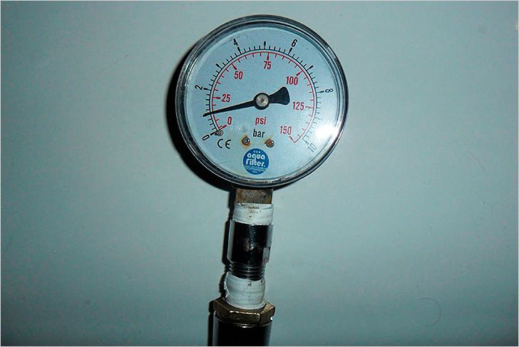
As you know, the central water supply in the past was connected to a water tower. It is this tower that creates pressure in the water supply network. The unit of pressure is the atmosphere. Moreover, the pressure does not depend on the size of the tank located at the top of the tower, but only on the height.
Note! If you pour water into a pipe ten meters high, then it will create pressure at the lowest point - 1 atmosphere.
Pressure is equal to meters. One atmosphere equals 10 meters of water. Consider an example with five-story building. The height of the house is 15 m. Therefore, the height of one floor is 3 meters. A fifteen-meter tower will create a pressure of 1.5 atmospheres on the ground floor. Let's calculate the pressure on the second floor: 15-3=12 meters of water column or 1.2 atmospheres. Having made a further calculation, we will see that there will be no water pressure on the 5th floor. This means that in order to provide water to the fifth floor, it is necessary to build a tower of more than 15 meters. And if it is, for example - 25 storey building? No one will build such towers. Pumps are used in modern plumbing.
Let's calculate the pressure at the outlet of the deep pump. Available submersible pump, raising water by 30 meters of water column. This means that it creates pressure - 3 atmospheres at its outlet. After immersing the pump into the well by 10 meters, it will create pressure at ground level - 2 atmospheres, or 20 meters of water column.
Consumption
Consider the next factor - water consumption. It directly depends on the pressure, and the higher it is, the faster the water will move through the pipes. That is, there will be more expenses. But the thing is that the cross section of the pipe through which it moves affects the speed of water. And if you reduce the cross section of the pipe, then the water resistance will increase. Consequently, its amount at the outlet of the pipe will decrease over the same period of time.
In production, during the construction of water pipelines, projects are drawn up in which the hydraulic calculation of the water supply system is calculated according to the Bernoulli equation:
Where h 1-2 - shows the pressure loss at the outlet, after overcoming the resistance in the entire section of the water supply.
We calculate home plumbing

But it is, as they say, complex calculations. For home plumbing, we use simpler calculations.
Based on the passport data of the machines consumed by the water in the house, we summarize the total consumption. We add to this figure the consumption of all water taps located in the house. One faucet passes through itself about 5-6 liters of water per minute. We sum up all the numbers and get the total water consumption in the house. Now, guided by the total consumption, we buy a pipe with a cross section that will provide the right amount and water pressure of all simultaneously operating water folding devices.
When the home water supply is connected to the city network, you will use what they will give you. Well, if you have a well at home, buy a pump that will fully provide your network with the necessary pressure corresponding to the costs. When buying, be guided by the passport data of the pump.
To select a pipe section, we are guided by these tables:
| The dependence of the diameter on the length of the water supply | pipe capacity | |||
| pipeline length, m |
pipe diameter, mm |
pipe diameter, mm |
throughput, l/min |
|
| Less than 10 | 20 | 25 | 30 | |
| 10 to 30 | 25 | 32 | 50 | |
| Over 30 | 32 | 38 | 75 | |
These tables provide more popular pipe parameters. For a complete acquaintance on the Internet, you can find more complete tables with calculations for pipes of different diameters.
Here, based on these calculations, and with proper installation, you will provide your plumbing with all the required parameters. If something is not clear, it is better to contact the experts.
We also recommend
 Switching power supply: repair and refinement
 Remote control of light
 Swimming lessons for preschool children
 Notes for the master - home household alarms
 Clock propeller on Atmega8
 Device and relay application examples, how to choose and connect a relay correctly Microcontroller and relay simple switching circuits