Photo relay circuits for lighting control. Light sensor (photo relay) for street lighting Do-it-yourself photo relay with transistors
The creation of a sensor responsive to light was described and examples of control circuits for a low-power electric motor and LED were given. It would be more useful to control some powerful load, for example: an incandescent lamp, a powerful electric motor, etc. A simple photo relay circuit for a powerful load is shown in Figure 1:
Figure 1 - Photo relay triggered when illumination decreases
without sensitivity adjustment
This circuit uses an electromagnetic contact relay. The simplest, cheapest and most accessible way to control a powerful load is to use an electromagnetic contact relay:

The relay shown in the photo above was removed from a broken imported refrigerator; this relay can switch (connect and disconnect in this case) a load consuming a current of no more than 16A. 16A is quite enough for many household electrical appliances. On the body of this relay it is written that 12 V is required for the DC coil, but in practice, 9 V from the power supply for the modem with a rectifier was enough to operate this relay:

If 9V is not enough, you can power the circuit from 12V. If you replace resistor R1 with a variable or trimmer, you can adjust the sensitivity to light.


The reverse current of this photodiode is amplified by transistor VT1:

This transistor forms a voltage divider together with resistor R1:

As mentioned above, this resistor can be replaced with a variable or trimmer so that the sensitivity of the circuit can be adjusted.
Transistor VT2 directly controls the relay coil:
KT973 is well suited for this purpose. The relay is connected to the collector of this transistor.
To prevent transistor VT2 from burning out when it is suddenly closed, a reverse diode is placed parallel to the relay coil:

This diode can be replaced with any other suitable diode.
Resistor R2 is not required, but it can be installed to limit the current or reduce its consumption.

The power part of the circuit requires connectors and wires:

The relay can connect the load to a 220V network. Do not forget that the mains voltage is dangerous and when working with it you must take precautions to avoid electric shock.
After preparing all the necessary parts, you can begin assembling the relay.


It is better to solder the reverse diode directly to the relay.


A load with a power source (not necessarily a 220V network) can be connected to the assembled relay. Using this photo relay paired with an infrared radiation source, you can make a presence sensor:


Figure 2 - Scheme turning on the load with increasing lighting
If a photo relay turns on an incandescent lamp when the illumination decreases, then it is necessary to somehow close the photodiode from the light of the incandescent lamp, otherwise, when the illumination decreases, the relay will begin to turn on and off frequently, which will lead to its rapid wear and failure. If an infrared photodiode is used, then the photo relay will not respond to the light of a fluorescent lamp (if it is not brought close enough) or an LED lamp (if it does not have infrared LEDs with the corresponding wavelength of emitted light). It is better not to test the IR control panel on this photo relay:
Capacitive photo relay for street lighting is a device that allows you to turn on or off lamps used on roads, at entrances and in parks. Their use saves energy and minimizes inconvenience for drivers, home residents and ordinary passers-by.
The work is based on a photoresistor or photodiode - semiconductor elements that change their parameters depending on the intensity of lighting in the environment. During the day, when there is sufficient light, the light sensor opens the circuit and the lamp turns off, and at night the reverse sequence of actions occurs: the capacitive relay for controlling the lighting reduces the resistance and the light turns on.
Installation of photo relay
It is not difficult to install a photo relay with your own hands; it is only important to exclude the direct influence of the adjustable light source and protect the device from adverse external influences: moisture, direct sunlight, temperature changes.
For industrial devices, there are a number of standards that such solutions must comply with: GOST (domestic) and IP (international). It is more difficult to ensure that a homemade photo relay is protected from environmental factors, although it is theoretically possible. But for those who want to install such a device in their yard, near their entrance or garage, it is better to first consider the solutions offered on the market - without having the necessary knowledge and experience, it will be extremely difficult to bring the photo sensor to working condition with your own hands.
FR-601 (602)
When it comes to using standard single-phase photo relays for lighting, the most popular model is the FR-601 and FR-602 devices manufactured by IEK.
They are quite reliable, and even users uninitiated in electronics have no questions about how to connect an automatic backlight controller. These two modifications have minor differences: they both operate with current of the same voltage and frequency, have similar power consumption (0.5 W) and absolutely identical delivery kits.
The differences relate only to the maximum cross-section of the connected conductors: for the 601 model it is 1.5 square meters. mm., and for 602 - 2.5. Consequently, their rated load current is also different: 10 and 20 A, respectively. Both models have a built-in photocell; it can be adjusted from 0 to 50 lux in increments of 5 lux.

Making at home
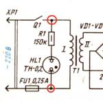
The schematic diagram of the FR-602 capacitive photorelay (like its brother) is easily repeated even with little knowledge of electronics. Creating a homemade product becomes especially relevant when there is a need for a large number of devices (for example, to organize automatic switching on and off of lighting depending on the time of day).

For manufacturing you will need the following parts; the designation on the diagram and power will be indicated in brackets:
- 2 bipolar transistors BC857A (Q1 and Q2);
- 5 rectifier diodes 1N4007;
- rectifier diode 1N4148;
- Zener diode 1N4749;
- resistors (R2, R4–R9: 1.5 MΩ, 1 MΩ, 560 kΩ, 200 kΩ, 100 kΩ, 75 kΩ and 33 kΩ; all 0.125 W);
- resistor (R3, 220 Ohm, 2 W);
- photocell (PH, up to 100 kOhm);
- trimming resistor (WL, 2.2 mOhm);
- capacitor (C2, 0.7 µF 400 V);
- electrolytic capacitors (C4–C5, 100 μF 50 V and 47 μF 25 V, respectively);
- relay SHA-24VDC-S-A (Rel1).

Considering the set and total cost of parts, as well as the availability of a diagram, model 602 is a fairly simple solution to implement.

By the way, many parts from the list can be replaced with domestic ones. According to reviews from those who have already assembled, the Q2 bipolar transistor can be replaced by the ubiquitous KT3107B, and the 1N4749 zener diode can be replaced by three D814A or two D814D connected in series. The connection diagram is also not particularly complicated.

Disadvantages of the model
Let's look at the disadvantages of such a scheme. Oddly enough, from a technical point of view, the circuit is not inferior to the factory one with the proper skill of a radio amateur. The difference will be felt in actual use: the factory product has an IP44 protection standard, which means dust and moisture protection.
Also, factory FR-601 and FR-602 have a larger operating temperature range, and a homemade circuit in the cold in December may stop working due to a single poor-quality connection.
Analogs
Among the analogues of this device are the FR-75A - a photo relay, the circuit of which is more complex for manufacturing at home, and is also less stable and durable in practical use.

Among its advantages is a larger range of operating brightness, ranging from 1 to 200 lux, which is four times higher than the competitor. Another big advantage of the FR-75 device is the ability to operate in 12 V DC circuits.
Also, the photosensor is remote, which allows you to install the regulator itself indoors and not worry about environmental factors. In general, the model has no equal in its class and is the best photo relay - 12 volts DC is often used as power for such devices. The device connection diagram is shown in the figure.

High power equipment
Among the competitors, you can also consider the FR-7E photo relay, but the lack of moisture protection (IP40) and rather high power consumption are not in its favor.

Disadvantages also include open contact clamps and lack of protection for the trimming resistor on the front panel. A positive point is that the FR-7 can operate in AC networks of 220 volts with a voltage of up to 5 amperes, which is almost an order of magnitude greater than that of the competitors discussed above. The adjustment range of 10 lux is also set only by a specialist - you cannot adjust it yourself.

In terms of dimensions, the FR-7 also exceeds the photo relays discussed in the article (see drawing).

Conclusion
Taking into account the experience of operating photo relays in domestic and industrial conditions, the most stable and easily reproducible at home is the FR-602 model or its less powerful variation FR-601 from AIK. They perform well in various operating modes, have a good durability margin and, most importantly, have a minimum cost. In addition, their assembly is facilitated by the ability to replace many foreign parts with cheap domestic analogues.
Video
Technological progress is making people's lives more and more comfortable. For this purpose, new devices are being invented that perform actions without the presence and participation of people.
One such device is a simple photo relay. You can buy such a device in a store, but it’s more interesting and economical to make it yourself.
A photo relay can be used to turn lights on or off at different times of the day. For example, when darkness sets in, the device turns on the lighting, and at dawn it turns off. It can also be used at the entrance of an apartment building or on your own country site.
It is widely used with a photo relay, which turns the lighting on and off in autonomous mode. Such a device can be used in a “smart home”. At the same time, using a photo relay you can not only control the lighting, but also open the blinds or ventilate the room. It should be noted that this device can be installed for a home security system.
Let's understand the circuit of a simple photo relay with our own hands
The simplest photo relay circuit consists of two transistors, a photoresistor, a relay, a diode and a variable resistor. Devices of the KT315B type are used, connected according to the circuit of a composite transistor, the load of which is the relay winding. This circuit has a high gain and high input resistance, which allows it to include a photoresistor with high resistance. 
With increasing illumination of the photoresistor connected between the collector and the base of the first transistor, this transistor and transistor No. 2 open. As a result of the appearance of current in the collector circuit of the second transistor, the relay will operate, which, with its contacts, depending on its settings, will turn on or off the load.
To protect the circuit from the effects of self-induction EMF when the relay is turned off, a protective diode of type KD522 is included. To adjust the sensitivity of the circuit, a variable transistor with a nominal value of 10 kOhm is connected between the base and emitter of the first transistor.
In addition to installation in residential and utility rooms, walk-through platforms are used. The connection diagram depends on the number of pins to the light system.
The machines are installed in the electrical panel to protect the electrical network from overload and short circuit - this is what it consists of.
Such a photo relay can be powered from a DC voltage source of 5 - 15 V. In this case, with a source voltage of 6 volts, relays of the RES 9 or RES 47 type are used, and with a supply voltage of 12 V, relays RES 15 or RES 49 are used.
To mount the circuit, you can create a special board, if possible a printed circuit board. Then attach relays, transistors, a variable resistor to the board, make holes for the terminals of the circuit elements and make the appropriate connections using mounting wires and.
The circuit can be set up in a shaded room using an incandescent lamp, from which the light flow can be adjusted.
At the required illumination, the circuit's response threshold is selected using a variable resistor. If in the future it is not planned to adjust the response threshold, then instead of a variable one, a constant one is set, the resistance of which corresponds to the value obtained during the adjustment.
Assembly method on a modern device
 When using more complex electronic devices, you can assemble a homemade photo relay, which includes only three components. Such a circuit can be assembled on an integrated semiconductor device from TeccorElectronics Q6004LT (quad), which has a built-in dinistor. Such a device has an operating current of 4 A and an operating voltage of 600 V.
The photo relay connection diagram consists of a Q6004LT device, a photoresistor and a conventional resistor. The circuit is powered from a 220 V network. In the presence of light, the photoresistor has a low resistance (several kOhms), and a very low voltage is present at the control electrode of the quad. The quad is closed and no current flows through its load, which can be lighting lamps.
As the illumination decreases, the resistance of the photoresistor will increase, and the voltage pulses arriving at the control electrode will also increase. When the voltage amplitude increases to 40 V, the triac will open, current will flow through the load circuit and the lighting will turn on.
A resistor is used to configure the circuit. The initial value of its resistance is 47 kOhm. The resistance value is selected depending on the required illumination threshold and the type of photoresistor used. The type of photoresistor is not critical. For example, elements of the type SF3-1, FSK-7 or FSK-G1 can be used as a photoresistor.
 You don't have to be a master to know... You just need to learn how to correctly identify breakdowns and remember a few simple rules for correcting them.
A modern power supply system provides three-wire wiring from or to an apartment. Taking into account such conditions, and are established.
Using the powerful Q6004LT device allows you to connect a load of up to 500 W to the photo relay, and when using an additional radiator, this power can be increased to 750 W. To further increase the load power of the photo relay, you can use a quad with operating currents of 6, 8, 10 or 15 A.
Thus, the advantage of this scheme, in addition to the small number of parts used, is the absence of the need for a separate power supply and the ability to switch powerful consumers of electrical energy.
Installation of this circuit is not particularly difficult due to the small number of circuit elements. Setting up the circuit consists of determining the desired threshold for the circuit to operate and is carried out in a manner similar to the previous circuit.
conclusions:
- In various automatic control systems, most often in lighting systems, photo relays are used.
- There are many different photo relay circuits using photoresistors, photodiodes and phototransistors as sensors.
- The simplest photo relay circuits, which contain a minimum of parts, can be assembled with your own hands.
Video with an example of assembling a homemade photo relay
With the onset of evening, the lights along the city streets light up on their own; the automation of this process no longer surprises anyone. Today, photo sensors that control street lighting are available not only to public utilities, but also to ordinary owners of country houses. You can make your home more comfortable and smart without any special financial costs or electrical installation skills; you just need to take into account several important nuances: know the photo relay connection diagram and the rules for working with it.
How does the light sensor work?
The task of the photo relay is to turn on the lighting device when it becomes twilight in the yard and turn it off at dawn. The device is based on a photosensitive element (photodiode, gas discharger, photothyristor, photoresistor), which changes its characteristics in light. For example, in a photoresistor the resistance decreases, current easily passes through this element and closes a contact that turns off the lighting.
 Several lighting devices can be connected to one sensor
Additional elements of the device help to avoid erroneous switching on/off, adjust the sensitivity of the sensor, strengthen the signal from the sensor, etc.
Why do you need a photo relay?
 Light accents around the house are not only convenient, but also beautiful
The street lighting system can operate without photosensors. But the day-night sensor gives it additional advantages:
- Convenience. A standard lighting system involves installing a switch near the front door on the street, or in the house itself. This is convenient for those who decide to leave the house late in the evening. But when returning home in the dark, you have to go to the switch with a flashlight, or even open the lock in complete darkness. With the sensor, you can set the backlight to turn on at dusk and the owner will arrive at an already illuminated area at the gate or in front of the garage.
- Energy Saving. Residents of country houses often forget to turn off the lights outside before going to bed or leaving home. This will not happen with a sensor. The standard one will turn off the light with the first rays of the sun, combined with a motion sensor - as soon as everyone leaves the yard, and the programmable one - at exactly the specified time.
- Presence simulation. Thieves do not risk sneaking into a house while the owners are home, and the main sign of their presence is the light being on. Street lighting with a sensor creates the appearance of presence and thus protects the house from vandals and robbers while the family is on vacation or on a business trip.
Light sensors have proven themselves well in urban lighting systems; they are often used by public utilities, owners of shopping centers, parking lots, billboards, etc. In private country houses, photo relays are also beneficial and appropriate, and therefore are becoming increasingly popular.
Selecting a photosensor model taking into account technical characteristics
 Technical characteristics are often indicated directly on the photo relay body
When purchasing, pay attention to:
- Voltage (volts). Manufacturers produce devices powered by mains voltages of 12V, 24V and 220V. We recommend choosing the latter, as they can be connected to a household network. For other devices, you will have to purchase voltage converters, which will make the designs more expensive and less reliable.
- Switching current (amps). If this setting is not selected correctly, the life of the sensor will be significantly reduced. Therefore, the number of lighting devices connected to the photo relay and the type of lamps used (diode, housekeeper, incandescent) need to be determined before choosing a sensor. To obtain the maximum switching current, you need to divide the sum of the powers of all lamps by 220 (mains voltage). The figure indicated in the device passport must be greater than that obtained as a result of calculations.
- Switching threshold (lumens). The parameter determines the sensitivity of the sensor to light. If the sensor is insensitive, the lighting will start to turn on too early, and if the sensor is too sensitive, it will prevent it from turning on in winter due to the reflection of light from the snow. Look in the passport at the threshold adjustment parameters; the range should be 2–100 Lux or 5–100 Lux.
- On/off delay (seconds). The adjustment range is also indicated in the device passport. It should be possible to set a delay of 5-7 seconds so that the lights don't turn off every time a car drives by.
- Power (watts). The lower this indicator, the more economical the device will be. The device passport indicates power consumption in the active phase (up to 5 W) and in standby mode (up to 1 W).
- Degree of protection. Since street lighting sensors are mounted outdoors, drops and moisture vapor should not penetrate into the housing, it should not be deformed due to ultraviolet radiation, etc. The weather resistance of the device must be IP44. If the sensor is placed in a protective box or under a canopy, the figure may decrease. If you select a model with an external photo relay, the degree of protection can be reduced only for the photo sensor, but not for the main unit.
If your region has very harsh winters, pay attention to the operating temperature range, and if there is little space on the facade, give preference to compact models.
Types of light sensors
Conventional inexpensive light sensors allow you to automate lighting and adjust it to the length of daylight hours. But since in this case the light burns all night, manufacturers began to create models with greater capabilities.
 Example of a photo relay with a motion sensor
Among them:
- . They turn on the lights when something starts to move in the controlled area. Thanks to the photo sensor, the switch-on signal is triggered only during the dark period. The device is inexpensive, reliable and compact. But if there are pets running around the area, or there are plant branches in the field of view of the sensor, there is a high probability of a false sensor response.
- Photo relay equipped with both a motion sensor and a timer. The device can be finely tuned so that it only works when needed. For example, from 20.00 to 22.00 when a guest approaches the gate or the owner returns.
- Photo relay with timer. The device makes it possible to save energy by turning off the lights when not in use. If the family’s habits are established and tied to a certain time, this option can be very convenient. Many people prefer this type of device, since they do not have to be installed outside; the timer can give a signal to turn on directly from the house.
- Programmable photo relays. Devices of this type are the most expensive, but superior to other types in functionality. They make it possible to set the lighting on/off depending on natural illumination, time period, day of the week, and season.
The optimal price and functionality are day-night devices with a motion sensor and built-in timers. For the vast majority of everyday tasks, the scenarios they implement are quite sufficient.
Another approach to classifying photosensors is the type of design. There are:

If you have little experience in installing electrical appliances, or you are afraid of damaging the new wallpaper, it is better to prefer an externally mounted photo relay.
Photo relay manufacturers: countries and prices
The production of such devices does not require unique equipment or complex technological processes, therefore, along with Western products, the market offers many domestic photo sensors. Moreover, each country has both budget and inexpensive models with varying degrees of protection.
Comparison table of photo relays from different manufacturers
| Name | Switching current, A | Operating voltage in the network, V | Degree of protection, IP | Manufacturer | price, rub. |
|---|---|---|---|---|---|
| FR-6 | 10 | 240 | 54 | Ukraine | 150 |
| PS-1 | 6 | 220 | 44 | Uzbekistan | 200 |
| HOROZ HL 472 | 25 | 230 | 44 | Türkiye | 210 |
| FERON SEN 27 | 25 | 220 | 54 | China | 250 |
| FR-601 | 5 | 230 | 44 | Russia | 420 |
| SOU-1 | 16 | 230 | 56 | Czech | 650 |
| Lux-2 | 8 | 230 | 44 | Russia | 800 |
| Luna 126 Star Theben | 16 | 230 | 55 | Germany | 2500 |
If you find a model with a suitable switching current, degree of protection and other parameters among products from Russian manufacturers, you should not overpay for the German analogue. But you shouldn’t save too much, as this will affect the durability of the sensor.
Photo relay IEK
Photo relays from the Russian manufacturer IEK are very popular in our country.
 The IEK FR 601 and FR 602 photo relays look the same, pay attention to the markings
Table of characteristics of IEK photo sensors
| Options | FR-600 | FR-601 | FR-602 |
|---|---|---|---|
| Maximum load when used with incandescent lamps, W | 1300 | 1100 | 2500 |
| Maximum load when used with fluorescent lamps, W | 780 | 600 | 1500 |
| On-state power, W | 0,45–6,6 | 0,45–6,6 | 0,45–6,6 |
| Maximum load current, A | 3–6 | 10 | 20 |
| Operating illumination level, Lux | 5–15 (without adjustment) | 5–50 | 5–50 |
| Deferment period, s | - | 16 | 16 |
| Protection level according to GOST 14254 | IP44 | IP44 | IP44 |
| Degree of protection against electric shock | - | II | II |
| Operating temperature range, o C | -25 … +40 | -25 … +40 | -25 … +40 |
All models of sensors of this brand are made of non-flammable plastic (polycarbonate), which protects the house from accidental fire. According to their technical characteristics, the devices are suitable for Europe and central Russia, with the exception of very hot regions and the Far North.
Choosing a location for installation
 The photosensor is located outside the flashlight illumination area
If the sensor is placed incorrectly, the entire system will not function properly. Therefore, the location of the photosensor should be located:
- away from high fences, trees, awnings and other obstacles to natural light;
- in an area illuminated only by sunlight and not by lanterns;
- far from combustible and flammable materials (in case of a short circuit);
- in areas that are not exposed to chemical influences and mechanical shocks.
It is also advisable that the sensor is not too high, then it can be wiped from dust from time to time without using a ladder.
Schemes for connecting a photo relay to a lantern
To install the day-night sensor, no specialized knowledge is required, and tips are printed either on the packaging or on the device itself. Depending on the model, two or three wires come out of the photosensor housing.
 Connection diagram for photo relay with grounding
Three wires come out of the universal device:
- phase (red, marked L);
- zero (blue, marked N);
- grounding (green, PE marking).
 Stand for demonstrating the correct connection of a photo relay
The photo example shows that two cables should enter the device, each of them with three colored wires. Cable 1 is designed to connect to the light bulb. Its blue terminal is connected to the N terminal, and the red one to the L terminal, in the same way they are connected to the light bulb socket. The ground wire is connected to the green wire of cable 2 and secured with a screw. Cable 2 is required to power the device; its red and blue wires are connected in the same way, to the adjacent terminals N and L.
 Connection diagram for photo relay without ground wire
There are models with two terminals, there is no ground wire. Such photo sensors are suitable for houses where the grounding system is equipped separately.
Their connection method is even simpler: the incoming cable is connected to terminals L and N (phase and zero, respectively), and only the phase cable is connected for the output. Zero is supplied to the lamp through the KM starter, past the photosensor.
If the photosensor must control several light bulbs, you need to add a controller to it.
 Connection diagram for a photo sensor for three bulbs
The controller connects to the output terminals of the photosensor and adds another contact pair. With its help, lamps can be connected in parallel rather than in series (as in a Christmas tree garland). Connecting several consumers through the controller makes the circuit more reliable and allows the lamps to light even when one of them fails.
Video instructions for connecting and setting up a photo relay
DIY making
Having minimal skills in using a soldering iron, you can assemble a simple relay yourself. To begin with, you should use a circuit with a minimum of components.
 Even a beginner can assemble such a photo relay
You will need:
- PR1 - photoresistor;
- R1 - 10K electrolytic capacitor;
- VD1 KD522 - protective thermoelectric diode;
- VT1 and VT2 - n-p-n structure transistors;
- KT315B - transistor;
- K1 - 10,000 microfarad electrolytic capacitor;
- K1.1 - on/off switch;
- neutral and phase wires.
These parts can be bought at a radio store, or soldered from old unnecessary equipment.
In this circuit, transistors VT1 and VT2 form an emitter follower, thanks to which the signal from the photosensor is amplified and is powerful enough to open the electrical circuit. Thanks to the diode VD1, reverse current flow is prevented. And the relay completely replaces the transistor cascade used in more complex circuits.
 Self-assembled photo relay
To assemble the photosensor, you need to solder the legs of the elements used in series, or use a board with contacts. To make sure the product is working, it is advisable to test it on a stand with one lamp. In order to set the appropriate sensitivity of the device, it is necessary to solder a variable resistor into the circuit. Change the resistance of the resistor until the device begins to give an on/off signal at the correct level of illumination (experiments can be carried out in the evening with the lamps turned off). As soon as the desired resistance level is found, instead of an adjustable resistor, you need to solder a constant one. As a housing for the product, you can use a distribution box for external installation of electrical wiring, only you need to make a window in it for the photoresistor.
Since the relay allows the circuit to be used on a 220V network, it can be connected in the same way as a purchased one.
Video instructions for making a photosensor for LED lighting
Settings
If you bought a photo sensor ready-made, you will need to adjust its parameters so that the light does not turn on too early and does not burn when it is already light outside.
 Photo relay sensitivity setting
Looking under the photosensor cover, it is easy to notice a round knob, by turning which the light sensitivity of the device is set. To begin, set it to the extreme right position (indicated by a minus sign). This means that it will take pitch darkness to turn on the lights. Connect the sensor to the network and at the time when you would like to turn on the street lighting, open the case and turn the lever until the sensor gives a signal to turn on. Leave the lever in the same position and the system will always start at the same light level.
Since the light reflected from the snow can lead to the light turning off too quickly in the winter, the light sensitivity of the sensor should be reduced and increased again in the spring according to the described scheme.
 Adjusting photo relay with remote sensor
In more complex photo relays with remote sensors, the on/off delay time is also adjusted. To change, you also need to switch the corresponding lever, only it does not turn smoothly, but from one position to another. The positions and levers are marked directly on the body, so there will be no problems with setup.
Possible malfunctions of the street lighting mechanism
If the photo sensor does not work correctly, the reason most often lies in installation or configuration errors.
First, make sure that there is no street light or high fence in front of the day-night device, maybe the tree has become much taller since installation, or has begun to shade the area more when leaves appear on it. Such obstacles must be removed or the photo relay moved to a more suitable location.
It is also possible that one of the residents of the house accidentally changed the settings, or they became irrelevant with the change of season. Monitor the set light sensitivity and set the response delay to at least 5 minutes.
 Often a photo relay malfunction is determined visually
When simple methods do not help, you need to look inside the device. Perhaps moisture got into the case and the contacts oxidized, or as a result of a power surge in the network, one of the board elements burned out. If the damage is not too significant, you should take the device to a workshop and consult about repairs. But if the board is noticeably damaged, you will have to replace the device completely (or just the remote sensor). In a self-made device, you should first check the quality of soldering, and if necessary, replace the failed element.
When the device is fully operational and correctly configured, the reason may lie in the wires connected to it. Carefully check the integrity of the insulation in each section and, if necessary, replace the damaged cable.
If you cannot detect the fault yourself, you must contact the seller (if the device is under warranty) or a manufacturer’s representative.
Is it worth using a photo relay on your site?
 It is very inconvenient to regulate street lighting with so many points without a photo relay
Table of advantages and disadvantages of day-night sensors
Pros of photo relay | Cons of photo relay |
|---|---|
| Ease of use of street lighting | If installed incorrectly, the light may turn on/off randomly |
| Saves energy | For significant savings, you need a device with a motion sensor/timer and energy-saving lamps |
| Operates 10 times faster than a mechanical switch | In practice, you still have to set a delay start |
| Increases the service life of lamps in luminaires | The effect will be noticeable only if, before installing the sensor, the lighting was turned on/off at least 5 times per evening |
| The device is compatible with all types of lamps | For proper operation, it is necessary to carefully select a device with a power reserve |
People who have already decided to install a photo relay on their site will never give up this device. After all, you only need to configure and connect it once, and throughout its service life, the day-night sensor regularly turns on the light when and where it is convenient for the owner.
We also recommend
 Metal products - we decorate the house and yard with our own hands
 A tool bag is an indispensable thing for builders Patterns for belt bags for metalwork construction
 DIY oyster mushroom mycelium
 Airbrush for beginners: instructions from the master!
 Designation of radioelements on diagrams
 Wood gasification Biomass resources for gasification