Electrical circuits for beginners. Designation of radioelements on diagrams
"How to read electrical diagrams?" Perhaps this is the most frequently asked question on the RuNet. If in order to learn to read and write, we studied the alphabet, then here it is almost the same. To learn how to read circuits, first of all, we must study what a particular radio element looks like in a circuit. In principle, there is nothing complicated about this. The whole point is that if the Russian alphabet has 33 letters, then in order to learn the symbols of radio elements, you will have to try hard. Until now, the whole world cannot agree on how to designate this or that radio element or device. Therefore, keep this in mind when you collect bourgeois schemes. In our article we will consider our GOST version of the designation of radioelements.
Electrical ladder drawings are still one of the common and reliable tools used to troubleshoot equipment when it fails. Like any good troubleshooting tool, you should be familiar with its basic functions in order to get the most out of the chart in this area. In other words, having a basic understanding of how a diagram is laid out and the meaning of the numbers and symbols found on the diagram will make you a much more proficient service technician.
Typically, there are two separate parts of the ladder design: the power component and the control component. The power section consists of elements such as the motor, motor starter and overload contacts, disconnectors and protective devices. The control part includes the elements that make the power components do their job. For this discussion, we will focus on the control portion of the drawing. Let's take a look at the most common components.
Okay, let's get to the point. Let's look at a simple electrical circuit of a power supply, which used to appear in any Soviet paper publication:
If this is not the first day you have held a soldering iron in your hands, then everything will immediately become clear to you at first glance. But among my readers there are also those who are encountering such drawings for the first time. Therefore, this article is mainly for them.
For example, in an air compressor system there will be a symbol for a pressure switch. If a person performing troubleshooting and repair does not recognize this symbol, it will be difficult to locate the switch to determine whether it is working properly. In many cases, input devices are considered to be either normally open or normally closed. Normally open or closed status refers to the complete state of the device. If the device is normally closed, a resistance test will give a reading. The normally open and normally closed states of the devices are not marked on the ladder drawing.
Well, let's analyze it.
Basically, all diagrams are read from left to right, just like you read a book. Any different circuit can be represented as a separate block to which we supply something and from which we remove something. Here we have a circuit of a power supply to which we supply 220 Volts from the outlet of your house, and a constant voltage comes out of our unit. That is, you must understand what is the main function of your circuit?. You can read this in the description for it.
Rather, you must recognize the symbol. A useful hint for determining whether contacts are open or closed is to think of them in terms of gravity. If the device is subject to gravity, its normal state is shown in the drawing. An exception to this concept is found in devices containing springs. For example, when drawing a normally open button, it appears that the button should fall and close. However, there is a spring in the button that holds the contacts in the open position.
So, it seems that we have decided on the task of this scheme. Straight lines are wires through which electric current will flow. Their task is to connect radioelements.
The point where three or more wires connect is called knot. We can say that this is where the wires are soldered:
Control voltage and safety. The control voltage for the system can come from a control transformer, which is supplied from the power section of the drawing or other source. For safety reasons, it is important to determine the control voltage source before working on the system because the power switch cannot turn off the control voltage, so an electrically safe state will not be established.
The drawing is called a staircase drawing because it resembles a staircase as it is constructed and presented on paper. The two vertical lines that serve as the boundary for the control system and deliver control voltage to the devices are called rails. Rails may have overcurrent devices in them and may have contacts from control devices. These reference lines may be thicker than others to better identify them.

If you look closely at the diagram, you can see the intersection of two wires

Such intersection will often appear in diagrams. Remember once and for all: in this place the wires are not connected and they must be isolated from each other. In modern circuits, you can most often see this option, which already visually shows that there is no connection between them:
Like a real staircase, the rails support the steps. If a staircase pattern runs across multiple pages, the control voltage is transferred from one page to the next along the rails. There are several ways that can be represented in the drawing. The page number on which the rails continue should be noted.
In this circuit arrangement, the sequence of events can be described as such. When the button is pressed, the circuit is completed and current will flow to activate the coil. Steps. The ladder rungs are made up of wires and input devices that either allow current to flow or interrupt current to output devices. These lines may be thin lines compared to the lines of the rails. From the placement of input and output devices, you can determine the sequence of events that either activate or de-energize the outputs.

Here, it is as if one wire goes around the other from above, and they do not contact each other in any way.
If there was a connection between them, then we would see this picture:

The key to good troubleshooting is identifying this sequence of events. Input devices are typically located on the left side of the stage, and output devices are located on the right. Placement of input devices. The input devices are placed on the steps in a manner that indicates the current flow through the string when there is a full path to the outputs. There are several ways in which these input devices can be placed on steps, although as stated earlier they are usually located on the left side.
This means that they are placed from end to end on the drawing. They must be in the closed position for current to flow through them. Understanding this flow is a great troubleshooting aid. The key question you always ask yourself is: “What does it take to activate the output?”
Let's look at our diagram again.
As you can see, the diagram consists of some strange icons. Let's look at one of them. Let this be the R2 icon.

So, let's first deal with the inscriptions. R stands for resistor. Since it is not the only one in our circuit, the developer of this circuit gave it the serial number “2”. There are as many as 7 of them in the diagram. Radio elements are generally numbered from left to right and top to bottom. A rectangle with a line inside already clearly shows that this is a constant resistor with a dissipation power of 0.25 Watt. It also says 10K next to it, which means its nominal value is 10 KiloOhms. Well, something like this...
Here is a simple example for analysis. By following the path for the current one, you can see the logic for placing input devices. This logic determines the decision making process of input devices and the path for current as it flows out. Logical operators. There are several logical operators that can be used when placing input devices in steps. Figure 3 shows all three.
The start button starts the path and activates the reel. . Placement of output devices. As noted earlier, the output devices are placed on the right side of the stair drawing. Unlike input devices, it is important that output devices are placed in parallel. If they are placed in series, electrical theory states that the voltage will drop across the resistance of each output. If this happens, they will not work properly.
How are the remaining radioelements designated?
Single-letter and multi-letter codes are used to designate radioelements. Single letter codes are group, to which this or that element belongs. Here are the main ones groups of radioelements:
A - these are various devices (for example, amplifiers)
IN - converters of non-electrical quantities into electrical ones and vice versa. This may include various microphones, piezoelectric elements, speakers, etc. Generators and power supplies here do not apply.
Outputs include items such as lights, coils, solenoids, and heating elements. In addition to the conventional symbols shown in FIG. 1, letters and numbers also help identify output devices. Typically coils have pins connected to them. These pins will change state when the coil is activated. Changing contacts will either complete or open the way for the current one.
As noted in FIG. 4, when the button is pressed, the path is completed and current will flow to activate the coil. When a coil is activated, the contacts associated with the coil will change state. The red light will be on and the green light will go off. Location of contacts. In a staircase drawing, the contacts associated with the coil can be located using a cross-reference system. The steps are usually numbered on the left side of the rail. The number on the right side of the rail refers to the contacts associated with the coil.
WITH - capacitors
D - integrated circuits and various modules
E - miscellaneous elements that do not fall into any group
F - arresters, fuses, protective devices
H - indicating and signaling devices, for example, sound and light indicating devices
U - converters of electrical quantities into electrical ones, communication devices
V - semiconductor devices
W - microwave lines and elements, antennas
X - contact connections
Y - mechanical devices with electromagnetic drive
Z - terminal devices, filters, limiters
To clarify the element, after the one-letter code there is a second letter, which already indicates element type. Below are the main types of elements along with the letter group:
BD - ionizing radiation detector
BE - selsyn receiver
B.L. - photocell
BQ - piezoelectric element
BR - speed sensor
B.S. - pickup
B.V. - speed sensor
B.A. - loudspeaker
BB - magnetostrictive element
B.K. - thermal sensor
B.M. - microphone
B.P. - pressure meter
B.C. - selsyn sensor
D.A. - analog integrated circuit
DD - integrated digital circuit, logical element
D.S. - information storage device
D.T. - delay device
EL - lighting lamp
E.K. - a heating element
F.A. - instantaneous current protection element
FP - inertial current protection element
F.U. - fuse
F.V. - voltage protection element
G.B. - battery
HG - symbol indicator
H.L. - light signaling device
H.A. - sound alarm device
KV - voltage relay
K.A. - current relay
KK - electrothermal relay
K.M. - magnetic switch
KT - time relay
PC - pulse counter
PF - frequency meter
P.I. - active energy meter
PR - ohmmeter
PS - recording device
PV - voltmeter
PW - wattmeter
PA - ammeter
PK - reactive energy meter
P.T. - watch
QF
QS - disconnector
RK - thermistor
R.P. - potentiometer
R.S. - measuring shunt
RU - varistor
S.A. - switch or switch
S.B. - push-button switch
SF - Automatic switch
S.K. - temperature-triggered switches
SL - switches activated by level
SP - pressure switches
S.Q. - switches activated by position
S.R. - switches triggered by rotation speed
TV - voltage transformer
T.A. - current transformer
UB - modulator
UI - discriminator
UR - demodulator
UZ - frequency converter, inverter, frequency generator, rectifier
VD - diode, zener diode
VL - electrovacuum device
VS - thyristor
VT - transistor
W.A. - antenna
W.T. - phase shifter
W.U. - attenuator
XA - current collector, sliding contact
XP - pin
XS - nest
XT - collapsible connection
XW - high frequency connector
YA - electromagnet
YB - brake with electromagnetic drive
YC - clutch with electromagnetic drive
YH - electromagnetic plate
ZQ - quartz filter
Well, now the most interesting thing: the graphic designation of radioelements.
I will try to give the most common designations of elements used in the diagrams:
Resistors are constant

A) general designation
b) dissipation power 0.125 W
V) dissipation power 0.25 W
G) dissipation power 0.5 W
d) dissipation power 1 W
e) dissipation power 2 W
and) dissipation power 5 W
h) dissipation power 10 W
And) dissipation power 50 W
Variable resistors

Thermistors

Strain gauges

Varistor

Shunt

Capacitors

a) general designation of a capacitor
b) variconde
V) polar capacitor
G) trimmer capacitor
d) variable capacitor
Acoustics

a) headphone
b) loudspeaker (speaker)
V) general designation of a microphone
G) electret microphone
Diodes

A) diode bridge
b) general designation of a diode
V) zener diode
G) double-sided zener diode
d) bidirectional diode
e) Schottky diode
and) tunnel diode
h) reversed diode
And) varicap
To) Light-emitting diode
l) photodiode
m) emitting diode in the optocoupler
n) radiation receiving diode in the optocoupler
Electrical quantity meters

A) ammeter
b) voltmeter
V) voltammeter
G) ohmmeter
d) frequency meter
e) wattmeter
and) faradometer
h) oscilloscope
Inductors

A) coreless inductor
b) inductor with core
V) tuning inductor
Transformers

A) general designation of a transformer
b) transformer with winding output
V) current transformer
G) transformer with two secondary windings (maybe more)
d) three-phase transformer
Switching devices

A) closing
b) opening
V) opening with return (button)
G) closing with return (button)
d) switching
e) reed switch
Electromagnetic relay with different groups of switching contacts (switching contacts can be separated in the circuit from the relay coil)

Circuit breakers

A) general designation
b) the side that remains energized when the fuse blows is highlighted
V) inertial
G) fast acting
d) thermal coil
e) switch-disconnector with fuse
Thyristors

Bipolar transistor

Unijunction transistor
![]()
Field effect transistor with control P-N junction
How to learn to read circuit diagrams
Those who have just started studying electronics are faced with the question: “How to read circuit diagrams?” The ability to read circuit diagrams is necessary when independently assembling an electronic device and more. What is a circuit diagram? A circuit diagram is a graphical representation of a set of electronic components connected by current-carrying conductors. The development of any electronic device begins with the development of its circuit diagram.
It is the circuit diagram that shows exactly how radio components need to be connected in order to ultimately obtain a finished electronic device that is capable of performing certain functions. To understand what is shown on the circuit diagram, you first need to know the symbols of the elements that make up the electronic circuit. Any radio component has its own conventional graphic designation - UGO . As a rule, it displays a structural device or purpose. So, for example, the conventional graphic designation of the speaker very accurately conveys the real structure of the speaker. This is how the speaker is indicated in the diagram.

Agree, very similar. This is what the resistor symbol looks like.

A regular rectangle, inside of which its power can be indicated (In this case, a 2 W resistor, as evidenced by two vertical lines). But this is how a regular capacitor of constant capacity is designated.

These are fairly simple elements. But semiconductor electronic components, such as transistors, microcircuits, triacs, have a much more sophisticated image. So, for example, any bipolar transistor has at least three terminals: base, collector, emitter. In the conventional image of a bipolar transistor, these terminals are depicted in a special way. To distinguish a resistor from a transistor in a diagram, first you need to know the conventional image of this element and, preferably, its basic properties and characteristics. Since each radio component is unique, certain information can be encrypted graphically in a conventional image. For example, it is known that bipolar transistors can have different structures: p-n-p or n-p-n. Therefore, the UGO of transistors of different structures are somewhat different. Take a look...

Therefore, before you begin to understand the circuit diagrams, it is advisable to get acquainted with radio components and their properties. This will make it easier to understand what is shown in the diagram.
Our website has already talked about many radio components and their properties, as well as their symbols on the diagram. If you forgot, welcome to the “Start” section.
In addition to conventional images of radio components, other clarifying information is indicated on the circuit diagram. If you look closely at the diagram, you will notice that next to each conventional image of a radio component there are several Latin letters, for example, VT , B.A. , C etc. This is an abbreviated letter designation for a radio component. This was done so that when describing the operation or setting up a circuit, one could refer to one or another element. It is not difficult to notice that they are also numbered, for example, like this: VT1, C2, R33, etc.
It is clear that there can be as many radio components of the same type in a circuit as desired. Therefore, to organize all this, numbering is used. The numbering of parts of the same type, for example resistors, is carried out on circuit diagrams according to the “I” rule. This is, of course, just an analogy, but a pretty clear one. Take a look at any diagram, and you will see that the same type of radio components on it are numbered starting from the upper left corner, then in order the numbering goes down, and then again the numbering starts from the top, and then down, and so on. Now remember how you write the letter “I”. I think this is all clear.
What else can I tell you about the concept? Here's what. The diagram next to each radio component indicates its main parameters or standard rating. Sometimes this information is presented in a table to make the circuit diagram easier to understand. For example, next to the image of a capacitor, its nominal capacity in microfarads or picofarads is usually indicated. The rated operating voltage may also be indicated if this is important.
Next to the UGO of the transistor, the type rating of the transistor is usually indicated, for example, KT3107, KT315, TIP120, etc. In general, for any semiconductor electronic components such as microcircuits, diodes, zener diodes, transistors, the type rating of the component that is supposed to be used in the circuit is indicated.
For resistors, usually only their nominal resistance is indicated in kilo-ohms, ohms or mega-ohms. The rated power of the resistor is encrypted with oblique lines inside the rectangle. Also, the power of the resistor may not be indicated on the diagram and on its image. This means that the power of the resistor can be any, even the smallest, since the operating currents in the circuit are insignificant and even the lowest-power resistor produced by industry can withstand them.
Here is the simplest circuit of a two-stage audio amplifier. The diagram shows several elements: battery (or just battery) GB1 ; fixed resistors R1 , R2 , R3 , R4 ; power switch SA1 , electrolytic capacitors C1 , C2 ; fixed capacitor C3 ; high impedance speaker BA1 ; bipolar transistors VT1 , VT2 structures n-p-n. As you can see, using Latin letters I refer to a specific element in the diagram.

What can we learn by looking at this diagram?
Any electronics operates on electric current, therefore, the diagram must indicate the current source from which the circuit is powered. The current source can be a battery and an AC power supply or a power supply.
So. Since the amplifier circuit is powered by DC battery GB1, therefore, the battery has a polarity of plus “+” and minus “-”. In the conventional image of the power battery, we see that the polarity is indicated next to its terminals.
Polarity. It is worth mentioning separately. For example, electrolytic capacitors C1 and C2 have polarity. If you take a real electrolytic capacitor, then on its body it is indicated which of its terminals is positive and which is negative. And now, the most important thing. When assembling electronic devices yourself, it is necessary to observe the polarity of connecting electronic parts in the circuit. Failure to follow this simple rule will result in the device not working and possibly other undesirable consequences. Therefore, do not be lazy from time to time to look at the circuit diagram according to which you assemble the device.
The diagram shows that to assemble the amplifier you will need fixed resistors R1 - R4 with a power of at least 0.125 W. This can be seen from their symbol.
You can also notice that the resistors R2* And R4* marked with an asterisk * . This means that the nominal resistance of these resistors must be selected in order to establish optimal operation of the transistor. Usually in such cases, instead of resistors whose value needs to be selected, a variable resistor with a resistance slightly greater than the value of the resistor indicated on the diagram is temporarily installed. To determine the optimal operation of the transistor in this case, a milliammeter is connected to the open circuit of the collector circuit. The place on the diagram where you need to connect the ammeter is indicated on the diagram like this. The current that corresponds to the optimal operation of the transistor is also indicated.

Let us recall that to measure current, an ammeter is connected to an open circuit.
Next, turn on the amplifier circuit with switch SA1 and begin to change the resistance with a variable resistor R2*. At the same time, they monitor the ammeter readings and ensure that the milliammeter shows a current of 0.4 - 0.6 milliamps (mA). At this point, setting the mode of transistor VT1 is considered complete. Instead of the variable resistor R2*, which we installed in the circuit during setup, we install a resistor with a nominal resistance that is equal to the resistance of the variable resistor obtained as a result of setup.
What is the conclusion from this whole long story about getting the circuit working? And the conclusion is that if in the diagram you see any radio component with an asterisk (for example, R5*), this means that in the process of assembling the device according to this circuit diagram, it will be necessary to adjust the operation of certain sections of the circuit. How to set up the operation of the device is usually mentioned in the description of the circuit diagram itself.
If you look at the amplifier circuit, you will also notice that there is such a symbol on it.
This designation indicates the so-called common wire. In technical documentation it is called a housing. As you can see, the common wire in the amplifier circuit shown is the wire that is connected to the negative “-” terminal of the power battery GB1. For other circuits, the common wire may also be the wire that is connected to the plus of the power source. In circuits with bipolar power supply, the common wire is indicated separately and is not connected to either the positive or negative terminal of the power source.
Why is “common wire” or “housing” indicated on the diagram?
All measurements in the circuit are carried out with respect to the common wire, with the exception of those that are specified separately, and peripheral devices are also connected with respect to it. The common wire carries the total current consumed by all elements of the circuit.
The common wire of a circuit is in reality often connected to the metal housing of an electronic device or a metal chassis on which printed circuit boards are mounted.
It is worth understanding that the common wire is not the same as the ground. " Earth" - this is grounding, that is, an artificial connection to the ground through a grounding device. It is indicated in the diagrams as follows.
In some cases, the common wire of the device is connected to ground.
As already mentioned, all radio components in the circuit diagram are connected using current-carrying conductors. The current-carrying conductor can be a copper wire or a copper foil track on a printed circuit board. A current-carrying conductor in a circuit diagram is indicated by a regular line. Like this.
![]()
The places where these conductors are soldered (electrically connected) to each other or to the terminals of radio components are depicted as a bold dot. Like this.
It is worth understanding that on a circuit diagram, a dot only indicates the connection of three or more conductors or terminals. If the diagram shows the connection of two conductors, for example, the output of a radio component and a conductor, then the diagram would be overloaded with unnecessary images and at the same time its informativeness and conciseness would be lost. Therefore, it is worth understanding that a real circuit may contain electrical connections that are not shown on the circuit diagram.
The next part will talk about connections and connectors, repeating and mechanically coupled elements, shielded parts and conductors. Click " Further"...
Content:Each electrical circuit consists of many elements, which, in turn, also include various parts in their design. The most striking example is household appliances. Even a regular iron consists of a heating element, temperature regulator, pilot light, fuse, wire and plug. Other electrical appliances have an even more complex design, complemented by various relays, circuit breakers, electric motors, transformers and many other parts. An electrical connection is created between them, ensuring full interaction of all elements and each device fulfilling its purpose.
In this regard, the question very often arises of how to learn to read electrical diagrams, where all components are displayed in the form of conventional graphic symbols. This problem is of great importance for those who regularly deal with electrical installations. Correct reading of diagrams makes it possible to understand how the elements interact with each other and how all work processes proceed.
Types of electrical circuits
In order to correctly use electrical circuits, you need to familiarize yourself in advance with the basic concepts and definitions affecting this area.
Any diagram is made in the form of a graphic image or drawing, on which, together with the equipment, all the connecting links of the electrical circuit are displayed. There are different types of electrical circuits that differ in their intended purpose. Their list includes primary and secondary circuits, alarm systems, protection, control and others. In addition, there are and are widely used principled and fully linear and expanded. Each of them has its own specific features.
Primary circuits include circuits through which the main process voltages are supplied directly from sources to consumers or receivers of electricity. Primary circuits generate, convert, transmit and distribute electrical energy. They consist of a main circuit and circuits that provide their own needs. The main circuit circuits generate, convert and distribute the main flow of electricity. Self-service circuits ensure the operation of essential electrical equipment. Through them, voltage is supplied to the electric motors of the installations, to the lighting system and to other areas.
Secondary circuits are considered to be those in which the applied voltage does not exceed 1 kilowatt. They provide automation, control, protection, and dispatch functions. Through secondary circuits, control, measurement and metering of electricity are carried out. Knowing these properties will help you learn to read electrical circuits.
Full-linear circuits are used in three-phase circuits. They display electrical equipment connected to all three phases. Single-line diagrams show equipment located on only one middle phase. This difference must be indicated on the diagram.

Schematic diagrams do not indicate minor elements that do not perform primary functions. Due to this, the image becomes simpler, allowing you to better understand the principle of operation of all equipment. Installation diagrams, on the contrary, are carried out in more detail, since they are used for the practical installation of all elements of the electrical network. These include single-line diagrams displayed directly on the construction plan of the facility, as well as diagrams of cable routes along with transformer substations and distribution points plotted on a simplified general plan.
During the installation and commissioning process, extensive circuits with secondary circuits have become widespread. They highlight additional functional subgroups of circuits related to switching on and off, individual protection of any section, and others.
Symbols in electrical diagrams
Every electrical circuit contains devices, elements, and parts that together form a path for electrical current. They are distinguished by the presence of electromagnetic processes associated with electromotive force, current and voltage, and described in physical laws.

In electrical circuits, all components can be divided into several groups:
- The first group includes devices that generate electricity or power sources.
- The second group of elements converts electricity into other types of energy. They perform the function of receivers or consumers.
- The components of the third group ensure the transfer of electricity from one element to another, that is, from the power source to electrical receivers. This also includes transformers, stabilizers and other devices that provide the required quality and voltage level.
Each device, element or part corresponds to a symbol used in graphic representations of electrical circuits, called electrical diagrams. In addition to the main symbols, they display the power lines connecting all these elements. The sections of the circuit along which the same currents flow are called branches. The places of their connections are nodes, indicated on electrical diagrams in the form of dots. There are closed current paths that cover several branches at once and are called electrical circuit circuits. The simplest electrical circuit diagram is single-circuit, while complex circuits consist of several circuits.
Most circuits consist of various electrical devices that differ in different operating modes, depending on the value of current and voltage. In idle mode, there is no current in the circuit at all. Sometimes such situations arise when connections are broken. In nominal mode, all elements operate with the current, voltage and power specified in the device passport.

All components and symbols of the elements of the electrical circuit are displayed graphically. The figures show that each element or device has its own symbol. For example, electrical machines may be depicted in a simplified or expanded manner. Depending on this, conditional graphic diagrams are also constructed. Single-line and multi-line images are used to show winding terminals. The number of lines depends on the number of pins, which will be different for different types of machines. In some cases, for ease of reading diagrams, mixed images can be used, when the stator winding is shown in expanded form, and the rotor winding is shown in a simplified form. Others are performed in the same way.
They are also carried out in simplified and expanded, single-line and multi-line methods. The way of displaying the devices themselves, their terminals, winding connections and other components depends on this. For example, in current transformers, a thick line, highlighted with dots, is used to depict the primary winding. For the secondary winding, a circle can be used in the simplified method or two semicircles in the expanded image method.

Graphic representations of other elements:
- Contacts. They are used in switching devices and contact connections, mainly in switches, contactors and relays. They are divided into closing, breaking and switching, each of which has its own graphic design. If necessary, it is allowed to depict the contacts in a mirror-inverted form. The base of the moving part is marked with a special unshaded dot.
- . They can be single-pole or multi-pole. The base of the moving contact is marked with a dot. For circuit breakers, the type of release is indicated in the image. Switches differ in the type of action; they can be push-button or track, with normally open and closed contacts.
- Fuses, resistors, capacitors. Each of them corresponds to certain icons. Fuses are depicted as a rectangle with taps. For permanent resistors, the icon may have taps or no taps. The moving contact of a variable resistor is indicated by an arrow. The pictures of capacitors show constant and variable capacitance. There are separate images for polar and non-polar electrolytic capacitors.
- Semiconductor devices. The simplest of them are pn junction diodes with one-way conduction. Therefore, they are depicted in the form of a triangle and an electrical connection line crossing it. The triangle is the anode, and the dash is the cathode. For other types of semiconductors, there are their own designations defined by the standard. Knowing these graphical drawings makes reading electrical circuits for dummies much easier.
- Sources of light. Available on almost all electrical circuits. Depending on their purpose, they are displayed as lighting and warning lamps with corresponding icons. When depicting signal lamps, it is possible to shade a certain sector, corresponding to low power and low luminous flux. In alarm systems, along with light bulbs, acoustic devices are used - electric sirens, electric bells, electric horns and other similar devices.
How to read electrical diagrams correctly
A schematic diagram is a graphical representation of all the elements, parts and components between which an electronic connection is made using live conductors. It is the basis for the development of any electronic devices and electrical circuits. Therefore, every novice electrician must first master the ability to read a variety of circuit diagrams.

It is the correct reading of electrical diagrams for beginners that allows you to understand well how to connect all the parts to get the expected end result. That is, the device or circuit must fully perform its intended functions. To correctly read a circuit diagram, it is necessary, first of all, to familiarize yourself with the symbols of all its components. Each part is marked with its own graphic designation - UGO. Typically, such symbols reflect the general design, characteristic features and purpose of a particular element. The most striking examples are capacitors, resistors, speakers and other simple parts.
It is much more difficult to work with components represented by transistors, triacs, microcircuits, etc. The complex design of such elements also implies a more complex display of them on electrical circuits.

For example, each bipolar transistor has at least three terminals - base, collector and emitter. Therefore, their conventional representation requires special graphic symbols. This helps distinguish between parts with individual basic properties and characteristics. Each symbol carries certain encrypted information. For example, bipolar transistors may have completely different structures - p-p-p or p-p-p, so the images on the circuits will also be noticeably different. It is recommended that you carefully read all the elements before reading the electrical circuit diagrams.
Conditional images are often supplemented with clarifying information. Upon closer examination, you can see Latin alphabetic symbols next to each icon. This way, this or that detail is designated. This is important to know, especially when we are just learning to read electrical diagrams. There are also numbers next to the letter designations. They indicate the corresponding numbering or technical characteristics of the elements.
Introduction
The search for new energy to replace smoking, expensive, low-efficiency fuels has led to the discovery of the properties of various materials to accumulate, store, quickly transmit and convert electricity. Two centuries ago, methods of using electricity in everyday life and industry were discovered, investigated and described. Since then, the science of electricity has become a separate branch. Now it is difficult to imagine our life without electrical appliances. Many of us undertake repairing household appliances without fear and successfully cope with it. Many people are afraid to even fix an outlet. Armed with some knowledge, we can stop being afraid of electricity. The processes taking place on the network should be understood and used for your own purposes.
The proposed course is designed to initially familiarize the reader (student) with the basics of electrical engineering.
Basic electrical quantities and concepts
The essence of electricity is that a flow of electrons moves through a conductor in a closed circuit from a current source to a consumer and back. As they move, these electrons perform specific work. This phenomenon is called ELECTRIC CURRENT, and the unit of measurement is named after the scientist who was the first to study the properties of current. The scientist's last name is Ampere.
You need to know that the current during operation heats up, bends and tries to break the wires and everything through which it flows. This property should be taken into account when calculating circuits, i.e., the higher the current, the thicker the wires and structures.
If we open the circuit, the current will stop, but there will still be some potential at the terminals of the current source, always ready for work. The potential difference at the two ends of a conductor is called VOLTAGE ( U).
U=f1-f2.
At one time, a scientist named Volt carefully studied electrical voltage and gave it a detailed explanation. Subsequently, the unit of measurement was given his name.
Unlike current, voltage does not break, but burns through. Electricians say it breaks. Therefore, all wires and electrical components are protected by insulation, and the higher the voltage, the thicker the insulation.
A little later, another famous physicist, Ohm, through careful experimentation, identified the relationship between these electrical quantities and described it. Now every schoolchild knows Ohm's law I=U/R. It can be used to calculate simple circuits. Covering the value we are looking for with your finger, we will see how to calculate it.
Don't be afraid of formulas. To use electricity, it is not so much they (formulas) that are needed, but an understanding of what is happening in the electrical circuit.
And the following happens. An arbitrary current source (let's call it GENERATOR for now) generates electricity and transmits it through wires to the consumer (let's call it LOAD for now). Thus, we have a closed electrical circuit “GENERATOR – LOAD”.
While the generator produces energy, the load consumes it and operates (i.e., converts electrical energy into mechanical, light, or any other). By placing a regular switch in the wire break, we can turn the load on and off when we need to. Thus, we get inexhaustible possibilities for regulating work. The interesting thing is that when the load is off, there is no need to turn off the generator (by analogy with other types of energy - putting out a fire under a steam boiler, turning off the water in a mill, etc.)
It is important to observe the GENERATOR-LOAD proportions. The generator power should not be less than the load power. You cannot connect a powerful load to a weak generator. It's like harnessing an old nag to a heavy cart. The power can always be found out from the documentation for the electrical appliance or its marking on a plate attached to the side or rear wall of the electrical appliance. The concept of POWER was introduced into use more than a century ago, when electricity went beyond the thresholds of laboratories and began to be used in everyday life and industry.
Power is the product of voltage and current. The unit is Watt. This value shows how much current the load consumes at that voltage. Р=U X
Electrical materials. Resistance, conductivity.
We have already mentioned a quantity called OM. Now let's look at it in more detail. Scientists have long noticed that different materials behave differently with current. Some let it through without hindrance, others stubbornly resist it, others let it through only in one direction, or let it through “under certain conditions.” After testing the conductivity of all possible materials, it became clear that absolutely all materials, to one degree or another, can conduct current. To evaluate the “measure” of conductivity, a unit of electrical resistance was derived and called OM, and materials, depending on their “ability” to pass current, were divided into groups.
One group of materials is conductors. Conductors conduct current without much loss. Conductors include materials with a resistance from zero to 100 Ohm/m. Mostly metals have these properties.
Another group - dielectrics. Dielectrics also conduct current, but with huge losses. Their resistance ranges from 10,000,000 Ohms to infinity. Dielectrics, for the most part, include non-metals, liquids and various gas compounds.
A resistance of 1 ohm means that in a conductor with a cross section of 1 sq. mm and 1 meter long, 1 Ampere of current will be lost..
Reciprocal value of resistance – conductivity. The conductivity value of a particular material can always be found in reference books. The resistivities and conductivities of some materials are given in Table No. 1
TABLE No. 1
MATERIAL |
Resistivity |
Conductivity |
Aluminum |
||
Tungsten |
||
Platinum-iridium alloy |
||
Constantan |
||
Chromium-nickel |
||
Solid insulators |
From 10 (to the power of 6) and above |
10(to the power of minus 6) |
10(to the power of 19) |
10 (to the power of minus 19) |
|
10(to the power of 20) |
10(to the power of minus 20) |
|
Liquid insulators |
From 10 (to the power of 10) and higher |
10(to the power of minus 10) |
Gaseous |
From 10 (to the power of 14) and above |
10(to the power of minus 14) |
From the table you can see that the most conductive materials are silver, gold, copper and aluminum. Due to their high cost, silver and gold are used only in high-tech schemes. And copper and aluminum are widely used as conductors.
It is also clear that no absolutely conductive materials, therefore, when making calculations, it is always necessary to take into account that current is lost in the wires and the voltage drops.
There is another, rather large and “interesting” group of materials - semiconductors. The conductivity of these materials varies depending on environmental conditions. Semiconductors begin to conduct current better or, conversely, worse, if they are heated/cooled, or illuminated, or bent, or, for example, given an electric shock.
Symbols in electrical circuits.
To fully understand the processes occurring in the circuit, you must be able to correctly read electrical diagrams. To do this you need to know the conventions. Since 1986, a standard has come into force, which has largely eliminated the discrepancies in designations that exist between European and Russian GOSTs. Now an electrical diagram from Finland can be read by an electrician from Milan and Moscow, Barcelona and Vladivostok.
There are two types of symbols in electrical circuits: graphic and alphabetic.
Letter codes of the most common types of elements are presented in table No. 2:
TABLE No. 2
Devices |
Amplifiers, remote control devices, lasers... |
|
Converters of non-electrical quantities into electrical ones and vice versa (except for power supplies), sensors |
Loudspeakers, microphones, sensitive thermoelectric elements, ionizing radiation detectors, synchronizers. |
|
Capacitors. |
||
Integrated circuits, microassemblies. |
Memory devices, logic elements. |
|
Various elements. |
Lighting devices, heating elements. |
|
Arresters, fuses, protective devices. |
Current and voltage protection elements, fuses. |
|
Generators, power supplies. |
Batteries, accumulators, electrochemical and electrothermal sources. |
|
Indicating and signaling devices. |
Sound and light alarm devices, indicators. |
|
Relay contactors, starters. |
Current and voltage relays, thermal, time, magnetic starters. |
|
Inductors, chokes. |
Fluorescent lighting chokes. |
|
Engines. |
DC and AC motors. |
|
Instruments, measuring equipment. |
Indicating and recording and measuring instruments, counters, clocks. |
|
Switches and disconnectors in power circuits. |
Disconnectors, short circuits, circuit breakers (power) |
|
Resistors. |
Variable resistors, potentiometers, varistors, thermistors. |
|
Switching devices in control, signaling and measuring circuits. |
Switches, switches, switches, triggered by various influences. |
|
Transformers, autotransformers. |
Current and voltage transformers, stabilizers. |
|
Converters of electrical quantities. |
Modulators, demodulators, rectifiers, inverters, frequency converters. |
|
Electrovacuum, semiconductor devices. |
Electronic tubes, diodes, transistors, diodes, thyristors, zener diodes. |
|
Ultrahigh frequency lines and elements, antennas. |
Waveguides, dipoles, antennas. |
|
Contact connections. |
Pins, sockets, collapsible connections, current collectors. |
|
Mechanical devices. |
Electromagnetic clutches, brakes, cartridges. |
|
Terminal devices, filters, limiters. |
Modeling lines, quartz filters. |
Conventional graphic symbols are presented in tables No. 3 - No. 6. Wires in the diagrams are indicated by straight lines.
One of the main requirements when drawing up diagrams is their ease of perception. An electrician, when looking at a diagram, must understand how the circuit is structured and how this or that element of this circuit operates.
TABLE No. 3. Symbols of contact connections
Detachable- |
||
|
||
one-piece, collapsible |
||
one-piece, non-detachable |
The point of contact or connection can be located on any section of the wire from one break to another.
TABLE No. 4. Symbols of switches, switches, disconnectors.
trailing |
opening |
|
Single pole switch |
|
|
Single pole disconnector |
|
|
Three pole switch |
|
|
Three-pole disconnector |
|
|
Three-pole disconnector with automatic return (slang name - "AUTOMATIC") |
|
|
Single Pole Automatic Reset Disconnector |
|
|
Push switch (so-called “BUTTON”) |
|
|
Exhaust switch |
|
|
Switch that returns when the button is pressed again (can be found in table or wall lamps) |
|
|
Single-pole travel switch (also known as "limit" or "limit") |
|


Vertical lines crossing the moving contacts indicate that all three contacts are closed (or opened) simultaneously by one action.
When considering the diagram, it is necessary to take into account that some elements of the circuit are drawn the same, but their letter designation will be different (for example, a relay contact and a switch).

TABLE No. 5. Designation of contactor relay contacts
closing |
opening |
|
|
||
with delay when triggered |
|
|
with slowdown when returning |
|
|
with deceleration during actuation and return |
|


TABLE No. 6. Semiconductor devices
Zener diode |
|
Thyristor |
|
Photodiode |
|
Light-emitting diode |
|
Photoresistor |
|
Solar photocell |
|
Transistor |
|
Capacitor |
|
Throttle |
|
Resistance |
|


DC Electrical Machines –

Asynchronous three-phase AC electrical machines –

Depending on the letter designation, these machines will be either a generator or an engine.
When marking electrical circuits, the following requirements are observed:
- Sections of the circuit separated by device contacts, relay windings, instruments, machines and other elements are marked differently.
- Sections of the circuit passing through detachable, collapsible or non-demountable contact connections are marked the same way.
- In three-phase AC circuits, the phases are marked: “A”, “B”, “C”, in two-phase circuits - “A”, “B”; "B", "C"; “C”, “A”, and in single-phase - “A”; "IN"; "WITH". Zero is denoted by the letter “O”.
- Sections of circuits with positive polarity are marked with odd numbers, and sections of negative polarity with even numbers.
- Next to the symbol of power equipment on the plan drawings, the number of the equipment according to the plan (in the numerator) and its power (in the denominator) are indicated in fractions, and for lamps - the power (in the numerator) and the installation height in meters (in the denominator).
It is necessary to understand that all electrical diagrams show the state of the elements in their original state, i.e. at the moment when there is no current in the circuit.
Electrical circuit. Parallel and sequential connection.
As mentioned above, we can disconnect the load from the generator, we can connect another load to the generator, or we can connect several consumers at the same time. Depending on the tasks at hand, we can turn on several loads in parallel or in series. In this case, not only the circuit changes, but also the characteristics of the circuit.
At parallel When connected, the voltage across each load will be the same, and the operation of one load will not affect the operation of other loads.

In this case, the current in each circuit will be different and will be summed up at the connections.
Itotal = I1+I2+I3+…+In
The entire load in the apartment is connected in a similar way, for example, lamps in a chandelier, burners in an electric kitchen stove, etc.
At sequential switched on, the voltage will be distributed equally among consumers

In this case, a total current will flow through all loads connected to the circuit, and if one of the consumers fails, the entire circuit will stop working. Such patterns are used in New Year's garlands. In addition, when using elements of different powers in a series circuit, weak receivers simply burn out.
Utotal = U1 + U2 + U3 + … + Un
The power, for any connection method, is summed up:
Рtotal = Р1 + Р2 + Р3 + … + Рn.
Calculation of wire cross-section.
Current passing through the wires heats them up. The thinner the conductor, and the greater the current passing through it, the greater the heating. When heated, the insulation of the wire melts, which can lead to a short circuit and fire. Calculating the current in the network is not difficult. To do this, you need to divide the power of the device in watts by the voltage: I=
P/
U.
All materials have acceptable conductivity. This means that they can pass such current through every square millimeter (i.e. cross-section) without much loss and heating (see table No. 7).
TABLE No. 7
Section S(sq.mm.) |
Allowable current I |
|
aluminum |
||
Now, knowing the current, we can easily select the required wire cross-section from the table and, if necessary, calculate the wire diameter using a simple formula: D = V S/p x 2
You can go to the store to buy the wire.
As an example, let's calculate the thickness of the wires for connecting a household kitchen stove: From the passport or from the plate on the back of the unit, we find out the power of the stove. Let's say power (P
) is equal to 11 kW (11,000 Watts). Dividing the power by the network voltage (in most regions of Russia this is 220 Volts) we get the current that the stove will consume:I
=
P
/
U
=11000/220=50A.
If you use copper wires, then the wire cross-sectionS
must be no less 10 sq. mm.(see table).
I hope the reader will not be offended by me for reminding him that the cross-section of a conductor and its diameter are not the same thing. The wire cross-section is P(Pi) timesr
squared (n X r X r). The diameter of a wire can be calculated by calculating the square root of the wire's cross-section divided by P and multiplying the resulting value by two. Realizing that many of us have already forgotten the school constants, let me remind you that Pi is equal to 3,14
, and the diameter is two radii. Those. the thickness of the wire we need will be D = 2 X V 10 / 3.14 = 2.01 mm.
Magnetic properties of electric current.
It has long been noted that when current passes through conductors, a magnetic field arises that can affect magnetic materials. From our school physics course, we may remember that opposite poles of magnets attract, and like poles repel. This circumstance should be taken into account when laying wiring. Two wires carrying current in one direction will attract each other, and vice versa.
If the wire is twisted into a coil, then when an electric current is passed through it, the magnetic properties of the conductor will manifest themselves even more strongly. And if we also insert a core into the coil, then we get a powerful magnet.
At the end of the century before last, the American Morse invented a device that made it possible to transmit information over long distances without the help of messengers. This device is based on the ability of current to excite a magnetic field around a coil. By supplying power to the coil from a current source, a magnetic field appears in it, attracting a moving contact, which closes the circuit of another similar coil, etc. Thus, being at a considerable distance from the subscriber, you can transmit encrypted signals without any problems. This invention has been widely used, both in communications and in everyday life and industry.
The described device has long been outdated and is almost never used in practice. It has been replaced by powerful information systems, but fundamentally they all continue to work on the same principle.
The power of any engine is incommensurably higher than the power of the relay coil. Therefore, the wires to the main load are thicker than to the control devices.
Let's introduce the concept of power circuits and control circuits. Power circuits include all parts of the circuit leading to the load current (wires, contacts, measuring and control devices). They are highlighted in color in the diagram.

All wires and control, monitoring and signaling equipment belong to control circuits. They are highlighted separately in the diagram. It happens that the load is not very large or not particularly pronounced. In such cases, the circuits are conventionally divided according to the current strength in them. If the current exceeds 5 Amperes, the circuit is power.
Relay. Contactors.
The most important element of the already mentioned Morse apparatus is RELAY.
This device is interesting in that a relatively weak signal can be applied to the coil, which is converted into a magnetic field and closes another, more powerful, contact, or group of contacts. Some of them may not close, but, on the contrary, open. This is also needed for different purposes. In the drawings and diagrams it is depicted as follows:

And it reads as follows: when power is applied to the relay coil - K, the contacts: K1, K2, K3, and K4 close, and the contacts: K5, K6, K7 and K8 open. It is important to remember that the diagrams show only those contacts that will be used, despite the fact that the relay may have more contacts.
Schematic diagrams show exactly the principle of constructing a network and its operation, therefore the contacts and relay coil are not drawn together. In systems where there are many functional devices, the main difficulty is how to correctly find the contacts corresponding to the coils. But with experience, this problem is easier to solve.
As we have already said, current and voltage are different matters. The current itself is very strong and it takes a lot of effort to turn it off. When the circuit is disconnected (electricians say - switching) a large arc is created that can ignite the material.
At current strength I = 5A, an arc 2 cm long appears. At high currents, the size of the arc reaches monstrous proportions. Special measures must be taken to avoid melting the contact material. One of these measures is ""arc chambers"".
These devices are placed at the contacts on power relays. In addition, the contacts have a different shape from the relay, which makes it possible to divide it in half even before the arc occurs. Such a relay is called contactor. Some electricians have dubbed them starters. This is incorrect, but it accurately conveys the essence of how contactors work.
All electrical appliances are produced in various sizes. Each size indicates the ability to withstand currents of a certain strength, therefore, when installing equipment, you must ensure that the size of the switching device matches the load current (Table No. 8).
TABLE No. 8
Size, (conditional size number) |
Rated current |
Rated power |
Generator. Engine.
The magnetic properties of current are also interesting because they are reversible. If you can create a magnetic field with the help of electricity, then you can do the opposite. After not very long research (about 50 years in total), it was found that if a conductor is moved in a magnetic field, then an electric current begins to flow through the conductor
. This discovery helped humanity overcome the problem of storing energy. Now we have an electric generator in service. The simplest generator is not complicated. A coil of wire rotates in the field of a magnet (or vice versa) and current flows through it. All that remains is to close the circuit to the load.
Of course, the proposed model is greatly simplified, but in principle the generator differs from this model not so much. Instead of one turn, kilometers of wire are taken (this is called winding). Instead of permanent magnets, electromagnets are used (this is called excitement). The biggest problem in generators is the methods of current selection. The device for selecting generated energy is collector.
When installing electrical machines, it is necessary to monitor the integrity of the brush contacts and their tight fit to the commutator plates. When replacing brushes, they will have to be ground in.
There is another interesting feature. If current is not taken from the generator, but, on the contrary, supplied to its windings, then the generator will turn into a motor. This means that electric cars are completely reversible. That is, without changing the design and circuit, we can use electric machines both as a generator and as a source of mechanical energy. For example, an electric train, when moving uphill, consumes electricity, and downhill, it supplies it to the network. Many such examples can be given.
Measuring instruments.
One of the most dangerous factors associated with the operation of electricity is that the presence of current in a circuit can only be determined by being under its influence, i.e. touching him. Until this moment, the electric current does not indicate its presence in any way. This behavior creates an urgent need to detect and measure it. Knowing the magnetic nature of electricity, we can not only determine the presence/absence of current, but also measure it.
There are many instruments for measuring electrical quantities. Many of them have a magnet winding. The current flowing through the winding excites a magnetic field and deflects the needle of the device. The stronger the current, the more the needle deflects. For greater measurement accuracy, a mirror scale is used so that the view of the arrow is perpendicular to the measuring panel.
Used to measure current ammeter. It is connected in series in the circuit. To measure a current whose value is greater than the rated one, the sensitivity of the device is reduced shunt(powerful resistance). 

Voltage is measured voltmeter, it is connected in parallel to the circuit.
A combined device for measuring both current and voltage is called Avometer.
For resistance measurements use ohmmeter or megohmmeter. These devices often ring the circuit to find an open circuit or verify its integrity.
Measuring instruments must undergo periodic testing. At large enterprises, measuring laboratories are created specifically for these purposes. After testing the device, the laboratory places its mark on its front side. The presence of a mark indicates that the device is operational, has acceptable measurement accuracy (error) and, subject to proper operation, its readings can be trusted until the next verification.
An electricity meter is also a measuring device, which also has the function of metering the electricity used. The principle of operation of the counter is extremely simple, as is its design. It has a conventional electric motor with a gearbox connected to wheels with numbers. As the current in the circuit increases, the motor spins faster, and the numbers themselves move faster.
In everyday life, we do not use professional measuring equipment, but since there is no need for very precise measurements, this is not so significant.
Methods for obtaining contact connections.
It would seem that there is nothing simpler than connecting two wires to each other - just twist it and that’s it. But, as experience confirms, the lion's share of losses in the circuit occurs precisely at the connection points (contacts). The fact is that atmospheric air contains OXYGEN, which is the most powerful oxidizing agent found in nature. Any substance that comes into contact with it undergoes oxidation, becoming covered first with a thin, and over time, with an increasingly thick film of oxide, which has a very high resistivity. In addition, problems arise when connecting conductors consisting of different materials. Such a connection, as is known, is either a galvanic pair (which oxidizes even faster) or a bimetallic pair (which changes its configuration when the temperature changes). Several methods of reliable connections have been developed.
Welding connect iron wires when installing grounding and lightning protection means. Welding work is carried out by a qualified welder, and electricians prepare the wires.
Copper and aluminum conductors are connected by soldering.
Before soldering, the insulation is removed from the conductors to a length of 35 mm, stripped to a metallic shine and treated with flux to degrease and for better adhesion of the solder. The components of fluxes can always be found in retail outlets and pharmacies in the required quantities. The most common fluxes are shown in table No. 9.
TABLE No. 9 Compositions of fluxes.
Flux brand |
Application area |
Chemical composition % |
Soldering of conductive parts made of copper, brass and bronze. |
Rosin-30, |
|
Soldering of conductor products made of copper and its alloys, aluminum, constantan, manganin, silver. |
Vaseline-63, |
|
Soldering of products made of aluminum and its alloys with zinc and aluminum solders. |
Sodium fluoride-8, |
|
Aqueous solution of zinc chloride |
Soldering of products made of steel, copper and its alloys. |
Zinc chloride-40, |
Soldering aluminum wires with copper. |
Cadmium fluoroborate-10, |
For soldering aluminum single-wire conductors 2.5-10 sq. mm. use a soldering iron. The twisting of the cores is performed using double twisting with a groove. 
When soldering, the wires are heated until the solder begins to melt. By rubbing the groove with a solder stick, tin the wires and fill the groove with solder, first on one side and then on the other. For soldering aluminum conductors of large cross-sections, a gas torch is used.
Single- and multi-wire copper conductors are soldered with tinned twist without a groove in a bath of molten solder.
Table No. 10 shows the melting and soldering temperatures of some types of solders and their scope.
TABLE No. 10
Melting temperature |
Soldering temperature |
Application area |
|
Tinning and soldering the ends of aluminum wires. |
|||
Soldering of connections, splicing of aluminum wires of round and rectangular cross-section when winding transformers. |
|||
Fill soldering of large cross-section aluminum wires. |
|||
Soldering of products made of aluminum and its alloys. |
|||
Soldering and tinning of conductive parts made of copper and its alloys. |
|||
Tinning, soldering of copper and its alloys. |
|||
Soldering of parts made of copper and its alloys. |
|||
Soldering of semiconductor devices. |
|||
Soldering fuses. |
|||
POSSu 40-05 |
Soldering of collectors and sections of electrical machines and instruments. |
The connection of aluminum conductors with copper conductors is carried out in the same way as the connection of two aluminum conductors, while the aluminum conductor is first tinned with solder “A”, and then with POSSU solder. After cooling, the soldering area is insulated.
Recently, connecting fittings have been increasingly used, where wires are connected with bolts in special connecting sections.
Grounding .
From long work, materials “get tired” and wear out. If you are not careful, it may happen that some conductive part falls off and falls onto the body of the unit. We already know that the voltage in the network is determined by the potential difference. On the ground, usually, the potential is zero, and if one of the wires falls on the housing, then the voltage between the ground and the housing will be equal to the network voltage. Touching the unit body, in this case, is deadly.
A person is also a conductor and can pass current through himself from the body to the ground or to the floor. In this case, the person is connected to the network in series and, accordingly, the entire load current from the network will flow through the person. Even if the load on the network is small, it still threatens significant trouble. The average person's resistance is approximately 3,000 ohms. A current calculation made according to Ohm's law will show that a current I = U/R = 220/3000 = 0.07 A will flow through a person. It would seem not much, but it can kill.
To avoid this, do grounding. Those. intentionally connect the housings of electrical devices to the ground in order to cause a short circuit in the event of a breakdown on the housing. In this case, the protection is activated and turns off the faulty unit.
Grounding switches They are buried in the ground, grounding conductors are connected to them by welding, which are bolted to all units whose housings may be energized.
In addition, as a protective measure, use zeroing. Those. zero is connected to the body. The principle of protection operation is similar to grounding. The only difference is that grounding depends on the nature of the soil, its moisture, the depth of the ground electrodes, the state of many connections, etc. and so on. And grounding directly connects the unit body to the current source.
The rules for electrical installations say that when installing grounding, it is not necessary to ground the electrical installation.
Ground electrode is a metal conductor or group of conductors in direct contact with the ground. The following types of grounding conductors are distinguished:
- In-depth, made of strip or round steel and laid horizontally at the bottom of building pits along the perimeter of their foundations;
- Horizontal, made of round or strip steel and laid in a trench;
- Vertical- made of steel rods vertically pressed into the ground.
For grounding conductors, round steel with a diameter of 10–16 mm, strip steel with a cross section of 40x4 mm, and pieces of angle steel 50x50x5 mm are used.
The length of vertical screw-in and press-in grounding conductors is 4.5 – 5 m; hammered - 2.5 - 3 m.
In industrial premises with electrical installations with voltages up to 1 kV, grounding lines with a cross-section of at least 100 square meters are used. mm, and for voltages above 1 kV - at least 120 kV. mm
The smallest permissible dimensions of steel grounding conductors (in mm) are shown in table No. 11
TABLE No. 11
The smallest permissible dimensions of copper and aluminum grounding and neutral conductors (in mm) are given in table No. 12
TABLE No. 12
Above the bottom of the trench, vertical grounding rods should protrude 0.1 - 0.2 m for ease of welding connecting horizontal rods to them (round steel is more resistant to corrosion than strip steel). Horizontal grounding conductors are laid in trenches 0.6 - 0.7 m deep from the level of the ground level.
At the points where conductors enter the building, identification signs of the grounding conductor are installed. Grounding conductors and grounding conductors located in the ground are not painted. If the soil contains impurities that cause increased corrosion, use grounding conductors with a larger cross-section, in particular, round steel with a diameter of 16 mm, galvanized or copper-plated grounding conductors, or provide electrical protection of the grounding conductors from corrosion.
Grounding conductors are laid horizontally, vertically or parallel to inclined building structures. In dry rooms, grounding conductors are laid directly on concrete and brick bases with the strips secured with dowels, and in damp and especially damp rooms, as well as in rooms with an aggressive atmosphere - on pads or supports (holders) at a distance of at least 10 mm from the base.
Conductors are fixed at distances of 600 - 1,000 mm in straight sections, 100 mm at turns from the tops of corners, 100 mm from branches, 400 - 600 mm from the floor level of rooms and at least 50 mm from the bottom surface of removable channel ceilings.
Openly laid grounding and neutral protective conductors have a distinctive color - a yellow stripe along the conductor is painted over a green background.
It is the responsibility of electricians to periodically check the grounding condition. To do this, the grounding resistance is measured with a megger. PUE. The following resistance values of grounding devices in electrical installations are regulated (Table No. 13).
TABLE No. 13
Grounding devices (grounding and grounding) in electrical installations are performed in all cases if the alternating current voltage is equal to or higher than 380 V, and the direct current voltage is higher than or equal to 440 V;
At AC voltages from 42 V to 380 Volts and from 110 V to 440 Volts DC, grounding is performed in hazardous areas, as well as in particularly hazardous and outdoor installations. Grounding and zeroing in explosive installations is carried out at any voltage.
If the grounding characteristics do not meet acceptable standards, work is carried out to restore the grounding.
Step voltage.
If a wire breaks and hits the ground or the body of the unit, the voltage “spreads” evenly over the surface. At the point where the wire touches the ground, it is equal to the mains voltage. But the further from the center of contact, the greater the voltage drop.
However, with a voltage between potentials of thousands and tens of thousands of volts, even a few meters from the point where the wire touches the ground, the voltage will still be dangerous for humans. When a person enters this zone, a current will flow through the person’s body (along the circuit: earth - foot - knee - groin - other knee - other foot - earth). You can, using Ohm's law, quickly calculate exactly what current will flow and imagine the consequences. Since the tension essentially occurs between a person’s legs, it is called - step voltage.
Don't tempt fate when you see a wire hanging from a pole. It is necessary to take measures for safe evacuation. And the measures are as follows:
Firstly, you shouldn’t move in wide strides. You need to take shuffling steps, without lifting your feet from the ground, to move away from the point of contact.
Secondly, you can’t fall or crawl!
And thirdly, until the emergency team arrives, it is necessary to limit people’s access to the danger zone.
Three-phase current.
Above we figured out how a generator and a DC motor work. But these motors have a number of disadvantages that hinder their use in industrial electrical engineering. AC machines have become more widespread. The current removal device in them is a ring, which is easier to manufacture and maintain. Alternating current is no worse than direct current, and in some respects it is superior. Direct current always flows in one direction at a constant value. Alternating current changes direction or magnitude. Its main characteristic is frequency, measured in Hertz. Frequency measures how many times per second the current changes direction or amplitude. In the European standard, the industrial frequency is f=50 Hertz, in the US standard f=60 Hertz.
The operating principle of AC motors and generators is the same as that of DC machines.
AC motors have the problem of orienting the direction of rotation. You have to either shift the direction of the current with additional windings, or use special starting devices. The use of three-phase current solved this problem. The essence of his “device” is that three single-phase systems are connected into one - three-phase. The three wires supply current with a slight delay from each other. These three wires are always called "A", "B" and "C". The current flows as follows. In phase “A” it returns to and from the load through phase “B”, from phase “B” to phase “C”, and from phase “C” to “A”.
There are two three-phase current systems: three-wire and four-wire. We have already described the first one. And in the second there is a fourth neutral wire. In such a system, current is supplied in phases and removed in zero phases. This system turned out to be so convenient that it is now used everywhere. It is convenient, including the fact that you do not need to redo anything if you only need to include one or two wires in the load. We just connect/disconnect and that’s it.
The voltage between phases is called linear (Ul) and is equal to the voltage in the line. The voltage between the phase (Uph) and neutral wires is called phase and is calculated by the formula: Uph=Ul/V3; Uф=Uл/1.73.
Every electrician has made these calculations a long time ago and knows the standard range of voltages by heart (Table No. 14).
When connecting single-phase loads to a three-phase network, it is necessary to ensure the uniformity of the connection. Otherwise, it will turn out that one wire will be heavily overloaded, while the other two will remain idle.
All three-phase electrical machines have three pairs of poles and orient the direction of rotation by connecting the phases. At the same time, to change the direction of rotation (electricians say REVERSE), it is enough to swap only two phases, any of them.
Same with generators.
Inclusion in "triangle" and "star".
There are three schemes for connecting a three-phase load to the network. In particular, on the housings of electric motors there is a contact box with winding terminals. The markings in the terminal boxes of electrical machines are as follows:
the beginning of the windings C1, C2 and C3, the ends, respectively, C4, C5 and C6 (leftmost figure).


Similar markings are also attached to transformers.
"Triangle" connection shown in the middle picture. With this connection, all the current from phase to phase passes through one load winding and, in this case, the consumer operates at full power. The figure on the far right shows the connections in the terminal box.
Star connection can “get by” without zero. With this connection, the linear current passing through two windings is divided in half and, accordingly, the consumer works at half the power. 

When connecting "star" with a neutral wire, only phase voltage is supplied to each load winding: Uф=Uл/V3. The consumer power is less at V3.


Electrical machines from repair.
Old engines that have been repaired pose a big problem. Such machines, as a rule, do not have labels and terminal outputs. Wires stick out from the housings and look like noodles from a meat grinder. And if you connect them incorrectly, then at best, the engine will overheat, and at worst, it will burn out.
This happens because one of the three incorrectly connected windings will try to rotate the motor rotor in the direction opposite to the rotation created by the other two windings.
To prevent this from happening, it is necessary to find the ends of the windings of the same name. To do this, use a tester to “ring” all the windings, simultaneously checking their integrity (no breakage or breakdown to the housing). Having found the ends of the windings, they are marked. The chain is assembled as follows. We connect the expected beginning of the second winding to the expected end of the first winding, connect the end of the second to the beginning of the third, and take ohmmeter readings from the remaining ends.
We enter the resistance value into the table.
Then we disassemble the chain, swap the end and beginning of the first winding and reassemble it. As last time, we enter the measurement results into a table.
Then we repeat the operation again, swapping the ends of the second winding
We repeat similar actions as many times as there are possible switching schemes. The main thing is to carefully and accurately take readings from the device. For accuracy, the entire measurement cycle should be repeated twice. After filling out the table, we compare the measurement results.
The diagram will be correct with the lowest measured resistance.
Connecting a three-phase motor to a single-phase network.
There is a need when a three-phase motor needs to be plugged into a regular household outlet (single-phase network). To do this, using a phase shift method using a capacitor, a third phase is forcibly created. 

The figure shows the motor connections in delta and star configurations. “Zero” is connected to one terminal, phase to the second, phase is also connected to the third terminal, but through a capacitor. To rotate the motor shaft in the desired direction, a starting capacitor is used, which is connected to the network in parallel with the working capacitor.
At a network voltage of 220 V and a frequency of 50 Hz, we calculate the capacitance of the working capacitor in microfarads using the formula, Srab = 66 Rnom, Where Rnom– rated motor power in kW.
The capacity of the starting capacitor is calculated by the formula, Descent = 2 Srab = 132 Rnom.
To start a not very powerful engine (up to 300 W), a starting capacitor may not be needed.
Magnetic switch.
Connecting the electric motor to the network using a conventional switch provides limited control capabilities.
In addition, in the event of an emergency power outage (for example, fuses blow), the machine stops working, but after the network is repaired, the engine starts without a human command. This may lead to an accident.
The need for protection against loss of current in the network (electricians say ZERO PROTECTION) led to the invention of the magnetic starter. In principle, this is a circuit using the relay we have already described.
To turn on the machine we use relay contacts "TO" and button S1.
When the button is pressed, the relay coil circuit "TO" receives power and relay contacts K1 and K2 close. The engine is receiving power and running. But when you release the button, the circuit stops working. Therefore, one of the relay contacts "TO" We use it to bypass the button.
Now, after opening the button contact, the relay does not lose power, but continues to hold its contacts in the closed position. And to turn off the circuit we use the S2 button.
A correctly assembled circuit will not turn on after the network is turned off until a person gives a command to do so. 
Installation and schematic diagrams.
In the previous paragraph we drew a diagram of a magnetic starter. This circuit is principled. It shows the principle of operation of the device. It involves the elements used in this device (circuit). Although a relay or contactor may have more contacts, only those that will be used are drawn. Wires are drawn, if possible, in straight lines and not in natural form.
Along with circuit diagrams, wiring diagrams are used. Their task is to show how elements of an electrical network or device should be installed. If a relay has multiple contacts, then all contacts are labeled. In the drawing they are placed as they will be after installation, the places where the wires are connected are drawn where they should actually be attached, etc. Below, the left figure shows an example of a circuit diagram, and the right figure shows a wiring diagram of the same device. 

Power circuits. Control circuits.
Having knowledge, we can quickly calculate the required wire cross-section. The engine power is disproportionately higher than the power of the relay coil. Therefore, the wires leading to the main load are always thicker than the wires leading to the control devices.
Let's introduce the concept of power circuits and control circuits.
Power circuits include all parts that conduct current to the load (wires, contacts, measuring and control devices). In the diagram they are highlighted with “bold” lines. All wires and control, monitoring and signaling equipment belong to control circuits. They are highlighted with dotted lines in the diagram.

How to assemble electrical circuits.
One of the difficulties in working as an electrician is understanding how circuit elements interact with each other. Must be able to read, understand, and assemble diagrams.
When assembling circuits, follow these simple rules:
1. The circuit assembly should be carried out in one direction. For example: we assemble the circuit clockwise.
2. When working with complex, branched circuits, it is convenient to break it down into its component parts.
3. If there are many connectors, contacts, connections in the circuit, it is convenient to divide the circuit into sections. For example, first we assemble a circuit from a phase to a consumer, then we assemble from a consumer to another phase, etc.
4. Assembly of the circuit should begin from the phase.
5. Every time you make a connection, ask yourself the question: What will happen if the voltage is applied now?
In any case, after assembly we should have a closed circuit: For example, the socket phase - the switch contact connector - the consumer - the “zero” of the socket.
Example: Let's try to assemble the most common circuit in everyday life - connecting a home chandelier of three shades. We use a two-key switch.
First, let's decide for ourselves how a chandelier should work? When you turn on one key of the switch, one lamp in the chandelier should light up, when you turn on the second key, the other two light up.
In the diagram you can see that there are three wires going to both the chandelier and the switch, while only a couple of wires go from the network.
To begin with, using an indicator screwdriver, we find the phase and connect it to the switch ( zero cannot be interrupted). The fact that two wires go from the phase to the switch should not confuse us. We choose the location of the wire connection ourselves. We screw the wire to the common busbar of the switch. Two wires will go from the switch and, accordingly, two circuits will be mounted. We connect one of these wires to the lamp socket. We take the second wire out of the cartridge and connect it to zero. The circuit of one lamp is assembled. Now, if you turn on the switch key, the lamp will light up.
We connect the second wire coming from the switch to the socket of another lamp and, just like in the first case, connect the wire from the socket to zero. When the switch keys are turned on alternately, different lamps will light up.
All that remains is to connect the third light bulb. We connect it in parallel to one of the finished circuits, i.e. We remove the wires from the socket of the connected lamp and connect them to the socket of the last light source.
From the diagram it can be seen that one of the wires in the chandelier is common. It is usually a different color from the other two wires. As a rule, it is not difficult to connect the chandelier correctly without seeing the wires hidden under the plaster.
If all the wires are the same color, then proceed as follows: connect one of the wires to the phase, and connect the others one by one with an indicator screwdriver. If the indicator lights up differently (in one case brighter and in another dimmer), then we have not chosen the “common” wire. Change the wire and repeat the steps. The indicator should glow equally brightly when both wires are connected.
Circuit Protection
The lion's share of the cost of any unit is the price of the engine. Overloading the engine leads to overheating and subsequent failure. Much attention is paid to protecting motors from overloads.
We already know that motors consume current when running. During normal operation (operation without overload), the motor consumes normal (rated) current; when overloaded, the motor consumes current in very large quantities. We can control the operation of motors using devices that respond to changes in current in the circuit, e.g. overcurrent relay And thermal relay.
An overcurrent relay (often called a “magnetic release”) consists of several turns of very thick wire on a spring-loaded movable core. The relay is installed in the circuit in series with the load.
Current flows through the winding wire and creates a magnetic field around the core, which tries to move it out of place. Under normal engine operating conditions, the force of the spring holding the core is greater than the magnetic force. But, when the load on the motor increases (for example, the housewife put more clothes in the washing machine than required by the instructions), the current increases and the magnet “overpowers” the spring, the core shifts and affects the drive of the opening contact, and the network opens.
Overcurrent relay with operates when the load on the electric motor sharply increases (overload). For example, a short circuit has occurred, the machine shaft is jammed, etc. But there are cases when the overload is insignificant, but lasts for a long time. In such a situation, the engine overheats, the insulation of the wires melts and, ultimately, the engine fails (burns out). To prevent the situation from developing according to the described scenario, a thermal relay is used, which is an electromechanical device with bimetallic contacts (plates) that pass electric current through them.
When the current increases above the rated value, the heating of the plates increases, the plates bend and open their contact in the control circuit, interrupting the current to the consumer.
To select protection equipment, you can use table No. 15.
TABLE No. 15
I number of the machine |
I magnetic release |
I nom thermal relay |
S alu. veins |
|||
Automation
In life, we often come across devices whose names are united under the general concept of “automation”. And although such systems are developed by very smart designers, they are maintained by simple electricians. Don't be intimidated by this term. It just means “WITHOUT HUMAN PARTICIPATION.”
In automatic systems, a person gives only the initial command to the entire system and sometimes shuts it down for maintenance. The system does all the rest of the work itself over a very long period of time.
If you look closely at modern technology, you can see a large number of automatic systems that control it, reducing human intervention in this process to a minimum. The refrigerator automatically maintains a certain temperature, and the TV has a set reception frequency, the lights on the street come on at dusk and go out at dawn, the door in the supermarket opens for visitors, and modern washing machines “independently” carry out the entire process of washing, rinsing, spinning and drying linen Examples can be given endlessly.
At their core, all automation circuits repeat the circuit of a conventional magnetic starter, to one degree or another improving its performance or sensitivity. In the already known starter circuit, instead of the “START” and “STOP” buttons, we insert contacts B1 and B2, which are triggered by various influences, for example, temperature, and we get refrigerator automation. 
When the temperature rises, the compressor turns on and pushes the coolant into the freezer. When the temperature drops to the desired (set) value, another button like this will turn off the pump. Switch S1 in this case plays the role of a manual switch to turn off the circuit, for example, during maintenance.
These contacts are called " sensors" or " sensitive elements" Sensors have different shapes, sensitivity, customization options and purposes. For example, if you reconfigure the refrigerator sensors and connect a heater instead of a compressor, you will get a heat maintenance system. And by connecting the lamps, we get a lighting maintenance system.
There can be an infinite number of such variations.
Generally, the purpose of the system is determined by the purpose of the sensors. Therefore, different sensors are used in each individual case. Studying each specific sensing element does not make much sense, since they are constantly being improved and changed. It is more expedient to understand the principle of operation of sensors in general.
Lighting
Depending on the tasks performed, lighting is divided into the following types:
- Working lighting - provides the necessary illumination in the workplace.
- Security lighting - installed along the boundaries of protected areas.
- Emergency lighting - is intended to create conditions for the safe evacuation of people in the event of an emergency shutdown of working lighting in rooms, passages and stairs, as well as to continue work where this work cannot be stopped.
And what would we do without the usual Ilyich light bulb? Previously, at the dawn of electrification, we were given lamps with carbon electrodes, but they quickly burned out. Later, tungsten filaments began to be used, while air was pumped out of the lamp bulbs. Such lamps worked longer, but were dangerous due to the possibility of bulb rupture. Inert gas is pumped into the bulbs of modern incandescent lamps; such lamps are safer than their predecessors.
Incandescent lamps are produced with bulbs and bases of different shapes. All incandescent lamps have a number of advantages, the possession of which guarantees their use for a long time. Let's list these advantages:
- Compactness;
- Ability to work with both alternating and direct current.
- Not susceptible to environmental influences.
- Same light output throughout the entire service life.
Along with the listed advantages, these lamps have a very short service life (approximately 1000 hours).
Currently, due to their increased light output, tubular halogen incandescent lamps are widely used.
It happens that lamps burn out unreasonably often and seemingly for no reason. This can happen due to sudden voltage surges in the network, uneven distribution of loads in the phases, as well as for some other reasons. This “disgrace” can be put to an end if you replace the lamp with a more powerful one and include an additional diode in the circuit, which allows you to reduce the voltage in the circuit by half. In this case, a more powerful lamp will shine the same way as the previous one, without a diode, but its service life will double, and electricity consumption, as well as the payment for it, will remain at the same level.
Low pressure tubular fluorescent mercury lamps
According to the spectrum of emitted light, they are divided into the following types:
LB - white.
LHB - cold white.
LTB - warm white.
LD - daytime.
LDC – daytime, correct color rendering.
Fluorescent mercury lamps have the following advantages:
- High light output.
- Long service life (up to 10,000 hours).
- Soft light
- Wide spectral composition.
Along with this, fluorescent lamps also have a number of disadvantages, such as:
- Complexity of the connection diagram.
- Big sizes.
- It is impossible to use lamps designed for alternating current in a direct current network.
- Dependence on ambient temperature (at temperatures below 10 degrees Celsius, lamp ignition is not guaranteed).
- Decrease in light output towards the end of service.
- Pulsations harmful to the human eye (they can only be reduced by the combined use of several lamps and the use of complex switching circuits).
High pressure mercury arc lamps
have greater light output and are used to illuminate large spaces and areas. The advantages of lamps include:
- Long service life.
- Compactness.
- Resistance to environmental conditions.
The disadvantages of lamps listed below hinder their use for domestic purposes.
- The spectrum of lamps is dominated by blue-green rays, which leads to incorrect color perception.
- The lamps operate on alternating current only.
- The lamp can only be turned on through a ballast choke.
- The duration of the lamp lighting when turned on is up to 7 minutes.
- Re-ignition of the lamp, even after a short-term shutdown, is possible only after it has cooled almost completely (i.e., after about 10 minutes).
- The lamps have significant pulsations of the light flux (larger than fluorescent lamps).
Recently, metal halide (DRI) and metal halide mirror (DRIZ) lamps, which have better color rendering, are increasingly being used, as well as sodium lamps (HPS), which emit golden-white light.
Electrical wiring.
There are three types of wiring.
Open– laid on the surfaces of ceiling walls and other building elements.
Hidden– laid inside the structural elements of buildings, including under removable panels, floors and ceilings.
Outdoor– laid on the outer surfaces of buildings, under canopies, including between buildings (no more than 4 spans of 25 meters, outside roads and power lines).
When using an open wiring method, the following requirements must be observed:
- On combustible bases, sheet asbestos with a thickness of at least 3 mm is placed under the wires with a protrusion of the sheet from behind the edges of the wire of at least 10 mm.
- You can fasten the wires with the dividing partition using nails and placing ebonite washers under the head.
- When the wire is turned edgewise (i.e. 90 degrees), the separating film is cut out at a distance of 65 - 70 mm and the wire closest to the turn is bent towards the turn.
- When fastening bare wires to insulators, the latter should be installed with the skirt down, regardless of the location of their fastening. In this case, the wires should be inaccessible for accidental touching.
- With any method of laying wires, it must be remembered that the wiring lines should only be vertical or horizontal and parallel to the architectural lines of the building (an exception is possible for hidden wiring laid inside structures more than 80 mm thick).
- The routes for powering the sockets are located at the height of the sockets (800 or 300 mm from the floor) or in the corner between the partition and the top of the ceiling.
- Descents and ascents to switches and lamps are performed only vertically.
Electrical installation devices are attached:
- Switches and switches at a height of 1.5 meters from the floor (in school and preschool institutions 1.8 meters).
- Plug connectors (sockets) at a height of 0.8 - 1 m from the floor (in school and preschool institutions 1.5 meters)
- The distance from grounded devices must be at least 0.5 meters.
- Above-baseboard sockets installed at a height of 0.3 meters and below must have a protective device that covers the sockets when the plug is removed.
When connecting electrical installation devices, you must remember that the zero cannot be broken. Those. Only the phase should be suitable for switches and switches, and it should be connected to the fixed parts of the device.
Wires and cables are marked with letters and numbers:
The first letter indicates the core material:
A – aluminum; AM – aluminum-copper; AC - made of aluminum alloy. The absence of letter designations means that the conductors are copper.
The following letters indicate the type of core insulation:
PP – flat wire; R – rubber; B – polyvinyl chloride; P – polyethylene.
The presence of subsequent letters indicates that we are dealing not with a wire, but with a cable. The letters indicate the cable sheath material: A - aluminum; C – lead; N – nayrite; P - polyethylene; ST - corrugated steel.
Core insulation has a symbol similar to wires.
The fourth letters from the beginning indicate the material of the protective cover: G – without cover; B – armored (steel tape).
The numbers in the designations of wires and cables indicate the following:
The first digit is the number of cores
The second number is the cross-section of the core in square meters. mm.
The third digit is the nominal network voltage.
For example:
AMPPV 2x3-380 – wire with aluminum-copper conductors, flat, in polyvinyl chloride insulation. There are two cores with a cross section of 3 square meters. mm. each, designed for a voltage of 380 volts, or
VVG 3x4-660 – wire with 3 copper cores with a cross-section of 4 square meters. mm. each in polyvinyl chloride insulation and the same shell without a protective cover, designed for 660 volts.
Providing first aid to a victim in case of electric shock.
If a person is injured by electric current, it is necessary to take urgent measures to quickly free the victim from its effects and immediately provide medical assistance to the victim. Even the slightest delay in providing such assistance can lead to death. If it is impossible to turn off the voltage, the victim should be freed from live parts. If a person is injured at a height, before turning off the current, measures are taken to prevent the victim from falling (the person is picked up or a tarpaulin, durable fabric is pulled under the place of the expected fall, or soft material is placed under it). To free the victim from live parts at a network voltage of up to 1000 Volts, use dry improvised objects, such as a wooden pole, board, clothing, rope or other non-conducting materials. The person providing assistance should use electrical protective equipment (dielectric mat and gloves) and only handle the victim’s clothing (provided that the clothing is dry). When the voltage is more than 1000 Volts, to free the victim, you need to use an insulating rod or pliers, while the rescuer must wear dielectric boots and gloves. If the victim is unconscious, but with stable breathing and pulse remaining, he should be placed comfortably on a flat surface, unbuttoned clothes, brought to consciousness by letting him sniff ammonia and spraying him with water, ensuring a flow of fresh air and complete rest. A doctor should be called immediately and simultaneously with first aid. If the victim is breathing poorly, rarely and convulsively, or breathing is not monitored, CPR (cardiopulmonary resuscitation) should be started immediately. Artificial respiration and chest compressions should be performed continuously until the doctor arrives. The question of the advisability or futility of further CPR is decided ONLY by the doctor. You must be able to perform CPR.
Residual current device (RCD).
Residual current devices are designed to protect people from electric shock in group lines feeding plug sockets. Recommended for installation in the power supply circuits of residential premises, as well as any other premises and objects where people or animals may be located. Functionally, an RCD consists of a transformer, the primary windings of which are connected to phase (phase) and neutral conductors. A polarized relay is connected to the secondary winding of the transformer. During normal operation of an electrical circuit, the vector sum of the currents through all windings is zero. Accordingly, the voltage at the terminals of the secondary winding is also zero. In the event of a leakage “to ground”, the sum of the currents changes and a current arises in the secondary winding, causing the operation of a polarized relay that opens the contact. Once every three months, it is recommended to check the performance of the RCD by pressing the “TEST” button. RCDs are divided into low-sensitivity and high-sensitivity. Low sensitivity (leakage currents 100, 300 and 500 mA) for the protection of circuits that do not have direct contact with people. They are triggered when the insulation of electrical equipment is damaged. Highly sensitive RCDs (leakage currents 10 and 30 mA) are designed to protect when the equipment may be touched by maintenance personnel. For comprehensive protection of people, electrical equipment and wiring, in addition, differential circuit breakers are produced that perform the functions of both a residual current device and a circuit breaker.
Current rectification circuits.
In some cases, it becomes necessary to convert alternating current to direct current. If we consider alternating electric current in the form of a graphical image (for example, on the screen of an oscilloscope), we will see a sinusoid crossing the ordinate with an oscillation frequency equal to the frequency of the current in the network. 
To rectify alternating current, diodes (diode bridges) are used. A diode has one interesting property - it allows current to pass in only one direction (it, as it were, “cuts off” the lower part of the sine wave). The following alternating current rectification schemes are distinguished. A half-wave circuit, the output of which is a pulsating current equal to half the mains voltage. 

A full-wave circuit formed by a diode bridge of four diodes, at the output of which we will have a constant current of mains voltage. 
A full-wave circuit is formed by a bridge consisting of six diodes in a three-phase network. At the output we will have two phases of direct current with a voltage Uв=Uл x 1.13. 

Transformers
A transformer is a device used to convert alternating current of one magnitude into the same current of another magnitude. The transformation occurs as a result of the transmission of a magnetic signal from one winding of the transformer to another along the metal core. To reduce conversion losses, the core is assembled with plates of special ferromagnetic alloys. 
The calculation of a transformer is simple and, at its core, is a solution to a relationship, the main unit of which is the transformation ratio:
K =UP/Uin =WP/WV, Where UP and U V - respectively, primary and secondary voltage, WP And WV - respectively, the number of turns of the primary and secondary windings.
Having analyzed this ratio, you can see that there is no difference in the direction of operation of the transformer. The only question is which winding to take as the primary.
If one of the windings (any) is connected to a current source (in this case it will be primary), then at the output of the secondary winding we will have a higher voltage if the number of its turns is greater than that of the primary winding, or less if the number of its turns is less, than that of the primary winding.
Often there is a need to change the voltage at the transformer output. If there is “not enough” voltage at the output of the transformer, you need to add turns of wire to the secondary winding and, accordingly, vice versa.
The additional number of turns of wire is calculated as follows:
First you need to find out what voltage is per turn of the winding. To do this, divide the operating voltage of the transformer by the number of turns of the winding. Let's say a transformer has 1000 turns of wire in the secondary winding and 36 volts at the output (and we need, for example, 40 volts).
U= 36/1000= 0.036 volts in one turn.
In order to get 40 volts at the transformer output, you need to add 111 turns of wire to the secondary winding.
40 – 36 / 0.036 = 111 turns,
It should be understood that there is no difference in the calculations of the primary and secondary windings. It’s just that in one case the windings are added, in another they are subtracted.
Applications. Selection and use of protective equipment.
Circuit breakers provide protection of devices against overload or short circuit and are selected based on the characteristics of the electrical wiring, the breaking capacity of the switches, the rated current value and the shutdown characteristics.
The breaking capacity must correspond to the current value at the beginning of the protected section of the circuit. When connected in series, it is permissible to use a device with a low short-circuit current value if a circuit breaker with an instantaneous circuit breaker cut-off current lower than that of subsequent devices is installed before it, closer to the power source.
Rated currents are selected so that their values are as close as possible to the calculated or rated currents of the protected circuit. The shutdown characteristics are determined taking into account the fact that short-term overloads caused by inrush currents should not cause them to operate. In addition, it should be taken into account that the switches must have a minimum tripping time in the event of a short circuit at the end of the protected circuit.
First of all, it is necessary to determine the maximum and minimum values of short circuit current (SC). The maximum short-circuit current is determined from the condition when the short circuit occurs directly at the contacts of the circuit breaker. The minimum current is determined from the condition that the short circuit occurs in the farthest section of the protected circuit. A short circuit can occur both between zero and phase, and between phases.
To simplify the calculation of the minimum short-circuit current, you should know that the resistance of the conductors as a result of heating increases to 50% of the nominal value, and the power source voltage decreases to 80%. Therefore, for the case of a short circuit between phases, the short circuit current will be:
I = 0,8
U/(1.5r 2L/
S),
where p is the resistivity of the conductors (for copper – 0.018 Ohm sq. mm/m)
for the case of a short circuit between zero and phase:
I =0,8
Uo/(1.5 r(1+m)
L/
S),
where m is the ratio of the cross-sectional areas of the wires (if the material is the same), or the ratio of the zero and phase resistances. The machine must be selected according to the value of the rated conditional short-circuit current not less than the calculated one.
RCD must be certified in Russia. When choosing an RCD, the connection diagram of the neutral working conductor is taken into account. In the CT grounding system, the sensitivity of the RCD is determined by the grounding resistance at the selected maximum safe voltage. The sensitivity threshold is determined by the formula:
I=
U/
Rm,
where U is the maximum safe voltage, Rm is the grounding resistance.
For convenience, you can use table No. 16
TABLE No. 16
RCD sensitivity mA |
Ground resistance Ohm |
|
Maximum safe voltage 25 V |
Maximum safe voltage 50 V |
|
To protect people, RCDs with a sensitivity of 30 or 10 mA are used.
Fuse with fusible link
The current of the fuse-link must be no less than the maximum current of the installation, taking into account the duration of its flow: In =Imax/a, where a = 2.5, if T is less than 10 seconds. and a = 1.6 if T is more than 10 seconds. Imax =InK, where K = 5 - 7 times the starting current (from the engine data sheet)
In – rated current of the electrical installation continuously flowing through the protective equipment
Imax – maximum current briefly flowing through the equipment (for example, starting current)
T – duration of maximum current flow through protective equipment (for example, engine acceleration time)
In household electrical installations, the starting current is small; when choosing an insert, you can focus on In.
After calculations, the nearest higher current value from the standard series is selected: 1,2,4,6,10,16,20,25A.
Thermal relay.
It is necessary to select a relay such that In of the thermal relay is within the control limits and is greater than the network current.
TABLE No. 16
Rated currents |
Correction limits |
|
2,5 3,2 4,5 6,3 8 10. |
||
5,6 6,8 10 12,5 16 25 |
||
The ability to read electrical diagrams is an important component, without which it is impossible to become a specialist in the field of electrical installation work. Every novice electrician must know how sockets, switches, switching devices and even an electricity meter are designated on a wiring project in accordance with GOST. Next, we will provide readers of the site with symbols in electrical circuits, both graphic and alphabetic.
Graphic
As for the graphic designation of all elements used in the diagram, we will provide this overview in the form of tables in which the products will be grouped by purpose.
In the first table you can see how electrical boxes, panels, cabinets and consoles are marked on electrical circuits:
The next thing you should know is the symbol for power sockets and switches (including walk-through ones) on single-line diagrams of apartments and private houses:

As for lighting elements, lamps and fixtures according to GOST are indicated as follows:


In more complex circuits where electric motors are used, elements such as:

It is also useful to know how transformers and chokes are graphically indicated on circuit diagrams:

Electrical measuring instruments according to GOST have the following graphic designation on the drawings:

By the way, here is a table useful for novice electricians, which shows what the ground loop looks like on a wiring plan, as well as the power line itself:

In addition, in the diagrams you can see a wavy or straight line, “+” and “-”, which indicate the type of current, voltage and pulse shape:

In more complex automation schemes, you may encounter incomprehensible graphic symbols, such as contact connections. Remember how these devices are designated on electrical diagrams:


In addition, you should be aware of what radio elements look like on projects (diodes, resistors, transistors, etc.):

That's all the conventional graphic symbols in the electrical circuits of power circuits and lighting. As you have already seen for yourself, there are quite a lot of components and remembering how each is designated is possible only with experience. Therefore, we recommend that you save all these tables so that when reading the wiring plan for a house or apartment, you can immediately determine what kind of circuit element is located in a certain place.
Interesting video
Any radio or electrical device consists of a certain number of different electrical and radio elements (radio components). Take, for example, a very ordinary iron: it has a temperature regulator, a light bulb, a heating element, a fuse, wires and a plug.
An iron is an electrical device assembled from a special set of radio elements that have certain electrical properties, where the operation of the iron is based on the interaction of these elements with each other.
To carry out interaction, radioelements (radio components) are connected to each other electrically, and in some cases they are placed at a short distance from each other and interaction occurs through an inductive or capacitive coupling formed between them.
The easiest way to understand the structure of the iron is to take an accurate photograph or drawing of it. And to make the presentation comprehensive, you can take several close-up photographs of the exterior from different angles, and several photographs of the internal structure.


However, as you noticed, this way of representing the structure of the iron does not give us anything at all, since the photographs show only a general picture of the details of the iron. We don’t understand what radioelements it consists of, what their purpose is, what they represent, what function they perform in the operation of the iron and how they are connected to each other electrically.
That’s why, in order to have an idea of what radioelements such electrical devices consist of, we developed graphic symbols radio components. And in order to understand what parts the device is made of, how these parts interact with each other and what processes take place, special electrical circuits were developed.
Electrical diagram is a drawing containing, in the form of conventional images or symbols, the components (radio elements) of an electrical device and the connections (connections) between them. That is, the electrical diagram shows how the radio elements are connected to each other.

Radio elements of electrical devices can be resistors, lamps, capacitors, microcircuits, transistors, diodes, switches, buttons, starters, etc., and connections and communications between them can be made by mounting wire, cable, plug-in connection, printed circuit board tracks, etc. .d.


Electrical circuits must be understandable to everyone who has to work with them, and therefore they are carried out in standard symbols and used according to a certain system established by state standards: GOST 2.701-2008; GOST 2.710-81; GOST 2.721-74; GOST 2.728-74; GOST 2.730-73.
There are three main types of schemes: structural, fundamental electrical, electrical connection diagrams (assembly).
Structural scheme(functional) is developed in the first stages of design and is intended for general familiarization with the operating principle of the device. On the diagram, rectangles, triangles or symbols depict the main nodes or blocks of the device, which are connected to each other by lines with arrows indicating the direction and sequence of connections to each other.

Electrical circuit diagram determines what radioelements (radio components) an electrical or radio device consists of, how these radio components are electrically connected to each other, and how they interact with each other. In the diagram, the parts of the device and the order of their connection are depicted with symbols symbolizing these parts. And although the circuit diagram does not give an idea of the dimensions of the device and the placement of its parts on circuit boards, boards, panels, etc., it does allow you to understand in detail its operating principle.

Electrical connection diagram or it is also called wiring diagram, is a simplified design drawing depicting an electrical device in one or more projections, which shows the electrical connections of parts to each other. The diagram shows all the radioelements included in the device, their exact location, connection methods (wires, cables, harnesses), connection points, as well as input and output circuits (connectors, clamps, boards, connectors, etc.). Images of parts on diagrams are given in the form of rectangles, conventional graphic symbols, or in the form of simplified drawings of real parts.

The difference between a structural, circuit and wiring diagram will be shown further with specific examples, but we will place the main emphasis on circuit diagrams.
If you carefully examine the circuit diagram of any electrical device, you will notice that the symbols of some radio components are often repeated. Just as a word, phrase or sentence consists of letters assembled into words alternating in a certain order, so an electrical circuit consists of separate conventional graphic symbols of radio elements and their groups alternating in a certain order.

Conventional graphic symbols of radioelements are formed from the simplest geometric shapes: squares, rectangles, triangles, circles, as well as from solid and dashed lines and dots. Their combination according to the system provided by the ESKD standard (unified system of design documentation) makes it possible to easily depict radio components, instruments, electrical machines, electrical communication lines, types of connections, type of current, methods of measuring parameters, etc.
As a graphic designation of radioelements, their extremely simplified image is taken, in which either their most general and characteristic features are preserved, or their basic principle of operation is emphasized.
For example. A conventional resistor is a ceramic tube, on the surface of which is applied conductive layer, having a certain electrical resistance. Therefore, on electrical diagrams, a resistor is designated as rectangle, symbolizing the shape of a tube.

Thanks to this construction principle, memorizing conventional graphic symbols is not particularly difficult, and the compiled diagram is easy to read. And in order to learn how to read electrical circuits, first of all, you need to study the symbols, so to speak, the “alphabet” of electrical circuits.
We'll leave it at that. We will analyze three main types of electrical circuits that you will often encounter when developing or reproducing electronic or electrical equipment.
Good luck!
We also recommend
 Metal products - we decorate the house and yard with our own hands
 A tool bag is an indispensable thing for builders Patterns for belt bags for metalwork construction
 DIY oyster mushroom mycelium
 Airbrush for beginners: instructions from the master!
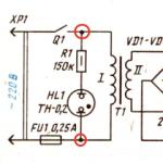 Designation of radioelements on diagrams
 Wood gasification Biomass resources for gasification