Methods and means of protecting the atmosphere. Ways and means of protecting the atmosphere and assessing their effectiveness
1
Content
I. Structure and composition of the atmosphere
II. Air pollution:
- The quality of the atmosphere and the features of its pollution;
The main chemical impurities that pollute the atmosphere.
- Basic methods of protecting the atmosphere from chemical impurities;
Classification of air purification systems and their parameters.
I. Structure and composition of the atmosphere
Atmosphere - This is the gaseous shell of the Earth, consisting of a mixture of various gases and extending to a height of more than 100 km. It has a layered structure, which includes a number of spheres and pauses located between them. The mass of the atmosphere is 5.91015 tons, the volume–
13.2-1020 m 3. The atmosphere plays a huge role in all natural processes and, first of all, regulates the thermal regime and general climatic conditions, and also protects humanity from harmful cosmic radiation.
The main gas components of the atmosphere are nitrogen (78%), oxygen (21%), argon (0.9%) and carbon dioxide (0.03%). The gas composition of the atmosphere changes with altitude. In the surface layer, due to anthropogenic impacts, the amount of carbon dioxide increases, and oxygen decreases. In some regions, as a result of economic activities, the amount of methane, nitrogen oxides and other gases in the atmosphere increases, causing such adverse phenomena as the greenhouse effect, ozone layer depletion, acid rain, and smog.
Atmospheric circulation affects the regime of rivers, soil and vegetation cover, as well as exogenous processes of relief formation. And finally the air–
a necessary condition for life on earth.
The densest layer of air adjacent to the earth's surface is called the troposphere. Its thickness is: at mid-latitudes 10-12 km, above sea level and at the poles 1-10 km, and at the equator 16-18 km.
Due to uneven heating by solar energy, powerful vertical air flows are formed in the atmosphere, and instability of its temperature, relative humidity, pressure, etc. is noted in the surface layer. But at the same time, the temperature in the troposphere is stable in height and decreases by 0.6°C for every 100 m in the range from +40 to -50°C. The troposphere contains up to 80% of all moisture present in the atmosphere, clouds are formed in it and all types of precipitation are formed, which, in essence, are air purifiers from impurities.
Above the troposphere is the stratosphere, and between them is the tropopause. The thickness of the stratosphere is about 40 km, the air in it is charged, its humidity is low, while the air temperature from the troposphere to a height of 30 km above sea level is constant (about -50 ° C), and then it gradually rises to + 10 ° C by altitude of 50 km. Under the influence of cosmic radiation and the short-wave part of the solar ultraviolet radiation, gas molecules in the stratosphere are ionized, resulting in the formation of ozone. The ozone layer, located up to 40 km, plays a very important role, protecting all life on Earth from ultraviolet rays.
The stratopause separates the stratosphere from the overlying mesosphere, where ozone is declining and the temperature at about 80 km above sea level is -70°C. The sharp temperature difference between the stratosphere and mesosphere is explained by the presence of the ozone layer.
II. Air pollution
1) The quality of the atmosphere and the features of its pollution
The quality of the atmosphere is understood as the totality of its properties that determine the degree of impact of physical, chemical and biological factors on people, flora and fauna, as well as on materials, structures and the environment as a whole. The quality of the atmosphere depends on its pollution, and the pollution itself can get into it from natural and anthropogenic sources. With the development of civilization, anthropogenic sources more and more predominate in atmospheric pollution.
Depending on the form of matter, pollution is divided into material (ingredient), energy (parametric) and material-energy. The former include mechanical, chemical and biological pollution, which are usually combined under the general concept of "impurities", the latter - thermal, acoustic, electromagnetic and ionizing radiation, as well as radiation in the optical range; to the third - radionuclides.
On a global scale, the greatest danger is the pollution of the atmosphere with impurities, since the air acts as an intermediary in the pollution of all other objects of nature, contributing to the spread of large masses of pollution over long distances. Airborne industrial emissions are polluting the oceans, acidifying soil and water, changing the climate and depleting the ozone layer.
Atmospheric pollution is understood as the introduction of impurities into it that are not contained in natural air or change the ratio between the ingredients of the natural composition of air.
The population of the Earth and the rate of its growth are the predetermining factors for increasing the intensity of pollution of all geospheres of the Earth, including the atmosphere, since with their increase, the volumes and rates of everything that is extracted, produced, consumed and sent to waste increase. The greatest air pollution is observed in cities where common pollutants are dust, sulfur dioxide, carbon monoxide, nitrogen dioxide, hydrogen sulfide, etc. In some cities, due to the peculiarities of industrial production, the air contains specific harmful substances, such as sulfuric and hydrochloric acid , styrene, benz (a) pyrene, soot, manganese, chromium, lead, methyl methacrylate. In total, there are several hundred different air pollutants in cities.
Of particular concern are atmospheric pollution by newly created substances and compounds. WHO notes that out of 105 known elements of the periodic table, 90 are used in industrial practice, and over 500 new chemical compounds have been obtained on their basis, almost 10% of which are harmful or especially harmful.
2) Major chemical impurities,
air pollutants
There are natural impurities, i.e. caused by natural processes, and anthropogenic, i.e. arising from the economic activities of mankind (Fig. 1). The level of atmospheric pollution by impurities from natural sources is background and has small deviations from the average level over time.
Rice. 1. Scheme of the processes of emissions of substances into the atmosphere and transformation
starting substances into products with subsequent precipitation in the form of precipitation
Anthropogenic pollution is distinguished by the variety of types of impurities and the numerous sources of their release. The most stable zones with high concentrations of pollution occur in places of active human activity. It has been established that every 10-12 years the volume of world industrial production doubles, and this is accompanied by approximately the same increase in the volume of pollutants emitted into the environment. For a number of pollutants, the growth rates of their emissions are much higher than average. These include aerosols of heavy and rare metals, synthetic compounds that do not exist and are not formed in nature, radioactive, bacteriological and other pollution.
Impurities enter the atmosphere in the form of gases, vapors, liquid and solid particles. Gases and vapors form mixtures with air, and liquid and solid particles form aerosols (dispersed systems), which are divided into dust (particle sizes over 1 µm), smoke (particle sizes less than 1 µm) and fog (liquid particle sizes less than 10 µm). ). Dust, in turn, can be coarse (particle size more than 50 microns), medium (50-10 microns) and fine (less than 10 microns). Depending on the size, liquid particles are divided into superfine fog (up to 0.5 µm), fine mist (0.5-3.0 µm), coarse mist (3-10 µm) and splashes (over 10 µm). Aerosols are often polydisperse; contain particles of various sizes.
The main chemical impurities that pollute the atmosphere are the following: carbon monoxide (CO), carbon dioxide (CO 2), sulfur dioxide (SO 2), nitrogen oxides, ozone, hydrocarbons, lead compounds, freons, industrial dust.
The main sources of anthropogenic aerosol air pollution are thermal power plants (TPP) that consume high-ash coal, processing plants, metallurgical, cement, magnesite and other plants. Aerosol particles from these sources are characterized by great chemical diversity. Most often, compounds of silicon, calcium and carbon are found in their composition, less often–
metal oxides: iron, magnesium, manganese, zinc, copper, nickel, lead, antimony, bismuth, selenium, arsenic, beryllium, cadmium, chromium, cobalt, molybdenum, and asbestos. An even greater variety is characteristic of organic dust, including aliphatic and aromatic hydrocarbons, acid salts. It is formed during the combustion of residual petroleum products, in the process of pyrolysis at oil refineries, petrochemical and other similar enterprises.
Industrial dumps are permanent sources of aerosol pollution.–
artificial embankments from redeposited material, mainly overburden, formed during mining or from waste from processing industries, thermal power plants. The production of cement and other building materials is also a source of air pollution with dust.
The combustion of hard coal, the production of cement, and the smelting of pig iron give a total emission of dust into the atmosphere equal to 170 million tons/year.
A significant part of aerosols is formed in the atmosphere when solid and liquid particles interact with each other or with water vapor. The dangerous anthropogenic factors that contribute to a serious deterioration in the quality of the atmosphere include its pollution with radioactive dust. The residence time of small particles in the lower layer of the troposphere is on average several days, and in the upper–
20-40 days. As for the particles that have entered the stratosphere, they can stay in it for up to a year, and sometimes more.
III. Methods and means of protecting the atmosphere
1) The main methods of protecting the atmosphere
from chemical impurities
All known methods and means of protecting the atmosphere from chemical impurities can be grouped into three groups.
The first group includes measures aimed at reducing the emission rate, i.e. decrease in the amount of emitted substance per unit of time. The second group includes measures aimed at protecting the atmosphere by processing and neutralizing harmful emissions with special purification systems. The third group includes measures to standardize emissions both at individual enterprises and devices, and in the region as a whole.
To reduce the power of emissions of chemical impurities into the atmosphere, the following are most widely used:
- replacing less environmentally friendly fuels with environmentally friendly ones;
fuel combustion according to special technology;
creation of closed production cycles.
Fuel combustion according to a special technology (Fig. 2) is carried out either in a fluidized (fluidized) bed, or by their preliminary gasification.
Rice. 2. Scheme of a thermal power plant using afterburning
flue gases and sorbent injection: 1 - steam turbine; 2 - burner;
3 - boiler; 4 - electroprecipitator; 5 - generator
To reduce the sulfur emission rate, solid, powdered or liquid fuels are burned in a fluidized bed, which is formed from solid particles of ash, sand or other substances (inert or reactive). Solid particles are blown into the passing gases, where they swirl, intensively mix and form a forced equilibrium flow, which generally has the properties of a liquid.
Coal and oil fuels are subjected to preliminary gasification, however, in practice, coal gasification is most often used. Since the produced and exhaust gases in power plants can be effectively cleaned, the concentrations of sulfur dioxide and particulate matter in their emissions will be minimal.
One of the promising ways to protect the atmosphere from chemical impurities is the introduction of closed production processes that minimize waste released into the atmosphere by reusing and consuming it, i.e. turning it into new products.
2) Classification of air purification systems and their parameters
According to the state of aggregation, air pollutants are divided into dust, mists and gas-vapour impurities. Industrial emissions containing suspended solids or liquids are two-phase systems. The continuous phase in the system is gases, and the dispersed–
solid particles or liquid droplets.
etc.................
Emissions from industrial enterprises are characterized by a wide variety of disperse composition and other physical and chemical properties. In this regard, various methods for their purification and types of gas and dust collectors have been developed - devices designed to purify emissions from pollutants.
Methods for cleaning industrial emissions from dust can be divided into two groups: dust collection methods "dry" way and dust collection methods "wet" way. Gas dedusting devices include: dust settling chambers, cyclones, porous filters, electrostatic precipitators, scrubbers, etc.
The most common dry dust collectors are cyclones various types.
They are used to trap flour and tobacco dust, ash formed during the combustion of fuel in boilers. The gas flow enters the cyclone through the nozzle 2 tangentially to the inner surface of the body 1 and performs a rotational-translational motion along the body. Under the action of centrifugal force, dust particles are thrown to the wall of the cyclone and, under the action of gravity, fall into the dust collection hopper 4, and the purified gas exits through the outlet pipe 3. For normal operation of the cyclone, its tightness is necessary, if the cyclone is not tight, then due to suction outside air, dust is carried out with the flow through the outlet pipe.
The tasks of cleaning gases from dust can be successfully solved by cylindrical (TsN-11, TsN-15, TsN-24, TsP-2) and conical (SK-TsN-34, SK-TsN-34M, SKD-TsN-33) cyclones, developed by the Research Institute for Industrial and Sanitary Gas Purification (NIIOGAZ). For normal operation, the excess pressure of gases entering the cyclones should not exceed 2500 Pa. At the same time, in order to avoid condensation of liquid vapors, t of the gas is selected 30 - 50 ° C above the dew point t, and according to the conditions of structural strength - not higher than 400 ° C. The performance of the cyclone depends on its diameter, increasing with the growth of the latter. The cleaning efficiency of cyclones of the TsN series decreases with an increase in the angle of entry into the cyclone. As the particle size increases and the cyclone diameter decreases, the purification efficiency increases. Cylindrical cyclones are designed to capture dry dust from aspiration systems and are recommended for use for pre-treatment of gases at the inlet of filters and electrostatic precipitators. Cyclones TsN-15 are made of carbon or low-alloy steel. The canonical cyclones of the SK series, designed for cleaning gases from soot, have increased efficiency compared to cyclones of the TsN type due to greater hydraulic resistance.
To clean large masses of gases, battery cyclones are used, consisting of a larger number of cyclone elements installed in parallel. Structurally, they are combined into one building and have a common gas supply and discharge. Operating experience of battery cyclones has shown that the cleaning efficiency of such cyclones is somewhat lower than the efficiency of individual elements due to the flow of gases between the cyclone elements. The domestic industry produces battery cyclones of the type BC-2, BCR-150u, etc.
Rotary dust collectors are centrifugal devices, which, simultaneously with the movement of air, purify it from a dust fraction larger than 5 microns. They are very compact, because. fan and dust collector are usually combined in one unit. As a result, during the installation and operation of such machines, no additional space is required to accommodate special dust-collecting devices when moving a dusty stream with an ordinary fan.
 The structural diagram of the simplest rotary type dust collector is shown in the figure. During operation of the fan wheel 1, dust particles are thrown to the wall of the spiral casing 2 due to centrifugal forces and move along it in the direction of the exhaust hole 3. The dust-enriched gas is discharged through a special dust inlet 3 into the dust bin, and the purified gas enters the exhaust pipe 4 .
To improve the efficiency of dust collectors of this design, it is necessary to increase the transfer speed of the cleaned flow in the spiral casing, but this leads to a sharp increase in the hydraulic resistance of the apparatus, or to reduce the radius of curvature of the casing spiral, but this reduces its performance. Such machines provide a sufficiently high efficiency of air purification while capturing relatively large dust particles - more than 20 - 40 microns.
More promising rotary type dust separators designed to purify air from particles > 5 μm in size are counterflow rotary dust separators (PRP). The dust separator consists of a hollow rotor 2 with a perforated surface built into the casing 1 and a fan wheel 3. The rotor and the fan wheel are mounted on a common shaft. During the operation of the dust separator, dusty air enters the casing, where it spins around the rotor. As a result of the rotation of the dust flow, centrifugal forces arise, under the influence of which the suspended dust particles tend to stand out from it in the radial direction. However, aerodynamic drag forces act on these particles in the opposite direction. Particles, the centrifugal force of which is greater than the force of aerodynamic resistance, are thrown to the walls of the casing and enter the hopper 4. The purified air is thrown out through the perforation of the rotor with the help of a fan.
The efficiency of PRP cleaning depends on the selected ratio of centrifugal and aerodynamic forces and theoretically can reach 1.
 Comparison of PRP with cyclones shows the advantages of rotary dust collectors. So, the overall dimensions of the cyclone are 3-4 times, and the specific energy consumption for cleaning 1000 m 3 of gas is 20-40% more than that of the PRP, all other things being equal. However, rotary dust collectors have not received wide distribution due to the relative complexity of the design and operation process compared to other devices for dry gas cleaning from mechanical impurities.
 To separate the gas stream into purified gas and dust-enriched gas, louvered dust separator. On the louvered grille 1, the gas flow with a flow rate Q is divided into two channels with a flow rate of Q 1 and Q 2 . Usually Q 1 \u003d (0.8-0.9) Q, and Q 2 \u003d (0.1-0.2) Q. The separation of dust particles from the main gas flow on the louvre occurs under the action of inertial forces arising from the rotation of the gas flow at the entrance to the louvre, as well as due to the effect of reflection of particles from the surface of the grate upon impact. The dust-enriched gas flow after the louvre is sent to the cyclone, where it is cleaned of particles, and is reintroduced into the pipeline behind the louvre. Louvred dust separators are simple in design and well assembled in gas ducts, providing a cleaning efficiency of 0.8 or more for particles larger than 20 microns. They are used to clean flue gases from coarse dust at t up to 450 - 600 o C.
Electrofilter. Electric purification is one of the most advanced types of gas purification from dust and fog particles suspended in them. This process is based on the impact ionization of gas in the zone of the corona discharge, the transfer of the ion charge to impurity particles and the deposition of the latter on the collecting and corona electrodes. Collecting electrodes 2 are connected to the positive pole of the rectifier 4 and grounded, and the corona electrodes are connected to the negative pole. Particles entering the electrostatic precipitator are connected to the positive pole of the rectifier 4 and grounded, and the corona electrodes are charged with impurity ions ana. usually already have a small charge obtained due to friction against the walls of pipelines and equipment. Thus, negatively charged particles move towards the collecting electrode, and positively charged particles settle on the negative corona electrode.
 Filters widely used for fine purification of gas emissions from impurities. The filtration process consists in retaining particles of impurities on porous partitions as they move through them. The filter is a housing 1, divided by a porous partition (filter-
element) 2 into two cavities. Contaminated gases enter the filter, which are cleaned when passing through the filter element. Particles of impurities settle on the inlet part of the porous partition and linger in the pores, forming layer 3 on the surface of the partition.
According to the type of partitions, filters are: - with granular layers (fixed freely poured granular materials) consisting of grains of various shapes, used to purify gases from large impurities. To purify gases from dusts of mechanical origin (from crushers, dryers, mills, etc.), gravel filters are more often used. Such filters are cheap, easy to operate and provide a high efficiency of cleaning (up to 0.99) of gases from coarse dust.
With flexible porous partitions (fabrics, felts, sponge rubber, polyurethane foam, etc.);
With semi-rigid porous partitions (knitted and woven meshes, pressed spirals and shavings, etc.);
With rigid porous partitions (porous ceramics, porous metals, etc.).
 The most widespread in the industry for dry cleaning of gas emissions from impurities are bag filters. The required number of sleeves 1 is installed in the filter housing 2, into the internal cavity of which dusty gas is supplied from the inlet pipe 5. Particles of pollution due to sieve and other effects settle in the pile and form a dust layer on the inner surface of the sleeves. The purified air leaves the filter through pipe 3. When the maximum allowable pressure drop across the filter is reached, it is disconnected from the system and regenerated by shaking the sleeves with their treatment by blowing with compressed gas. Regeneration is carried out by a special device 4.
Dust collectors of various types, including electrostatic precipitators, are used at elevated concentrations of impurities in the air. Filters are used for fine air purification with impurity concentrations not exceeding 50 mg/m 3, if the required fine air purification occurs at high initial concentrations of impurities, then purification is carried out in a system of series-connected dust collectors and filters.
Apparatus wet cleaning gases are widespread, tk. are characterized by high cleaning efficiency from fine dusts with d h ≥ (0.3-1.0) μm, as well as the possibility of cleaning dust from hot and explosive gases. However, wet dust collectors have a number of disadvantages that limit their scope: sludge, which requires special systems for its processing; removal of moisture into the atmosphere and the formation of deposits in the outlet gas ducts when the gases are cooled to the dew point temperature; the need to create circulating systems for supplying water to the dust collector.
 Wet cleaners work on the principle of deposition of dust particles on the surface of either liquid droplets or liquid films. The sedimentation of dust particles on the liquid occurs under the action of inertia forces and Brownian motion.
Among the wet cleaning devices with the deposition of dust particles on the surface of the drops, in practice, more applicable Venturi scrubbers. The main part of the scrubber is a Venturi nozzle 2, into the confuser part of which a dusty gas flow is supplied and liquid is supplied through centrifugal nozzles 1 for irrigation. In the confuser part of the nozzle, the gas is accelerated from the input velocity of 15–20 m/s to the velocity in the narrow section of the nozzle of 30–200 m/s, and in the diffuser part of the nozzle, the flow is decelerated to a velocity of 15–20 m/s and is fed into the drop catcher 3. The drop catcher is usually made in the form of a once-through cyclone. Venturi scrubbers provide high cleaning efficiency for aerosols with an average particle size of 1-2 microns at an initial impurity concentration of up to 100 g/m 3 .
 Wet dust collectors include Bubble-foam dust collectors with dip and overflow gratings. In such devices, the gas for purification enters under the grate 3, passes through the holes in the grate and, passing through the layer of liquid or foam 2, under pressure, is cleaned of part of the dust due to the deposition of particles on the inner surface of the gas bubbles. The mode of operation of the devices depends on the speed of air supply under the grate. At a speed of up to 1 m/s, a bubbling mode of operation of the apparatus is observed. A further increase in the gas velocity in the body of the apparatus from 1 to 2-2.5 m/s is accompanied by the appearance of a foam layer above the liquid, which leads to an increase in the efficiency of gas purification and spray entrainment from the apparatus. Modern bubbling-foam devices ensure the efficiency of gas purification from fine dust ≈ 0.95-0.96 at specific water consumption of 0.4-0.5 l/m 3 . But these apparatuses are very sensitive to non-uniformity of gas supply under failed grates, which leads to local blowing off of the liquid film from the grate. Grids are prone to clogging.
Methods for cleaning industrial emissions from gaseous pollutants are divided into five main groups according to the nature of the course of physical and chemical processes: washing emissions with solvents of impurities (absorption); flushing of emissions with solutions of reagents that chemically bind impurities (chemisorption); absorption of gaseous impurities by solid active substances (adsorption); thermal neutralization of exhaust gases and the use of catalytic conversion.
absorption method. In gas emission cleaning techniques, the absorption process is often referred to as scrubber process. Purification of gas emissions by the absorption method consists in separating a gas-air mixture into its constituent parts by absorbing one or more gas components (absorbates) of this mixture with a liquid absorbent (absorbent) to form a solution.
The driving force here is the concentration gradient at the gas-liquid phase boundary. The component of the gas-air mixture (absorbate) dissolved in the liquid penetrates into the inner layers of the absorbent due to diffusion. The process proceeds the faster, the larger the phase separation surface, the turbulence of the flows and the diffusion coefficients, i.e. in the design of absorbers, special attention should be paid to organizing the contact of the gas flow with the liquid solvent and the choice of the absorbing liquid (absorbent).
The decisive condition for the choice of absorbent is the solubility of the extracted component in it and its dependence on temperature and pressure. If the solubility of gases at 0°C and a partial pressure of 101.3 kPa is hundreds of grams per 1 kg of solvent, then such gases are called highly soluble.
The organization of the contact of the gas stream with the liquid solvent is carried out either by passing the gas through the packed column, or by spraying the liquid, or by bubbling the gas through the absorbing liquid layer. Depending on the implemented method of gas-liquid contact, there are: packed towers: nozzle and centrifugal scrubbers, Venturi scrubbers; bubbling-foam and other scrubbers.
The general arrangement of the upwind packing tower is shown in the figure. The polluted gas enters the bottom of the tower, while the purified gas leaves it through the top, where, with the help of one or more sprinklers 2
a pure absorbent is introduced, and the spent solution is taken from the bottom. The purified gas is usually vented to the atmosphere.  The liquid leaving the absorber is regenerated, desorbing the contaminant, and returned to the process or removed as a waste (by-product). Chemically inert packing 1, which fills the internal cavity of the column, is designed to increase the surface of the liquid spreading over it in the form of a film. Bodies of different geometric shapes are used as packings, each of which is characterized by its own specific surface area and resistance to the movement of the gas flow.
The choice of purification method is determined by a technical and economic calculation and depends on: the concentration of the pollutant in the purified gas and the required degree of purification, depending on the background pollution of the atmosphere in the given region; volumes of purified gases and their temperature; the presence of accompanying gaseous impurities and dust; the need for certain disposal products and the availability of the required sorbent; the size of the areas available for the construction of a gas treatment plant; availability of the necessary catalyst, natural gas, etc.
When choosing instrumentation for new technological processes, as well as when reconstructing existing gas cleaning plants, it is necessary to be guided by the following requirements: maximum efficiency of the cleaning process in a wide range of load characteristics at low energy costs; simplicity of design and maintenance; compactness and the possibility of manufacturing devices or individual units from polymeric materials; the possibility of working on circulating irrigation or on self-irrigation. The main principle that should be the basis for the design of treatment facilities is the maximum possible retention of harmful substances, heat and their return to the technological process.

Task #2: Equipment is installed at the grain processing plant, which is a source of grain dust emission. To remove it from the working area, the equipment is equipped with an aspiration system. In order to clean the air before it is released into the atmosphere, a dust-collecting installation is used, consisting of a single or battery cyclone.
Determine: 1. The maximum allowable emission of grain dust.
2. Select the design of the dust collection plant, consisting of cyclones of the Research Institute for Industrial and Sanitary Gas Cleaning (NII OGAZ), determine its efficiency according to the schedule and calculate the dust concentration at the inlet and outlet of the cyclone.
Emission source height H = 15 m,
The speed of the exit of the gas-air mixture from the source w about = 6 m/s,
Spring mouth diameter D = 0.5 m,
Emission temperature T g \u003d 25 ° C,
Ambient temperature T in \u003d _ -14 o C,
Average size of dust particles d h = 4 µm,
MPC grain dust = 0.5 mg / m 3,
Background concentration of grain dust С f = 0.1 mg/m 3 ,
The company is located in the Moscow region,
The terrain is calm.
Decision 1. Determine the MPE of grain dust:
M pdv = ![]() , mg / m 3
, mg / m 3
from the definition of MPE we have: C m \u003d C pdc - C f \u003d 0.5-0.1 \u003d 0.4 mg / m 3,
The flow rate of the gas-air mixture V 1 = ![]() ,
,
DT \u003d T g - T in \u003d 25 - (-14) \u003d 39 o C,
determine the emission parameters: f =1000 ![]() , then
, then
m = 1/(0.67+0.1 + 0.34 ) = 1/(0.67 + 0.1 +0.34 ) = 0.8 .
V m = 0.65 ![]() , then
, then
n \u003d 0.532V m 2 - 2.13V m + 3.13 \u003d 0.532 × 0.94 2 - 2.13 × 0.94 + 3.13 \u003d 1.59, and
M pdv = ![]() g/s.
g/s.
2. Selection of a treatment plant and determination of its parameters.
a) The choice of dust collecting installation is made according to catalogs and tables (“Ventilation, air conditioning and air purification at food industry enterprises” by E.A. Shtokman, V.A. Shilov, E.E. Novgorodsky et al., M., 1997). The selection criterion is the performance of the cyclone, i.e. the flow rate of the gas-air mixture, at which the cyclone has a maximum efficiency. When solving the problem, we will use the table:
The first line contains data for a single cyclone, the second line for a battery cyclone.
If the calculated performance is in the range between the tabular values, then the design of the dust collection plant with the nearest higher performance is selected.
We determine the hourly productivity of the treatment plant:
V h \u003d V 1 × 3600 \u003d 1.18 × 3600 \u003d 4250 m 3 / h
According to the table, according to the nearest larger value V h = 4500 m 3 / h, we select a dust collecting installation in the form of a single cyclone TsN-11 with a diameter of 800 mm.
b) According to the graph in Fig. 1 of the application, the efficiency of the dust collection plant with an average dust particle diameter of 4 μm is h och = 70%.
c) Determine the concentration of dust at the outlet of the cyclone (at the mouth of the source):
C out = ![]()
The maximum concentration of dust in the cleaned air C in is determined by:
C in = ![]() .
.
If the actual value of C in is greater than 1695 mg/m 3 , then the dust collection plant will not give the desired effect. In this case, more advanced cleaning methods must be used.
3. Determine the pollution indicator
P = ![]() ,
,
where M is the mass of pollutant emission, g/s,
The pollution indicator shows how much clean air is needed to "dissolve" the pollutant emitted by the source per unit of time, up to the MPC, taking into account the background concentration.
P = ![]() .
.
The annual pollution index is the total pollution index. To determine it, we find the mass of grain dust emissions per year:
M year \u003d 3.6 × M MPE × T × d × 10 -3 \u003d 3.6 × 0.6 × 8 × 250 × 10 -3 \u003d 4.32 t / year, then
åR = ![]() .
.
The pollution index is necessary for the comparative evaluation of different emission sources.
For comparison, let's calculate EP for sulfur dioxide from the previous problem for the same period of time:
M year \u003d 3.6 × M MPE × T × d × 10 -3 \u003d 3.6 × 0.71 × 8 × 250 × 10 -3 \u003d 5.11 t / year, then
åR = ![]()
And in conclusion, it is necessary to draw a sketch of the selected cyclone according to the dimensions given in the appendix, on an arbitrary scale.
Pollution control. Payment for environmental damage.
When calculating the amount of pollutant, i.e. ejection masses are determined by two quantities: gross emission (t/year) and maximum single emission (g/s). The gross emission value is used for the general assessment of air pollution by a given source or group of sources, and is also the basis for calculating payments for pollution of the environmental protection system.
The maximum one-time emission allows assessing the state of atmospheric air pollution at a given point in time and is the initial value for calculating the maximum surface concentration of a pollutant and its dispersion in the atmosphere.
When developing measures to reduce emissions of pollutants into the atmosphere, it is necessary to know what contribution each source makes to the overall picture of atmospheric air pollution in the area where the enterprise is located.
TSV - temporarily agreed release. If at a given enterprise or a group of enterprises located in the same area (S F is large), the MPE value for objective reasons cannot be achieved at the present time, then in agreement with the body exercising state control over the protection of the atmosphere from pollution, the the adoption of a phased reduction in emissions to MPE values and the development of specific measures for this.
Payments are collected for the following types of harmful effects on the environment: - emission of pollutants into the atmosphere from stationary and mobile sources;
Discharge of pollutants into surface and underground water bodies;
Waste disposal;
Dr. types of harmful effects (noise, vibration, electromagnetic and radiation effects, etc.).
There are two types of basic payment standards:
a) for emissions, discharges of pollutants and waste disposal within acceptable limits
b) for emissions, discharges of pollutants and waste disposal within the established limits (temporarily agreed standards).
Basic payment rates are established for each pollutant (waste) ingredient, taking into account the degree of their danger to the environmental protection system and public health.
The rates of pollution charges for environmental pollution are specified in the Decree of the Government of the Russian Federation dated June 12, 2003 No. No. 344 "On the standards of payment for emissions of pollutants into the atmospheric air by stationary and mobile sources, discharges of pollutants into surface and underground water bodies, disposal of production and consumption waste" for 1 ton in rubles:
Payment for emissions of pollutants that do not exceed the standards established for the nature user:
П = С Н × М Ф, with М Ф £ М Н,
where МФ is the actual emission of a pollutant, t/year;
МН is the maximum allowable standard for this pollutant;
СН is the rate of payment for the emission of 1 ton of this pollutant within the limits of permissible emission standards, rub/t.
Payment for pollutant emissions within the established emission limits:
P \u003d C L (M F - M N) + C N M N, with M N< М Ф < М Л, где
C L - the rate of payment for the emission of 1 ton of a pollutant within the established emission limits, rub / t;
M L is the established limit for the emission of a given pollutant, t/year.
Payment for excess emission of pollutants:
P \u003d 5 × S L (M F - M L) + S L (M L - M N) + S N × M N, with M F > M L.
Payment for the emission of pollutants, when the standards for the emission of pollutants or a fine are not established for the user of nature:
P = 5 × S L × M F
Payments for maximum permissible emissions, discharges of pollutants, waste disposal are carried out at the expense of the cost of products (works, services), and for exceeding them - at the expense of the profit remaining at the disposal of the nature user.
Payments for environmental pollution are received by:
19% to the federal budget,
81% to the budget of the subject of the Federation.
Task No. 3. "Calculation of technological emissions and payment for environmental pollution on the example of a bakery"
The bulk of pollutants, such as ethyl alcohol, acetic acid, acetaldehyde, are formed in baking chambers, from where they are removed through exhaust ducts due to natural draft or emitted into the atmosphere through metal pipes or shafts at least 10-15 m high. Emissions of flour dust mainly occur in flour warehouses. Oxides of nitrogen and carbon are formed when natural gas is burned in baking chambers.
Initial data:
1. Annual output of the bakery in Moscow - 20,000 tons / year of bakery products, incl. bakery products from wheat flour - 8,000 t/year, bakery products from rye flour - 5,000 t/year, bakery products from mixed rolls - 7,000 t/year.
2. Recipe roll: 30% - wheat flour and 70% - rye flour
3. Flour storage condition - bulk.
4. Fuel in furnaces and boilers - natural gas.
I. Technological emissions of the bakery.
II. Payment for air pollution, if MPE for:
Ethyl alcohol - 21 tons / year,
Acetic acid - 1.5 t/year (SSV - 2.6 t/year),
Acetic aldehyde - 1 t / year,
Flour dust - 0.5 t / year,
Nitrogen oxides - 6.2 t / year,
Carbon oxides - 6 t/year.
1. In accordance with the methodology of the All-Russian Research Institute of KhP, technological emissions during baking of bakery products are determined by the method of specific indicators:
M \u003d B × m, where
M is the amount of pollutant emissions in kg per unit of time,
B - production output in tons for the same period of time,
m is the specific indicator of pollutant emissions per unit of output, kg/t.
Specific emissions of pollutants in kg/t of finished products.
1. Ethyl alcohol: bakery products made from wheat flour - 1.1 kg / t,
bakery products made from rye flour - 0.98 kg / t.
2. Acetic acid: bakery products made from wheat flour - 0.1 kg / t,
bakery products made from rye flour – 0.2 kg/t.
3. Acetic aldehyde - 0.04 kg / t.
4. Flour dust - 0.024 kg/t (for bulk storage of flour), 0.043 kg/t (for container storage of flour).
5. Nitrogen oxides - 0.31 kg / t.
6. Carbon oxides - 0.3 kg/t.
I. Calculation of technological emissions:
1. Ethyl alcohol:
M 1 \u003d 8000 × 1.1 \u003d 8800 kg / year;
M 2 \u003d 5000 × 0.98 \u003d 4900 kg / year;
M 3 \u003d 7000 (1.1 × 0.3 + 0.98 × 0.7) \u003d 7133 kg / year;
total emission M \u003d M 1 + M 2 + M 3 \u003d 8800 + 4900 + 7133 \u003d 20913 kg / year.
2. Acetic acid:
Bakery products made from wheat flour
M 1 \u003d 8000 × 0.1 \u003d 800 kg / year;
Bakery products made from rye flour
M 2 \u003d 5000 × 0.2 \u003d 1000 kg / year;
Bakery products from mixed rolls
M 3 \u003d 7000 (0.1 × 0.3 + 0.2 × 0.7) \u003d 1190 kg / year,
total emission M \u003d M 1 + M 2 + M 3 \u003d 800 + 1000 + 1190 \u003d 2990 kg / year.
3. Acetic aldehyde М = 20000 × 0.04 = 800 kg/year.
4. Flour dust М = 20000 × 0.024 = 480 kg/year.
5. Nitrogen oxides М = 20000 × 0.31 = 6200 kg/year.
6. Carbon oxides М = 20000 × 0.3 = 6000 kg/year.
II. Calculation of payment for pollution of the environmental protection system.
1. Ethyl alcohol: M N = 21 t / year, M F = 20.913 t / year Þ P = C N × M f = 0.4 × 20.913 = 8.365 rubles.
2. Acetic acid: M N \u003d 1.5 t / year, M L \u003d 2.6 t / year, M F \u003d 2.99 t / year Þ P \u003d 5C L (M F -M L) + C L ( M L - M N) + C N × M N =
5 × 175 × (2.99-2.6) + 175 × (2.6 - 1.5) + 35 × 1.5 = 586.25 rubles.
3. Acetic aldehyde: M H \u003d 1 t / year, M F \u003d 0.8 t / year Þ P \u003d C H × M F \u003d 68 × 0.8 \u003d 54.4 rubles.
4. Flour dust: M N = 0.5 t/year, M F = 0.48 t/year Þ P = C N × M F = 13.7 × 0.48 = 6.576 rubles.
5. Nitrogen oxide: M N = 6.2 t / year, M F = 6.2 t / year Þ P = C N × M F = 35 × 6.2 = 217 rubles.
6. Carbon oxide: М Н = 6 t/year, М Ф = 6 t/year Þ
P \u003d C N × M F \u003d 0.6 × 6 \u003d 3.6 rubles.
The coefficient taking into account environmental factors for the Central region of the Russian Federation = 1.9 for atmospheric air, for the city the coefficient is 1.2.
åP \u003d 876.191 1.9 1.2 \u003d 1997.72 rubles
CONTROL TASKS.
Exercise 1
| option number | Productivity of the boiler house Q about, MJ/h | Source height H, m | Mouth diameter D, m | Background concentration of SO 2 C f, mg/m 3 |
| 0,59 | 0,004 | |||
| 0,59 | 0,005 | |||
| 0,6 | 0,006 | |||
| 0,61 | 0,007 | |||
| 0,62 | 0,008 | |||
| 0,63 | 0,004 | |||
| 0,64 | 0,005 | |||
| 0,65 | 0,006 | |||
| 0,66 | 0,007 | |||
| 0,67 | 0,008 | |||
| 0,68 | 0,004 | |||
| 0,69 | 0,005 | |||
| 0,7 | 0,006 | |||
| 0,71 | 0,007 | |||
| 0,72 | 0,008 | |||
| 0,73 | 0,004 | |||
| 0,74 | 0,005 | |||
| 0,75 | 0,006 | |||
| 0,76 | 0,007 | |||
| 0,77 | 0,008 | |||
| 0,78 | 0,004 | |||
| 0,79 | 0,005 | |||
| 0,8 | 0,006 | |||
| 0,81 | 0,007 | |||
| 0,82 | 0,008 | |||
| 0,83 | 0,004 | |||
| 0,84 | 0,005 | |||
| 0,85 | 0,006 | |||
| 0,86 | 0,007 | |||
| 0,87 | 0,004 | |||
| 0,88 | 0,005 | |||
| 0,89 | 0,006 |
Send your good work in the knowledge base is simple. Use the form below
Students, graduate students, young scientists who use the knowledge base in their studies and work will be very grateful to you.
Hosted at http://www.allbest.ru/
Ministry of Education and Science of the Russian Federation
Federal State Budgetary Educational Institution
higher professional education
"Don State Technical University" (DSTU)
Ways and means of protecting the atmosphere and assessing their effectiveness
Performed:
student of MTS group IS 121
Kolemasova A.S.
Rostov-on-Don
Introduction
2. Mechanical cleaning of gases
Sources used
Introduction
The atmosphere is characterized by extremely high dynamism, due to both the rapid movement of air masses in the lateral and vertical directions, and high speeds, a variety of physical and chemical reactions occurring in it. The atmosphere is seen as a huge "chemical cauldron", which is influenced by numerous and variable anthropogenic and natural factors. Gases and aerosols released into the atmosphere are highly reactive. Dust and soot generated during fuel combustion, forest fires absorb heavy metals and radionuclides and, when deposited on the surface, can pollute vast areas and enter the human body through the respiratory system.
Atmospheric pollution is the direct or indirect introduction of any substance into it in such a quantity that affects the quality and composition of the outdoor air, harming people, living and inanimate nature, ecosystems, building materials, natural resources - the entire environment.
Purification of air from impurities.
To protect the atmosphere from negative anthropogenic impact, the following measures are used:
Ecologization of technological processes;
Purification of gas emissions from harmful impurities;
Dissipation of gaseous emissions in the atmosphere;
Arrangement of sanitary protection zones, architectural and planning solutions.
Waste-free and low-waste technology.
Ecologization of technological processes is the creation of closed technological cycles, waste-free and low-waste technologies that exclude harmful pollutants from entering the atmosphere.
The most reliable and most economical way to protect the biosphere from harmful gas emissions is the transition to waste-free production, or waste-free technologies. The term "wasteless technology" was first proposed by Academician N.N. Semenov. It implies the creation of optimal technological systems with closed material and energy flows. Such production should not have wastewater, harmful emissions into the atmosphere and solid waste, and should not consume water from natural reservoirs. That is, they understand the principle of organization and functioning of industries, with the rational use of all components of raw materials and energy in a closed cycle: (primary raw materials - production - consumption - secondary raw materials).
Of course, the concept of "non-waste production" is somewhat arbitrary; this is an ideal production model, since in real conditions it is impossible to completely eliminate waste and get rid of the impact of production on the environment. More precisely, such systems should be called low-waste systems, giving minimal emissions, in which damage to natural ecosystems will be minimal. Low-waste technology is an intermediate step in the creation of waste-free production.
1. Development of non-waste technologies
At present, several main directions for the protection of the biosphere have been identified, which ultimately lead to the creation of waste-free technologies:
1) development and implementation of fundamentally new technological processes and systems operating in a closed cycle, which make it possible to exclude the formation of the main amount of waste;
2) processing of production and consumption waste as secondary raw materials;
3) creation of territorial-industrial complexes with a closed structure of material flows of raw materials and waste within the complex.
The importance of the economical and rational use of natural resources does not require justification. The need for raw materials is constantly growing in the world, the production of which is becoming more and more expensive. Being a cross-sectoral problem, the development of low-waste and waste-free technologies and the rational use of secondary resources require cross-sectoral decisions.
The development and implementation of fundamentally new technological processes and systems operating in a closed cycle, which make it possible to exclude the formation of the main amount of waste, is the main direction of technical progress.
Purification of gas emissions from harmful impurities
Gas emissions are classified according to the organization of removal and control - into organized and unorganized, according to temperature into heated and cold.
An organized industrial emission is an emission entering the atmosphere through specially constructed gas ducts, air ducts, pipes.
Unorganized refers to industrial emissions that enter the atmosphere in the form of non-directional gas flows as a result of equipment leaks. Absence or unsatisfactory operation of gas suction equipment at the places of loading, unloading and storage of the product.
To reduce air pollution from industrial emissions, gas purification systems are used. Purification of gases refers to the separation from gas or the transformation into a harmless state of a pollutant coming from an industrial source.
2. Mechanical cleaning of gases
It includes dry and wet methods.
Purification of gases in dry mechanical dust collectors.
Dry mechanical dust collectors include devices that use various deposition mechanisms: gravitational (dust settling chamber), inertial (chambers in which dust is deposited as a result of a change in the direction of the gas flow or the installation of an obstacle in its path) and centrifugal.
Gravitational settling is based on the settling of suspended particles under the action of gravity when a dusty gas moves at low speed without changing the flow direction. The process is carried out in settling gas ducts and dust settling chambers (Fig. 1). To reduce the height of particle settling in the settling chambers, a plurality of horizontal shelves are installed at a distance of 40-100 mm, breaking the gas flow into flat jets. Gravitational settling is effective only for large particles with a diameter of more than 50-100 microns, and the degree of purification is not higher than 40-50%. The method is suitable only for preliminary, coarse purification of gases.
Dust settling chambers (Fig. 1). The sedimentation of particles suspended in the gas flow in the dust settling chambers occurs under the action of gravity. The simplest designs of apparatuses of this type are settling gas ducts, sometimes provided with vertical baffles for better sedimentation of solid particles. Multi-shelf dust settling chambers are widely used for cleaning hot furnace gases.
The dust settling chamber consists of: 1 - inlet pipe; 2 - outlet pipe; 3 - body; 4 - hopper of suspended particles.
Inertial settling is based on the tendency of suspended particles to maintain their original direction of motion when the direction of the gas flow changes. Among the inertial devices, louvered dust collectors with a large number of slots (louvers) are most often used. The gases are dedusted, leaving through the cracks and changing the direction of movement, the gas velocity at the inlet to the apparatus is 10-15 m/s. The hydraulic resistance of the apparatus is 100-400 Pa (10-40 mm of water column). Dust particles with d< 20 мкм в жалюзийных аппаратах не улавливаются. Степень очистки в зависимости от дисперсности частиц составляет 20-70%. Инерционный метод можно применять лишь для грубой очистки газа. Помимо малой эффективности недостаток этого метода - быстрое истирание или забивание щелей.
These devices are easy to manufacture and operate, they are widely used in industry. But the capture efficiency is not always sufficient.
Centrifugal methods of gas purification are based on the action of centrifugal force arising from the rotation of the gas stream being cleaned in the purification apparatus or from the rotation of parts of the apparatus itself. Cyclones (Fig. 2) of various types are used as centrifugal dust cleaners: battery cyclones, rotating dust collectors (rotoclones), etc. Cyclones are most often used in industry for the deposition of solid aerosols. Cyclones are characterized by high gas productivity, simple design, and reliable operation. The degree of dust removal depends on the size of the particles. For cyclones of high productivity, in particular battery cyclones (with a capacity of more than 20,000 m 3 /h), the degree of purification is about 90% with a particle diameter d > 30 μm. For particles with d = 5–30 µm, the degree of purification is reduced to 80%, and for d == 2–5 µm, it is less than 40%.
atmosphere industrial waste cleaning
On fig. 2, air is introduced tangentially into the inlet pipe (4) of the cyclone, which is a swirling apparatus. The rotating flow formed here descends along the annular space formed by the cylindrical part of the cyclone (3) and the exhaust pipe (5) into its conical part (2), and then, continuing to rotate, exits the cyclone through the exhaust pipe. (1) - dust outlet.
Aerodynamic forces bend the trajectory of the particles. During the rotationally downward movement of the dusty flow, dust particles reach the inner surface of the cylinder and are separated from the flow. Under the influence of gravity and the entraining action of the flow, the separated particles descend and pass through the dust outlet into the hopper.
A higher degree of air purification from dust compared to a dry cyclone can be obtained in wet-type dust collectors (Fig. 3), in which dust is captured as a result of contact of particles with a wetting liquid. This contact can be carried out on wetted walls flowed by air, on drops or on the free surface of water.
On fig. 3 shows a water film cyclone. Dusty air is supplied through the air duct (5) to the lower part of the apparatus tangentially at a speed of 15-21 m/s. The swirling air flow, moving upwards, encounters a film of water flowing down the surface of the cylinder (2). The purified air is discharged from the upper part of the apparatus (4) also tangentially in the direction of rotation of the air flow. The water film cyclone does not have an exhaust pipe characteristic of dry cyclones, which makes it possible to reduce the diameter of its cylindrical part.
The inner surface of the cyclone is continuously irrigated with water from nozzles (3) placed around the circumference. The water film on the inner surface of the cyclone must be continuous, so the nozzles are installed so that the water jets are directed tangentially to the surface of the cylinder in the direction of rotation of the air flow. The dust captured by the water film flows together with water into the conical part of the cyclone and is removed through the branch pipe (1) immersed in the water of the sump. The settled water is again fed into the cyclone. The air velocity at the cyclone inlet is 15-20 m/s. The efficiency of cyclones with a water film is 88-89% for dust with a particle size of up to 5 microns, and 95-100% for dust with larger particles.
Other types of centrifugal dust collector are rotoclone (fig. 4) and scrubber (fig. 5).
Cyclone devices are the most common in industry, since they have no moving parts in the device and high reliability at gas temperatures up to 500 0 C, dry dust collection, almost constant hydraulic resistance of the device, ease of manufacture, high degree of purification.
Rice. 4 - Gas scrubber with a central downpipe: 1 - inlet pipe; 2 - reservoir with liquid; 3 - nozzle
The dusty gas enters through the central tube, hits the surface of the liquid at high speed and, turning by 180°, is removed from the apparatus. Dust particles penetrate the liquid upon impact and are periodically or continuously discharged from the apparatus in the form of sludge.
Disadvantages: high hydraulic resistance 1250-1500 Pa, poor capture of particles smaller than 5 microns.
Hollow nozzle scrubbers are round or rectangular columns in which contact is made between gases and liquid droplets sprayed by nozzles. According to the direction of movement of gases and liquids, hollow scrubbers are divided into counter-flow, direct-flow and with a transverse liquid supply. In wet dedusting, apparatuses with counterdirectional movement of gases and liquids are usually used, less often with a transverse supply of liquid. Single-flow hollow scrubbers are widely used in the evaporative cooling of gases.
In a countercurrent scrubber (Fig. 5.), drops from the nozzles fall towards the dusty gas flow. The droplets must be large enough not to be carried away by the gas flow, the velocity of which is usually vg = 0.61.2 m/s. Therefore, coarse spray nozzles are usually installed in gas scrubbers, operating at a pressure of 0.3-0.4 MPa. At gas velocities of more than 5 m/s, a drop eliminator must be installed after the gas scrubber.
Rice. 5 - Hollow nozzle scrubber: 1 - body; 2 - gas distribution grid; 3 - nozzles
The height of the apparatus is usually 2.5 times its diameter (H = 2.5D). Nozzles are installed in the apparatus in one or more sections: sometimes in rows (up to 14-16 in cross section), sometimes only along the axis of the apparatus. The nozzle spray can be directed vertically from top to bottom or at some angle to the horizontal plane. When the nozzles are located in several tiers, a combined installation of atomizers is possible: part of the torches is directed along the flue gases, the other part - in the opposite direction. For a better distribution of gases over the cross section of the apparatus, a gas distribution grate is installed in the lower part of the scrubber.
Hollow jet scrubbers are widely used for coarse dust removal, as well as gas cooling and air conditioning. The specific flow rate of the liquid is low - from 0.5 to 8 l/m 3 of purified gas.
Filters are also used to purify gases. Filtration is based on the passage of the purified gas through various filter materials. Filtering baffles consist of fibrous or granular elements and are conventionally divided into the following types.
Flexible porous partitions - fabric materials made of natural, synthetic or mineral fibers, non-woven fibrous materials (felt, paper, cardboard) cellular sheets (foam rubber, polyurethane foam, membrane filters).
Filtration is a very common technique for fine gas purification. Its advantages are the comparatively low cost of equipment (with the exception of metal-ceramic filters) and the high efficiency of fine purification. Disadvantages of filtration high hydraulic resistance and rapid clogging of the filter material with dust.
3. Purification of emissions of gaseous substances, industrial enterprises
At present, when waste-free technology is in its infancy and there are no completely waste-free enterprises yet, the main task of gas cleaning is to bring the content of toxic impurities in gas impurities to the maximum permissible concentrations (MPC) established by sanitary standards.
Industrial methods for cleaning gas emissions from gaseous and vaporous toxic impurities can be divided into five main groups:
1. Absorption method - consists in the absorption of individual components of a gaseous mixture by an absorbent (absorber), which is a liquid.
Absorbents used in industry are evaluated according to the following indicators:
1) absorption capacity, i.e. solubility of the extracted component in the absorber depending on temperature and pressure;
2) selectivity, characterized by the ratio of the solubilities of the separated gases and their absorption rates;
3) minimum vapor pressure to avoid contamination of the purified gas with absorbent vapors;
4) cheapness;
5) no corrosive effect on the equipment.
Water, solutions of ammonia, caustic and carbonate alkalis, manganese salts, ethanolamines, oils, suspensions of calcium hydroxide, manganese and magnesium oxides, magnesium sulfate, etc. are used as absorbents. For example, to purify gases from ammonia, hydrogen chloride and hydrogen fluoride as an absorbent water is used, for trapping water vapor - sulfuric acid, for trapping aromatic hydrocarbons - oils.
Absorption cleaning is a continuous and, as a rule, cyclical process, since the absorption of impurities is usually accompanied by the regeneration of the absorption solution and its return at the beginning of the cleaning cycle. During physical absorption, the regeneration of the absorbent is carried out by heating and lowering the pressure, as a result of which the absorbed gaseous admixture is desorbed and concentrated.
To implement the cleaning process, absorbers of various designs (film, packed, tubular, etc.) are used. The most common packed scrubber is used to clean gases from sulfur dioxide, hydrogen sulfide, hydrogen chloride, chlorine, carbon monoxide and dioxide, phenols, etc. In packed scrubbers, the rate of mass transfer processes is low due to the low-intensity hydrodynamic regime of these reactors operating at a gas velocity of 0.02–0.7 m/s. The volumes of the apparatuses are therefore large and the installations are cumbersome.
Rice. 6 - Packed scrubber with transverse irrigation: 1 - body; 2 - nozzles; 3 - irrigation device; 4 - support grid; 5 - nozzle; 6 - sludge collector
Absorption methods are characterized by the continuity and versatility of the process, economy and the ability to extract large amounts of impurities from gases. The disadvantage of this method is that packed scrubbers, bubbling and even foam apparatuses provide a sufficiently high degree of extraction of harmful impurities (up to MPC) and complete regeneration of absorbers only with a large number of purification stages. Therefore, wet treatment flowsheets are usually complex, multi-stage, and treatment reactors (especially scrubbers) have large volumes.
Any process of wet absorption purification of exhaust gases from gaseous and vaporous impurities is expedient only if it is cyclical and waste-free. But cyclic wet cleaning systems are competitive only when they are combined with dust cleaning and gas cooling.
2. Chemisorption method - based on the absorption of gases and vapors by solid and liquid absorbers, resulting in the formation of low volatile and low soluble compounds. Most chemisorption gas cleaning processes are reversible; As the temperature of the absorption solution rises, the chemical compounds formed during chemisorption decompose with the regeneration of the active components of the absorption solution and with the desorption of the admixture absorbed from the gas. This technique underlies the regeneration of chemisorbents in cyclic gas cleaning systems. Chemisorption is especially applicable for fine purification of gases at a relatively low initial impurity concentration.
3. The adsorption method is based on the capture of harmful gas impurities by the surface of solids, highly porous materials with a developed specific surface.
Adsorption methods are used for various technological purposes - the separation of gas-vapor mixtures into components with separation of fractions, gas drying and for sanitary cleaning of gas exhausts. Recently, adsorption methods have come to the fore as a reliable means of protecting the atmosphere from toxic gaseous substances, providing the possibility of concentrating and utilizing these substances.
Industrial adsorbents most often used in gas cleaning are activated carbon, silica gel, alumogel, natural and synthetic zeolites (molecular sieves). The main requirements for industrial sorbents are high absorption capacity, selectivity of action (selectivity), thermal stability, long service life without changing the structure and properties of the surface, and the possibility of easy regeneration. Most often, activated carbon is used for sanitary gas cleaning due to its high absorption capacity and ease of regeneration. Various designs of adsorbents are known (vertical, used at low flow rates, horizontal, at high flow rates, annular). Gas purification is carried out through fixed adsorbent layers and moving layers. The purified gas passes through the adsorber at a speed of 0.05-0.3 m/s. After cleaning, the adsorber switches to regeneration. The adsorption plant, consisting of several reactors, generally operates continuously, since at the same time some reactors are at the stage of cleaning, while others are at the stages of regeneration, cooling, etc. Regeneration is carried out by heating, for example, by burning organic substances, by passing live or superheated steam, air , inert gas (nitrogen). Sometimes an adsorbent that has lost activity (shielded by dust, resin) is completely replaced.
The most promising are continuous cyclic processes of adsorption gas purification in reactors with a moving or suspended adsorbent bed, which are characterized by high gas flow rates (an order of magnitude higher than in periodic reactors), high gas productivity and work intensity.
General advantages of adsorption gas purification methods:
1) deep purification of gases from toxic impurities;
2) the relative ease of regeneration of these impurities with their transformation into a commercial product or return to production; thus the principle of wasteless technology is implemented. The adsorption method is especially rational for removing toxic impurities (organic compounds, mercury vapor, etc.) contained in low concentrations, i.e. as the final stage of sanitary cleaning of exhaust gases.
The disadvantages of most adsorption plants are periodicity.
4. Method of catalytic oxidation - based on the removal of impurities from the purified gas in the presence of catalysts.
The action of catalysts is manifested in the intermediate chemical interaction of the catalyst with the reactants, resulting in the formation of intermediate compounds.
Metals and their compounds (oxides of copper, manganese, etc.) are used as catalysts. Catalysts have the form of balls, rings, or another shape. This method is especially widely used for cleaning exhaust gases. As a result of catalytic reactions, impurities in the gas are converted into other compounds, i.e. Unlike the considered methods, impurities are not extracted from the gas, but are transformed into harmless compounds, the presence of which is acceptable in the exhaust gas, or into compounds that are easily removed from the gas stream. If the resulting substances are to be removed, then additional operations are required (for example, extraction with liquid or solid sorbents).
Catalytic methods are becoming more widespread due to the deep purification of gases from toxic impurities (up to 99.9%) at relatively low temperatures and normal pressure, as well as at very low initial concentrations of impurities. Catalytic methods make it possible to utilize the reaction heat, i.e. create energy technology systems. Catalytic treatment plants are easy to operate and small in size.
The disadvantage of many catalytic purification processes is the formation of new substances that must be removed from the gas by other methods (absorption, adsorption), which complicates the installation and reduces the overall economic effect.
5. The thermal method is to purify gases before being released into the atmosphere by high-temperature afterburning.
Thermal methods for neutralizing gas emissions are applicable at high concentrations of combustible organic pollutants or carbon monoxide. The simplest method, flaring, is possible when the concentration of combustible pollutants is close to the lower flammable limit. In this case, impurities serve as fuel, the process temperature is 750-900°C and the combustion heat of impurities can be utilized.
When the concentration of combustible impurities is less than the lower flammable limit, it is necessary to supply some heat from the outside. Most often, heat is supplied by the addition of combustible gas and its combustion in the gas to be purified. Combustible gases pass through the heat recovery system and are released into the atmosphere.
Such energy-technological schemes are used at a sufficiently high content of combustible impurities, otherwise the consumption of the added combustible gas increases.
Sources used
1. Ecological doctrine of the Russian Federation. Official website of the State Service for Environmental Protection of Russia - eco-net/
2. Vnukov A.K., Protecting the atmosphere from emissions from energy facilities. Handbook, M.: Energoatomizdat, 2001
Hosted on Allbest.ru
...Similar Documents
Designing a hardware-technological scheme for protecting the atmosphere from industrial emissions. Ecological substantiation of accepted technological decisions. Protection of the natural environment from anthropogenic impact. Quantitative characteristics of emissions.
thesis, added 04/17/2016
Overheating of non-volatile substances. Physical substantiations of achievable superheats. Thermodynamic stability of the metastable state of matter. Scheme of installation of contact thermal analysis and registrar. Disadvantages of the main methods of cleaning the atmosphere.
abstract, added 11/08/2011
Brief description of air purification technology. Application and characteristics of the adsorption method for protecting the atmosphere. Adsorption carbon filters. Purification from sulfur-containing compounds. Adsorption regeneration air purification system "ARS-aero".
term paper, added 10/26/2010
Basic concepts and definitions of dust collection processes. Gravitational and inertial methods of dry cleaning of gases and air from dust. Wet dust collectors. Some engineering developments. Dust collector based on centrifugal and inertial separation.
term paper, added 12/27/2009
Waste-free and low-waste technology. Purification of gas emissions from harmful impurities. Purification of gases in dry mechanical dust collectors. Industrial methods for cleaning gas emissions from vaporous toxic impurities. Method of chemisorption and adsorption.
control work, added 12/06/2010
The structure and composition of the atmosphere. Air pollution. The quality of the atmosphere and the features of its pollution. The main chemical impurities that pollute the atmosphere. Methods and means of protecting the atmosphere. Classification of air purification systems and their parameters.
abstract, added 11/09/2006
The engine as a source of atmospheric pollution, a characteristic of the toxicity of its exhaust gases. Physical and chemical bases of cleaning of exhaust gases from harmful components. Assessment of the negative impact of ship operation on the environment.
term paper, added 04/30/2012
Characteristics of emissions in a woodworking workshop during grinding: air, water and soil pollution. Types of grinding machines. Choice of emission cleaning method. Solid waste disposal. Hardware and technological design of the atmosphere protection system.
term paper, added 02/27/2015
The use of technical means of flue gas cleaning as the main measure for the protection of the atmosphere. Modern methods for the development of technical means and technological processes for gas purification in a Venturi scrubber. Calculations of design parameters.
term paper, added 02/01/2012
Impact on the atmosphere. Capturing solids from the flue gases of thermal power plants. Directions for the protection of the atmosphere. The main performance indicators of the ash collector. The basic principle of operation of the electrostatic precipitator. Calculation of the battery cyclone. Emissions of ash and cleaning from them.
Emission requirements. Means of protection of the atmosphere should limit the presence of harmful substances in the air of the human environment at a level not exceeding the MPC. In all cases, the condition
C+c f £ MPC (6.2)
for each harmful substance (c - background concentration), and in the presence of several harmful substances of unidirectional action - condition (3.1). Compliance with these requirements is achieved by localization of harmful substances at the place of their formation, removal from the room or equipment and dispersion in the atmosphere. If at the same time the concentration of harmful substances in the atmosphere exceeds the MPC, then the emissions are cleaned from harmful substances in the cleaning devices installed in the exhaust system. The most common are ventilation, technological and transport exhaust systems.
Rice. 6.2. Schemes for the use of atmospheric protection means:
/- source of toxic substances; 2- device for localization of toxic substances (local suction); 3- cleaning apparatus; 4- a device for taking air from the atmosphere; 5- emission dissipation pipe; 6- device (blower) for supplying air to dilute emissions
In practice, the following options for protecting atmospheric air are implemented:
Removal of toxic substances from the premises by general ventilation;
Localization of toxic substances in the zone of their formation by local ventilation, purification of polluted air in special devices and its return to the production or domestic premises, if the air after cleaning in the device meets the regulatory requirements for supply air (Fig. 6.2, a);
Localization of toxic substances in the zone of their formation by local ventilation, purification of polluted air in special devices, emission and dispersion in the atmosphere (Fig. 6.2, b );
Purification of technological gas emissions in special devices, emission and dispersion in the atmosphere; in some cases, exhaust gases are diluted with atmospheric air before being released (Fig. 6.2, c);
Purification of exhaust gases from power plants, for example, internal combustion engines in special units, and release into the atmosphere or production area (mines, quarries, storage facilities, etc.) (Fig. 6.2, d).
To comply with the MPC of harmful substances in the atmospheric air of populated areas, the maximum allowable emission (MAE) of harmful substances from exhaust ventilation systems, various technological and power plants is established. The maximum allowable emissions of gas turbine engines of civil aviation aircraft are determined by GOST 17.2.2.04-86, emissions of vehicles with internal combustion engines-GOST 17.2.2.03-87 and a number of others.
In accordance with the requirements of GOST 17.2.3.02-78, for each designed and operating industrial enterprise, the MPE of harmful substances into the atmosphere is set, provided that emissions of harmful substances from this source in combination with other sources (taking into account the prospects for their development) will not create a Rizem concentration, exceeding the MPC.
Dissipation of emissions in the atmosphere. Process gases and ventilation air, after exiting pipes or ventilation devices, obey the laws of turbulent diffusion. On fig. 6.3 shows the distribution of the concentration of harmful substances in the atmosphere under the torch of an organized high emission source. As you move away from the pipe in the direction of the spread of industrial emissions, three zones of atmospheric pollution can be conventionally distinguished:
flare transfer B, characterized by a relatively low content of harmful substances in the surface layer of the atmosphere;
smoke AT with the maximum content of harmful substances and a gradual decrease in the level of pollution G. The smoke zone is the most dangerous for the population and should be excluded from residential development. The dimensions of this zone, depending on meteorological conditions, are within 10 ... 49 pipe heights.
The maximum concentration of impurities in the surface zone is directly proportional to the productivity of the source and inversely proportional to the square of its height above the ground. The rise of hot jets is almost entirely due to the buoyant force of gases having a higher temperature than the surrounding air. An increase in temperature and momentum of the emitted gases leads to an increase in lift and a decrease in their surface concentration.
Rice. 6.3. The distribution of the concentration of harmful substances in
atmosphere near the earth's surface from an organized high
emission source:
A - zone of unorganized pollution; B - flare transfer zone; AT - smoke zone; G - gradual reduction zone
The distribution of gaseous impurities and dust particles with a diameter of less than 10 μm, which have an insignificant settling rate, obeys general laws. For larger particles, this pattern is violated, since the rate of their sedimentation under the action of gravity increases. Since large particles tend to be more easily captured during dedusting than small particles, very small particles remain in the emissions; their dispersion in the atmosphere is calculated in the same way as gaseous emissions.
Depending on the location and organization of emissions, air pollution sources are divided into shaded and non-shaded, linear and point sources. Point sources are used when the removed pollution is concentrated in one place. These include exhaust pipes, shafts, roof fans and other sources. The harmful substances emitted from them during dispersion do not overlap one another at a distance of two building heights (on the windward side). Linear sources have a significant extent in the direction perpendicular to the wind. These are aeration lights, open windows, closely spaced exhaust shafts and roof fans.
Unshaded, or tall springs are loosely positioned in a deformed wind current. These include high pipes, as well as point sources that remove pollution to a height exceeding 2.5 N zd. Shaded or low sources are located in the zone of backwater or aerodynamic shadow formed on the building or behind it (as a result of wind blowing it) at a height h £ , 2.5 N zd.
The main document regulating the calculation of dispersion and determination of surface concentrations of emissions from industrial enterprises is the "Methodology for calculating the concentrations in the atmospheric air of harmful substances contained in emissions from enterprises OND-86". This technique makes it possible to solve the problems of determining the MPE when dissipating through a single unshaded chimney, when ejecting through a low shaded chimney, and when ejecting through a lantern from the condition of ensuring the MPC in the surface air layer.
When determining the MPE of an impurity from a calculated source, it is necessary to take into account its concentration c f in the atmosphere, due to emissions from other sources. For the case of dissipation of heated emissions through a single unshaded pipe
where N- pipe height; Q- the volume of the consumed gas-air mixture ejected through the pipe; ΔT is the difference between the temperature of the emitted gas-air mixture and the temperature of the ambient atmospheric air, equal to the average temperature of the hottest month at 13:00; BUT - a coefficient that depends on the temperature gradient of the atmosphere and determines the conditions for vertical and horizontal dispersion of harmful substances; kF- coefficient taking into account the settling rate of suspended particles of the emission in the atmosphere; m and n are dimensionless coefficients that take into account the conditions for the exit of the gas-air mixture from the mouth of the pipe.
Emission Treatment Equipment. In cases where real emissions exceed the maximum allowable values, it is necessary to use devices for cleaning gases from impurities in the emission system.
Devices for cleaning ventilation and technological emissions into the atmosphere are divided into: dust collectors (dry, electric, filters, wet); mist eliminators (low and high speed); devices for capturing vapors and gases (absorption, chemisorption, adsorption and neutralizers); multi-stage cleaning devices (dust and gas traps, mists and solid impurities traps, multi-stage dust traps). Their work is characterized by a number of parameters. The main ones are cleaning efficiency, hydraulic resistance and power consumption.
Cleaning efficiency
where C in and C out are the mass concentrations of impurities in the gas before and after the apparatus.
In some cases, for dusts, the concept of fractional cleaning efficiency is used.
where C in i and C in i are the mass concentrations of the i-th fraction of dust before and after the dust collector.
To assess the effectiveness of the cleaning process, the breakthrough coefficient of substances is also used To through the cleaning machine:
As follows from formulas (6.4) and (6.5), the breakthrough coefficient and cleaning efficiency are related by the relation K = 1 - h|.
The hydraulic resistance of the cleaning apparatus Δp is determined as the difference in the pressures of the gas flow at the inlet of the apparatus p in and outlet p out of it. The value of Δp is found experimentally or calculated by the formula
where ς - coefficient of hydraulic resistance of the device; ρ and W - density and velocity of gas in the design section of the apparatus.
If during the cleaning process the hydraulic resistance of the apparatus changes (usually increases), then it is necessary to regulate its initial Δp start and final value Δp end. Upon reaching Δр = Δр con, the cleaning process must be stopped and regeneration (cleaning) of the device should be carried out. The latter circumstance is of fundamental importance for filters. For filters Δbright = (2...5)Δр initial
Power N gas movement exciter is determined by hydraulic resistance and volumetric flow Q purified gas
where k- power factor, usually k= 1.1...1.15; h m - efficiency of power transfer from the electric motor to the fan; usually h m = 0.92 ... 0.95; h a - fan efficiency; usually h a \u003d 0.65 ... 0.8.
Widespread use for the purification of gases from particles received dry dust collectors- cyclones (Fig. 6.4) of various types. The gas flow is introduced into the cyclone through pipe 2 tangentially to the inner surface of the housing 1 and performs a rotational-translational movement along the body to the bunker 4. Under the action of centrifugal force, dust particles form a dust layer on the cyclone wall, which, together with part of the gas, enters the hopper. The separation of dust particles from the gas entering the hopper occurs when the gas flow in the hopper is rotated by 180°. Freed from dust, the gas flow forms a vortex and exits the hopper, giving rise to a gas vortex leaving the cyclone through the outlet pipe 3. The tightness of the hopper is necessary for the normal operation of the cyclone. If the hopper is not hermetic, then due to the suction of friendly air, dust is carried out with the flow through the outlet pipe.
Many problems of cleaning gases from dust are successfully solved by cylindrical (TsN-11 TsN-15, TsN-24, TsP-2) and conical (SK-Tsts 34, SK-TsN-34M and SDK-TsN-33) cyclones of NIIOGAZ. Cylindrical cyclones of NIIO-GAZ are designed to capture dry dust from aspiration systems. They are recommended to be used for pre-treatment of gases and installed in front of filters or electrostatic precipitators.
The conical cyclones of NIIOGAZ of the SK series, designed for gas purification from soot, have an increased efficiency compared to cyclones of the TsN type, which is achieved due to the greater hydraulic resistance of the SK series cyclones.
To clean large masses of gases, battery cyclones are used, consisting of a large number of cyclone elements installed in parallel. Structurally, they are combined into one building and have a common gas supply and discharge. Operating experience with battery cyclones has shown that the cleaning efficiency of such cyclones is slightly lower than the efficiency of individual elements due to the flow of gases between the cyclone elements. The method for calculating cyclones is given in the work.
Rice. 6.4. Cyclone diagram
Electric cleaning(electrostatic precipitators) - one of the most advanced types of gas purification from dust and fog particles suspended in them. This process is based on the impact ionization of gas in the zone of the corona discharge, the transfer of the ion charge to impurity particles and the deposition of the latter on the collecting and corona electrodes. For this, electrofilters are used.
Aerosol particles entering the zone between the corona 7 and the precipitation 2 electrodes (Fig. 6.5), adsorb ions on their surface, acquiring an electric charge, and thereby receive an acceleration directed towards the electrode with a charge of the opposite sign. The particle charging process depends on the mobility of the ions, the trajectory of motion, and the residence time of the particles in the zone of the corona charge. Considering that the mobility of negative ions in air and flue gases is higher than positive ones, electrostatic precipitators are usually made with a corona of negative polarity. The charging time of aerosol particles is short and is measured in fractions of a second. The movement of charged particles to the collecting electrode occurs under the action of aerodynamic forces and the force of interaction between the electric field and the charge of the particle.
Rice. 6.5. Scheme of the electrostatic precipitator
Of great importance for the process of dust deposition on electrodes is the electrical resistance of dust layers. According to the magnitude of electrical resistance, they distinguish:
1) dust with low electrical resistivity (< 10 4 Ом"см), которые при соприкосновении с электродом мгновенно теряют свой заряд и приобретают заряд, соответствующий знаку электрода, после чего между электродом и частицей возникает сила отталкивания, стремящаяся вернуть частицу в газовый поток; противодействует этой силе только сила адгезии, если она оказывается недостаточной, то резко снижается эффективность процесса очистки;
2) dust with electrical resistivity from 10 4 to 10 10 Ohm-cm; they are well deposited on the electrodes and are easily removed from them when shaken;
3) dust with a specific electrical resistance of more than 10 10 Ohm-cm; they are most difficult to capture in electrostatic precipitators, since particles are discharged slowly at the electrodes, which largely prevents the deposition of new particles.
Under real conditions, the electrical resistivity of dust can be reduced by moistening the dusty gas.
Determination of the efficiency of cleaning dusty gas in electrostatic precipitators is usually carried out according to the Deutsch formula:
where W E - velocity of a particle in an electric field, m/s;
F sp is the specific surface of the collecting electrodes, equal to the ratio of the surface of the collecting elements to the flow rate of the gases being cleaned, m 2 s/m 3 . From formula (6.7) it follows that the efficiency of gas purification depends on the exponent W e F sp:
| W e F beats | 3,0 | 3,7 | 3,9 | 4,6 |
| η | 0,95 | 0,975 | 0,98 | 0,99 |
The design of electrostatic precipitators is determined by the composition and properties of the gases being cleaned, the concentration and properties of suspended particles, the parameters of the gas flow, the required purification efficiency, etc. The industry uses several typical designs of dry and wet electrostatic precipitatorsused to treat process emissions (Fig. 6.6) .
The operational characteristics of electrostatic precipitators are very sensitive to changes in the uniformity of the velocity field at the filter inlet. To obtain high cleaning efficiency, it is necessary to ensure a uniform gas supply to the electrostatic precipitator by properly organizing the supply gas path and using distribution grids in the inlet part of the electrostatic precipitator
Rice. 6.7. Filter scheme
For fine purification of gases from particles and dropping liquid, various methods are used. filters. The filtration process consists in retaining particles of impurities on porous partitions when dispersed media move through them. A schematic diagram of the filtration process in a porous partition is shown in fig. 6.7. The filter is a body 1, separated by a porous partition (filter element) 2 into two cavities. Contaminated gases enter the filter, which are cleaned when passing through the filter element. Particles of impurities settle on the inlet part of the porous partition and linger in the pores, forming a layer on the surface of the partition 3. For newly arriving particles, this layer becomes part of the filter wall, which increases the filter cleaning efficiency and the pressure drop across the filter element. The deposition of particles on the surface of the pores of the filter element occurs as a result of the combined action of the touch effect, as well as diffusion, inertial and gravitational.
The classification of filters is based on the type of filter partition, the design of the filter and its purpose, the fineness of cleaning, etc.
According to the type of partition, filters are: with granular layers (fixed, freely poured granular materials, pseudo-fluidized layers); with flexible porous partitions (fabrics, felts, fibrous mats, sponge rubber, polyurethane foam, etc.); with semi-rigid porous partitions (knitted and woven nets, pressed spirals and shavings, etc.); with rigid porous partitions (porous ceramics, porous metals, etc.).
Bag filters are the most widely used in the industry for dry cleaning of gas emissions (Fig. 6.8).
Wet gas scrubbers - wet dust collectors - are widely used, as they are characterized by high cleaning efficiency from fine dust with d h > 0.3 microns, as well as the possibility of cleaning dust from heated and explosive gases. However, wet dust collectors have a number of disadvantages that limit the scope of their application: the formation of sludge during the cleaning process, which requires special systems for its processing; removal of moisture into the atmosphere and the formation of deposits in the outlet gas ducts when the gases are cooled to the dew point temperature; need Editing circulation systems for supplying water to the dust collector.
Rice. 6.8. Bag filter:
1 - sleeve; 2 - frame; 3 - outlet pipe;
4 - device for regeneration;
5- inlet pipe
Wet cleaning devices work on the principle of deposition of dust particles on the surface of either drops or liquid films. The sedimentation of dust particles on the liquid occurs under the action of inertia forces and Brownian motion.
Rice. 6.9. Scheme of a venturi scrubber
Among wet cleaning devices with the deposition of dust particles on the droplet surface, Venturi scrubbers are more applicable in practice (Fig. 6.9). The main part of the scrubber is a Venturi nozzle 2. A dusty gas flow is supplied to its confuser part and through centrifugal nozzles 1 irrigation fluid. In the confuser part of the nozzle, the gas is accelerated from the input velocity (W τ = 15...20 m/s) up to speed in the narrow section of the nozzle 30...200 m/s and more. The process of dust deposition on liquid droplets is due to the mass of the liquid, the developed surface of the droplets, and the high relative velocity of the liquid and dust particles in the confusing part of the nozzle. The cleaning efficiency largely depends on the uniformity of the liquid distribution over the cross section of the confuser part of the nozzle. In the diffuser part of the nozzle, the flow is decelerated to a speed of 15...20 m/s and fed into the drop catcher 3. The drop catcher is usually made in the form of a once-through cyclone.
Venturi scrubbers provide high efficiency of aerosol purification at initial impurity concentration up to 100 g/m 3 . If the specific water consumption for irrigation is 0.1 ... 6.0 l / m 3, then the purification efficiency is equal to:
| d h, µm. ……………. η ……………………. | 0.70...0.90 | 5 0.90...0.98 | 0.94...0.99 |
Venturi scrubbers are widely used in gas purification systems from fogs. The efficiency of air purification from fog with an average particle size of more than 0.3 microns reaches 0.999, which is quite comparable with high-efficiency filters.
Wet dust collectors include bubbling-foam dust collectors with a failure (Fig. 6.10, a) and overflow grates (Fig. 6.10, b). In such devices, gas for purification enters under the grate 3, passes through the holes in the grate and, bubbling through a layer of liquid and foam 2, is cleaned of dust by deposition of particles on the inner surface of the gas bubbles. The mode of operation of the devices depends on the speed of air supply under the grate. At a speed of up to 1 m/s, a bubbling mode of operation of the apparatus is observed. A further increase in the gas velocity in the body 1 of the apparatus up to 2...2.5 m/s is accompanied by the appearance of a foam layer above the liquid, which leads to an increase in the efficiency of gas purification and spray entrainment from the apparatus. Modern bubbling-foam devices ensure the efficiency of gas purification from fine dust ~ 0.95 ... 0.96 at specific water flow rates of 0.4 ... 0.5 l / m. The practice of operating these devices shows that they are very sensitive to the uneven supply of gas under the failed gratings. Uneven gas supply leads to local blow-off of the liquid film from the grate. In addition, the grates of the apparatus are prone to clogging.
Fig. 6.10. Scheme of bubble-foam dust collector with
failed (a) and overflow (b) gratings
To clean the air from mists of acids, alkalis, oils and other liquids, fibrous filters are used - mist eliminators. The principle of their operation is based on the deposition of drops on the surface of the pores, followed by the flow of liquid along the fibers to the lower part of the mist eliminator. The precipitation of liquid droplets occurs under the action of Brownian diffusion or the inertial mechanism of separation of pollutant particles from the gas phase on the filter elements, depending on the filtration rate Wf. Mist eliminators are divided into low-speed ones (W f ≤d 0.15 m/s), in which the mechanism of diffuse droplet deposition prevails, and high-speed ones (W f = 2...2.5 m/s), where deposition occurs mainly under the influence of inertial forces.
The filter element of the low velocity mist eliminator is shown in fig. 6.11. Into the space between two cylinders 3, made of nets, a fibrous filter element is placed 4, which is attached with a flange 2 to the body of the mist eliminator 7. Liquid deposited on the filter element; flows down to the lower flange 5 and through the water seal tube 6 and glass 7 is drained from the filter. Fibrous low-velocity mist eliminators provide high gas cleaning efficiency (up to 0.999) from particles smaller than 3 µm and completely trap larger particles. Fibrous layers are formed from fiberglass with a diameter of 7...40 microns. The layer thickness is 5...15 cm, the hydraulic resistance of dry filter elements is -200...1000 Pa.
Rice. 6.11. Filter element diagram
low speed mist trap
High-speed mist eliminators are smaller and provide a cleaning efficiency equal to 0.9...0.98 at D/"= 1500...2000 Pa from mist with particles less than 3 µm. Felts made of polypropylene fibers are used as filter packing in such mist eliminators, which successfully operate in dilute and concentrated acids and alkalis.
In cases where the diameters of the fog droplets are 0.6...0.7 µm or less, in order to achieve an acceptable cleaning efficiency, it is necessary to increase the filtration rate to 4.5...5 m/s, which leads to a noticeable spray entrainment from the output side of the filter element (splash-drift usually occurs at speeds of 1.7 ... 2.5 m / s). It is possible to significantly reduce the spray entrainment by using spray eliminators in the design of the mist eliminator. To trap liquid particles larger than 5 microns, spray traps from mesh packages are used, where liquid particles are captured due to touch effects and inertial forces. The filtration speed in the spray traps must not exceed 6 m/s.
On fig. 6.12 shows a diagram of a high-speed fiber mist eliminator with a cylindrical filter element. 3, which is a perforated drum with a blind lid. Coarse-fiber felt 3...5 mm thick is installed in the drum. Around the drum on its outer side there is a spray trap 7, which is a set of perforated flat and corrugated layers of vinyl plastic tapes. The splash trap and the filter element are installed in the liquid layer at the bottom
Rice. 6.12. Diagram of a high speed mist eliminator
To clean the aspiration air of chromium plating baths, containing fog and splashes of chromic and sulfuric acids, fibrous filters of the FVG-T type are used. In the housing there is a cassette with a filtering material - needle-punched felt, consisting of fibers with a diameter of 70 microns, a layer thickness of 4 ... 5 mm.
The absorption method - cleaning gas emissions from gases and vapors - is based on the absorption of the latter by liquid. For this use absorbers. The decisive condition for the application of the absorption method is the solubility of the vapors or gases in the absorbent. Thus, to remove ammonia, chlorine or hydrogen fluoride from technological emissions, it is advisable to use water as an absorbent. For a highly efficient absorption process, special design solutions are required. They are sold in the form of packed towers (Fig. 6.13), nozzle bubbling-foam and other scrubbers. The description of the cleaning process and the calculation of the devices are given in the work.
Rice. 6.13. Packed tower scheme:
1 - nozzle; 2 - sprinkler
Work chemisorbers is based on the absorption of gases and vapors by liquid or solid absorbers with the formation of poorly soluble or low-volatile chemical compounds. The main apparatus for the implementation of the process are packed towers, bubbling-foam apparatuses, Venturi scrubbers, etc. Chemisorption - one of the common methods for cleaning exhaust gases from nitrogen oxides and acid vapors. The efficiency of purification from nitrogen oxides is 0.17 ... 0.86 and from acid vapors - 0.95.
The adsorption method is based on the ability of some fine solids to selectively extract and concentrate individual components of a gas mixture on their surface. For this method use adsorbents. As adsorbents, or absorbers, substances are used that have a large surface area per unit mass. Thus, the specific surface of activated carbons reaches 10 5 ... 10 6 m 2 /kg. They are used to purify gases from organic vapors, remove unpleasant odors and gaseous impurities contained in small quantities in industrial emissions, as well as volatile solvents and a number of other gases. Simple and complex oxides (activated alumina, silica gel, activated alumina, synthetic zeolites or molecular sieves) are also used as adsorbents, which have a greater selectivity than activated carbons.
Structurally, adsorbers are made in the form of containers filled with a porous adsorbent, through which the stream of the purified gas is filtered. Adsorbers are used to purify air from vapors of solvents, ether, acetone, various hydrocarbons, etc.
Adsorbers are widely used in respirators and gas masks. Cartridges with an adsorbent should be used strictly in accordance with the operating conditions specified in the passport of the respirator or gas mask. So, the RPG-67 filtering anti-gas respirator (GOST 12.4.004-74) should be used in accordance with the recommendations given in Table. 6.2 and 6.3.
The main ways to protect the atmosphere from industrial pollution.
Purification of technological and ventilation emissions. Purification of exhaust gases from aerosols.
1. The main ways to protect the atmosphere from industrial pollution.
Environmental protection is a complex problem that requires the efforts of scientists and engineers of many specialties. The most active form of environmental protection is:
Creation of waste-free and low-waste technologies;
Improvement of technological processes and development of new equipment with a lower level of emissions of impurities and waste into the environment;
Ecological expertise of all types of industries and industrial products;
Replacement of toxic wastes with non-toxic ones;
Replacement of non-recyclable wastes with recycled ones;
Widespread use of additional methods and means of environmental protection.
As additional means of environmental protection apply:
devices and systems for purification of gas emissions from impurities;
the transfer of industrial enterprises from large cities to sparsely populated areas with unsuitable and unsuitable lands for agriculture;
the optimal location of industrial enterprises, taking into account the topography of the area and the wind rose;
establishment of sanitary protection zones around industrial enterprises;
rational planning of urban development providing optimal conditions for humans and plants;
organization of traffic in order to reduce the release of toxic substances in residential areas;
organization of environmental quality control.
Sites for the construction of industrial enterprises and residential areas should be selected taking into account the aeroclimatic characteristics and terrain.
The industrial facility should be located on a flat, elevated place, well blown by the winds.
The residential site should not be higher than the site of the enterprise, otherwise the advantage of high pipes for dissipating industrial emissions is almost negated.
The mutual location of enterprises and settlements is determined by the average wind rose of the warm period of the year. Industrial facilities that are sources of emissions of harmful substances into the atmosphere are located outside the settlements and on the leeward side of residential areas.
The requirements of the Sanitary Standards for the Design of Industrial Enterprises SN 245 71 stipulate that facilities that are sources of harmful and odorous substances should be separated from residential buildings by sanitary protection zones. The dimensions of these zones are determined depending on:
enterprise capacity;
conditions for the implementation of the technological process;
the nature and quantity of harmful and unpleasantly smelling substances released into the environment.
Five sizes of sanitary protection zones have been established: for enterprises of class I - 1000 m, class II - 500 m, class III - 300 m, class IV - 100 m, class V - 50 m.
According to the degree of impact on the environment, machine-building enterprises mainly belong to classes IV and V.
The sanitary protection zone can be increased, but not more than three times, by decision of the Main Sanitary and Epidemiological Directorate of the Ministry of Health of Russia and the Gosstroy of Russia in the presence of unfavorable aerological conditions for dispersing industrial emissions in the atmosphere or in the absence or insufficient efficiency of treatment facilities.
The size of the sanitary protection zone can be reduced by changing technology, improving the technological process and introducing highly efficient and reliable cleaning devices.
The sanitary protection zone may not be used to expand the industrial site.
It is allowed to place objects of a lower hazard class than the main production, fire station, garages, warehouses, office buildings, research laboratories, parking lots, etc.
The sanitary protection zone should be landscaped and landscaped with gas-resistant species of trees and shrubs. From the side of the residential area, the width of green spaces should be at least 50 m, and with a zone width of up to 100 m - 20 m.
We also recommend
 Hero pioneers in the Great Patriotic War Heroes of the Patriotic War pioneers presentation
 Presentation "Formation of posture in preschool children Hygiene of correct posture presentation for children
 Sciences of the human body
 Presentation "history and prospects for the development of robotics"
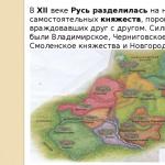 The value of the struggle of Russia with the Polovtsy
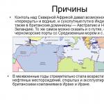 Asia and Africa after World War II