Three-phase voltage relay: diagram and connection features, price. What is a phase control relay and where is it used? Voltage relay 3 phase
Voltage relay necessary to protect the electrical network from voltage surges. Currently, the issue of a stable voltage in the electrical network is quite acute. Network organizations are in no hurry to reconstruct and modernize power lines, substations and transformers. Meanwhile, the situation is only getting worse, so voltage fluctuations in our networks are quite common.
For those who still doubt the installation of a relay for protection of their home or believes in the quality of construction and installation work in modern new buildings. Below is a screenshot of one of the latest

According to GOST 29322-92 voltage in the power grid of our country should be within 230 V at one phase and 400 V between phases. But if you live in a rural area or near a city, then problems with constant voltage levels are very high, and in the city itself this cannot be ruled out, especially in older housing stock. Voltage surges have a very detrimental effect on electrical appliances in the house. For example, due to low voltage, a refrigerator or air conditioner may burn out (the compressor will not start and overheat), the power of the microwave is greatly reduced, and incandescent lamps glow dimly. Well, high voltage will simply “kill” your household appliances. I'm sure many have heard about "zero burnout" in high-rise buildings, and how entire entrances are taken to workshops to repair household appliances.
The reasons for voltage fluctuations in the network are different:
- Shorting one of the phases to neutral, the result will be 380 Volts in the outlet.
- Burnout (break) of zero, if you have a low load at this time, then the voltage will also tend to 380 V.
- Uneven distribution of load across phases (misalignment), as a result, the voltage decreases at the most loaded phase, and if a refrigerator and air conditioners are connected to it, there is a high probability that they will “burn out.”
Example video showing the operation of a voltage relay
Special devices - voltage control relays - help solve the problem of voltage surges in networks. The principle of operation of such relays is quite simple, there is an “electronic unit” that monitors that the voltage is within the limits specified by the settings and, if there are deviations, signals the release (power section), which turns off the network. All household voltage control relays turn on automatically after a certain time. For ordinary consumers, a delay of a few seconds is sufficient, but for refrigerators and air conditioners with compressors a delay of several minutes is needed.
Voltage control relays are available in single-phase and three-phase types. Single-phase voltage relays disconnect one phase, while three-phase voltage relays disconnect all three phases at the same time. When using a three-phase connection at home, single-phase voltage relays should be used so that voltage fluctuations on one phase do not lead to the shutdown of other phases. Three-phase ones are used to protect motors and other three-phase consumers.
I divide surge protection devices into three types: UZM-51M from Meander, Zubr from Electronics and all the others. I am not imposing anything on anyone - this is my personal opinion.
Voltage relay Zubr (Rbuz)
This device is designed to protect against voltage surges (zero burnout). BISON is produced in Donetsk.

I will note the features of this voltage relay.
Voltage indication on the device - shows the voltage value in real time. This is quite convenient and necessary for assessing the voltage situation in the network. The reading error is low, the difference relative to the Fluke 87 high-precision multimeter is only 1-2 Volts.
Zubr voltage relays are produced for various rated currents: 25, 32, 40, 50 and 63A. The device, with a rated current of 63A, can withstand a current of 80A for 10 minutes.
The upper voltage value is set from 220 to 280 V in steps of 1 Volt, the lower - from 120 to 210 V. The restart time is from 3 to 600 seconds, in steps of 3 seconds.
I set the Zubr relay, the maximum (upper) voltage value is 250 Volts, and the lower value is 190 Volts.
For devices with index t in the name, for example Zubr D63 t, there is thermal protection against internal overheating. Those. when the temperature of the device itself increases to 80 degrees (for example, due to heating of the contacts), it turns off.
Zubr relays occupy 3 modules or 53 mm on a DIN rail and are only single-phase.
The passport and the Zubr connection diagrams provided do not say about current limitations, but in the old documentation it was previously indicated that no more than 0.75 of the nominal.
Zubr voltage relay wiring diagram
Currently, manufacturers claim that the relay can be connected at its nominal value. If the rating of the Bison is less than the rating of the input circuit breaker, then you need to use a voltage relay - a contactor - in the connection diagram.
Relay warranty Voltage Zubr the manufacturer gives whole 5 years! Has very good reviews from colleagues - forum members. And just like Meander on the MasterCity forum there is a Zubra representative who is not afraid to communicate publicly. And by the way, it is indicative from the example of UZM and Zubr that representatives of manufacturers of quality products are not afraid to communicate on forums.
Video about voltage relay Zubr
Update (06/07/15). Currently, the Zubr voltage relay is sold in Russia under a different name Rbuz (the word Zubr is backwards).
This is due to the fact that in Russia the Zubr trademark is registered with another manufacturer and only the name of the relay has changed, but all the components remain the same.
 .
.
UZM-51M. The protection device is multifunctional.
UZM-51M is designed for current up to 63A, occupies 2 modules on a DIN rail (35 mm wide). In the standard version, the operating temperature of the UZM is from -20 to +55 degrees, so I do not recommend installing it in a switchboard outdoors. It is true that there is a range from -40 to +55, but I have never seen such on sale, unless you contact Meander JSC directly.The maximum setting for the upper voltage cut-off is 290 V, the lower threshold is 100 V. The restart time is set independently - this is either 10 seconds or 6 minutes. Can be used in networks with any type of grounding: TN-C, TN-S, TT or TN-C-S.
Connection diagram UZM-51M


Meander produces two more types of single-phase voltage relays - these are UZM-50M and UZM-16. The main difference between the UZM-50M and the UZM-51M is, perhaps, only that in the latter, as we know, you can set the triggering setting yourself, while in the UZM-50M the setting is “hard”, the upper voltage limit is 265 V, and the lower - 170 V.
UZM-16 is designed for a current of 16A, so it is installed only on a separate electrical receiver. For example, in order not to wait 6 minutes for the UZM-51 to turn on, the refrigerator can be connected via the UZM-16, on which the turn-on delay is set to 6 minutes, and on the main UZM-51M to 10 seconds.
I set the maximum (upper) voltage value on the UZM-51M to 250 Volts, and the lower value to 180 Volts.
Meander also produces a three-phase voltage relay UZM-3-63, as I wrote above, such relays are used mainly to protect engines.

Good reliable surge protection. The UZM does not need to be connected with a contactor, as is usually done with other voltage relays. The device is manufactured in Russia. UZM warranty is 2 years. What’s important is that Meander’s representative is present on the most popular Mastercity forum, always gives advice on products, and also pays close attention to the comments of forum users, whose comments at one time helped improve the UZM-51M.
An example of installing UZM-51M in a three-phase switchboard for a country house, where UZM is installed in each phase.

Perhaps one drawback of the UZM-51M relative to other voltage relays is the lack of voltage indication. But the difference in price between the UZM and a voltage relay with a contactor allows you to buy and supply a voltmeter separately.
Voltage relay RN-111, RN-111M, RN-113 from Novatek
These voltage relays are manufactured here in Russia. As you can see from the title, Novatek offers three types of voltage relays.
RN-111 and RN-111M are practically the same device in terms of parameters; their main difference is that the RN-111M relay has a voltage indication, while RN-111 does not.
The upper voltage limit is from 230 to 280 V, the lower limit is from 160 to 220 V. The automatic restart time is from 5 to 900 seconds. These relays have a 3 year warranty.
Connection diagram for voltage relay RN-111

RN-111 is designed for small currents up to 16A or power up to 3.5 kW, but to connect a higher load, RN-111 can be switched on together with contactors (magnetic starters).
Connection diagram for voltage relay with contactor

This significantly increases the cost, since a good contactor will now cost about 4-5 thousand rubles, you will need a larger number of modules in the panel, as well as a circuit breaker to protect the contactor coil. The above diagram for connecting a relay with a contactor for RN-111 is valid for any other relay, taking into account the features of its circuit.
The RN-113 relay is already more improved relative to the RN-111, the voltage ranges and AR time are the same as those of the RN-111, but the maximum current for which the RN-113 can be turned on is up to 32A or if the power is up to 7 kW.
Connection diagram for voltage relay RN-113
But I would not do this, since the contacts on the RN-113 are weak enough for a wire with a cross-section of 6 mm 2, and this is precisely the cross-section required for a 32A connection.
It is more reliable to connect RN-113 with contactors, without contactors maximum 25A. I don’t use voltage relays from Novatek in my switchboards, so I borrowed the photo from one of the electricians from the Avs1753 forum.
It looks, of course, beautiful, but such a connection takes 3-4 more modules and is twice as expensive in cost as if UZM-51M or Zubr were used.
But what happens with the RN-113 if you connect it without 32A contactors.

Unfortunately, I did not find any information about tests like the UZM-51M and Zubr on the forums.
Relay DigiTop
Just like Zubr, these relays are produced in Donetsk. The manufacturer produces several series of devices with protection against power surges.
The V-protector series voltage relay is intended only for protection against voltage surges. Available for rated currents of 16, 20, 32, 40, 50, 63 A in a single-phase version, it has built-in thermal protection against overheating, triggered at 100 degrees. The upper threshold is from 210 to 270 V, the lower one is from 120 to 200 V. The automatic switching time is from 5 to 600 seconds. There is also a three-phase relay V-protector 380, quite compact 35 mm (two modules), but the maximum current in a phase is no more than 10A.
The Protektor single-phase voltage relay has a 5-year warranty, and the three-phase relay only 2 years.
V-Protektor DigiTop voltage relay connection diagram
Digitop also produces a voltage relay and a current relay, VA-protector, combined in one device. In addition to overvoltage protection, the device also provides current (power) limitation. Available for rated currents of 32, 40, 50 and 63 A. All voltage parameters are the same as those of the V-protector. Based on the rated and maximum current, VA controls the load and, if the rated current is exceeded, turns off the network after 10 minutes, and the maximum - after 0.04 seconds. The device display shows both voltage and current. VA-protector warranty is 2 years.


Well, the most advanced of the series of voltage relays from TM DigiTop is the MP-63 multifunctional relay. Actually, everything is the same as with the previous VA-protektor, only MP-63 shows, in addition to current and voltage, also active power.

This MP-63 relay and V-protector were independently tested by members of the forum, the reviews are average.
I tried to cover in my article the most common surge protection devices. Of course, there are still manufacturers of devices for this type of protection, but there is very little information about their use.
Thank you for your attention.
UZM-3-63 is a multifunctional device that provides control of 3-phase voltage in the network. It also has built-in varistor protection against surges and has the function of monitoring the frequency of the power supply from an autonomous generator.
The UZM-3-63 connection diagram is quite simple and its basic version can be found on the device body or in its passport. Here I provide a clear and more understandable connection diagram for a 3-phase voltage relay UZM-3-63 with circuit breakers, from which you can understand the essence of the connection.
All contacts of the device are marked on the housing. Therefore, without seeing the diagram itself, you can understand what is connected where. What is often confusing here is that the output phase contacts are marked U, V and W, which misleads many. How to connect this device?
Connects to the top contacts entrance:
- N - incoming zero working conductor;
- L1 - incoming conductor of phase A;
- L2 - incoming phase B conductor;
- L3 - incoming phase C conductor.
Connects to the bottom contacts exit:
- N - outgoing neutral working conductor;
- U - outgoing conductor of phase A;
- V - outgoing conductor of phase B;
- W - outgoing conductor of phase C.
Here is a photo of the UZM-3-63 device itself. The contacts of its polarized relay are designed for a long-term flow of a maximum current of 63A through them. If your load consumes more current, then this relay will no longer suit you or you will have to turn it on through a powerful contactor.
The options for completing the shields can be varied, but the essence of connecting the device always remains the same.

When using UZM-3-63, remember that when the load is disconnected, the neutral working conductor is not switched, i.e. doesn't break. Here only the phase conductors are broken.
The device settings are adjusted manually using three special switches. They set the high and low voltage limits and the restart delay time.
The relay light indication is intuitive. Next to all the indicators on the body there is their designation.
Someone, instead of a 3-phase UZM-3-63 relay, uses three single-phase UZM-51M. That is, one single-phase relay is installed on each phase. In principle, this option has the right to life, but it requires more space in the shield and costs almost twice as much.
Do you use a three-phase voltage relay UZM-3-63?
Let's smile:
As you know, the resistance of the human body is about 100 kOhm. Every 100 g of vodka taken internally reduces body resistance by 1 kOhm. How much vodka do you need to drink to achieve a state of superconductivity?
The phase voltage control relay allows you to instantly turn off the electricity after the meter in the event of an emergency - a power surge in the network. This device is used in both single-phase and three-phase electrical networks to protect electricity consumers from failure. Next, we will look at typical wiring diagrams for voltage relays in an apartment panel.
So, the simplest wiring diagram from the input circuit breaker in the apartment to the voltage control relay looks like this: 
In this case, the network is single-phase (220 Volts) and the load is no more than 7 kW, so there is no additional need to connect it to a DIN rail. If the load is more than 7 kW, it is recommended to connect via a starter, as shown in the second diagram for connecting the RN-113 relay: 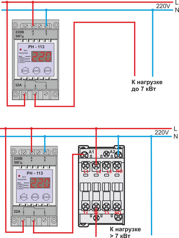
We immediately draw your attention to the fact that in addition to the distribution panel there must be an RCD or a circuit breaker in order to protect the residents of the house from leakage currents that can cause. The schematic diagram for connecting a voltage relay and an RCD (or a difavtomat) looks something like this: 
If you have a three-phase 380-volt network in your private home, the protective device can be connected according to one of two schemes: 

The first is recommended to be used if there are no three-phase consumers in the house - a powerful electric stove or 380 V boiler. If you use 3-phase electric motors, you need to protect them with an appropriate voltage relay, for example, RNPP-311 or RKN 3-14 -08, the diagrams of which we provide you with: 

Correctly connecting the device to the network
Using a cross module
As you can see, both options additionally have a magnetic starter, which allows you to switch high loads (over 7 kW). In addition, the starter allows you to remotely control the protection, which makes this voltage relay connection diagram very convenient!
To protect expensive household or electrical appliances from power surges, which could lead to their breakdown, a voltage control relay is used. This device provides the rated mains voltage. We’ll talk about the design and connection features of the voltage control relay below.
Design and principle of operation of a voltage control relay
The operating principle of a voltage control relay is to prevent overvoltage or undervoltage of the electrical network.

In answer to the question why you should install a voltage control relay, we will highlight several reasons:
- during an overhead line break in the private sector, a voltage surge of 160 W more than usual is possible, as a result of which some easily vulnerable electrical appliances easily burn out and require repair;
- in bad weather or for other reasons, a break in the neutral wire leads to increased load and damage to electrical equipment;
- when the house is located far from the transformer, the voltage drops to a critically low level, this also negatively affects the operation of electrical equipment;
- When a powerful consumer of electricity is turned on, the phase is overloaded, and as a result, due to a lack of voltage, equipment may break down.
The relay consists of a microcircuit that controls its operation. The microcircuit detects a decrease or increase in voltage, transmits a signal to an electromagnetic relay, and the device is instantly turned on, which equalizes the voltage.
The operating range of the voltage control relay is from 100 to 400 W. During a thunderstorm, lightning discharges exceed these indicators, so it is not recommended to rely on a voltage control relay and turn on electrical appliances in bad weather. For such purposes, there are voltage limiters.
The voltage control relay consists of two parts:
- electronic,
- power.
The first part controls the voltage, and the second part performs load distribution actions.
The main part of the relay is the microprocessor or compactor. A microprocessor based relay is the best as it can smoothly regulate voltage changes.
The main property of voltage control relays is fast action and response. The response threshold depends on the potentiometer setting.
Voltage control relays differ from stabilizers in their operating principle. During voltage surges, the relay turns off those areas where the voltage does not reach normal. Stabilizers - regulate and distribute voltage evenly throughout the network.
Therefore, during emergency situations, it is more effective to use a voltage control relay, which will turn off emergency areas.

Scope of use and advantages of voltage monitoring relays
To avoid overloading of electrical appliances, such as a refrigerator, boiler, boiler, during a decrease or increase in voltage in the electrical network, a voltage control relay is used.
The voltage control relay has a wide range of uses, since electrical appliances are present almost everywhere, then a voltage control relay is necessary in any establishment.
Scope of use of voltage monitoring relays:
- protection of single-phase or three-phase networks;
- protection against breakage, sticking, phase imbalance;
- prevention of violation of sequential operation of phases;
- protection of electrical equipment from breakdowns;
- use in the protection of devices that have long-term transient operation;
- when using devices with a load on an electric motor;
- special installations requiring high-quality voltage and the presence of full phases;
- used to protect household and electrical appliances from overvoltage in residential buildings and apartments;
- used in public institutions: schools, supermarkets, electronics stores, computer rooms, hospitals, cinemas, to protect expensive equipment from damage;
- in industrial establishments in factories and factories, to prevent equipment failure.

Advantages of using a voltage monitoring relay:
- high operating temperature range from -20 to +40, allows the devices to be used both outdoors and indoors;
- the variety of types of these devices allows you to choose a voltage control relay in relation to material preferences;
- voltage control relay provides reliable protection of expensive equipment from over- or under-voltage and prevents its breakdown;
- a wide selection of models and manufacturers of voltage control relays opens up many opportunities for the buyer to satisfy individual requests;
- ease of installation allows you to install this device yourself, without the help of an electrician;
- modern models are distinguished by the presence of an original design that easily fits into the overall interior of the room;
- during power surges there is no increase or decrease in light intensity;
- The device automatically turns off sections of the electrical network that are damaged in the event of an accident or bad weather.

Types of phase and voltage control relays
Depending on the type of connection, relays are distinguished:
- fork-socket shape;
- in the form of an extension;
- rail mounted.
1. The first type of voltage relay is distinguished by the presence of a plug, which facilitates its installation. Such a device simply needs to be plugged into an outlet. It only protects certain groups of consumers. The device is controlled by a microcontroller. It analyzes the current supply voltage and then displays this value on a digital screen. An electromagnetic relay regulates and turns off the load. Such devices have buttons that allow you to turn off and adjust the voltage limits.
2. The voltage control extension relay is similar to the previous type of device. They differ in that the relay extension cord has several sockets and allows simultaneous protection of two or more devices.
3. The relay installed on the D I N rail is mounted directly into the distribution cabinet. Such devices allow you to provide voltage protection for the entire house or apartment. They are distinguished by the presence of additional functions and settings and operate in several modes.
In relation to the type of load, voltage control relays are distinguished:
- single-phase,
- three-phase.

To protect three-phase motors and equipment, devices of the first type are used. They are designed to protect air conditioners, refrigerators, compressors, and other electrically driven devices.
In a room that provides full-phase control, it is also recommended to use three-phase control relays. If there is a three-phase input in the room, it is possible to install a three-phase voltage control relay, but if one of the phases fails, the remaining two will also be turned off. Even with the slightest surges or phase imbalances, the relay will operate instantly. For example, if the voltage on one phase is 220 W, and on the second 210 W, all phases will be instantly de-energized. Although this voltage is absolutely normal and will not harm most electrical appliances.
Therefore, if there are three phases at the input, it is better to install separate single-phase relays for each individual phase. When choosing the power of a single-phase voltage control relay, it should be taken into account that the device indicates the power that it passes through itself, but does not open. Therefore, you should choose a single-phase control relay several tens of amperes higher than the power of the electrical network.

1. To buy a voltage control relay, contact a specialized store, which will provide a guarantee and advice on the safe use of this device.
2. Voltage control relay price depends on the following factors:
- type of device: socket - the cheapest, extension - average cost, rack - rack - more expensive;
- manufacturer: domestic relays are cheaper because they do not require payment for transportation, unlike foreign ones;
- additional functions - the ability to manually or automatically adjust the power limit of the device;
- design - some models have an attractive appearance, are characterized by the presence of several colors, and are, accordingly, more expensive.
3. When choosing a single-phase relay, you should correctly calculate the power of the device. Household relays are characterized by the presence of power contacts whose power does not exceed 100 A. It is recommended to increase the size of the required relay power by 25%, and then, based on the result obtained, select a single-phase type device. For example, if the power of the rated device is 20 A, then the power of the relay required to ensure normal operation of the electrical network will be 35, 30 A.
4. Three-phase relays are easier to choose, since they are all produced with a power of 16 A.
5. When purchasing a relay, be sure to read the operating instructions and ask for a warranty card for the product. Pay attention to the technical characteristics of the device, the material from which the body is made, the maximum and minimum operating temperature.
6. Before installing the relay, you should install an automatic shutdown device that can turn off the power supply if the voltage is higher or lower than the permissible norm.

7. Choose a device with a display that will constantly display the voltage value.
8. When choosing socket voltage control relays, install them on all expensive devices that are equipped with an electric motor.
9. The body material must be non-flammable, the most acceptable option is polycarbonate.
10. Please note that there is a function to control the device’s response time.
11. Additional protection of the device from overheating, measuring the exact value of the power of the electrical network - will allow the voltage control relay to work more efficiently.
Voltage control relay: connection and installation
Before you familiarize yourself with the rules for installing a voltage control relay, let's consider the reasons why you should install this device.
If the power of the electrical network is reduced, for example, if the constant power value in the house is 160-190 W, then a refrigerator, the service life of which is about ten years, will work under such conditions for a maximum of three years. Installing a voltage control relay will not help, since this device will constantly turn off the power supply, and the refrigerator will periodically defrost. In this situation, it is necessary to install a stabilizer. But, if power surges and breaks constantly occur in the electrical network, then installing a voltage control relay is quite appropriate.
To connect the relay you will need:
- voltage monitoring relay device,
- a small wire with a cross-section of 0.4-0.6 cm,
- iron rail for attaching the machine gun,
- self-tapping screws,
- pliers,
- indicator,
- screwdrivers.

Before installing the voltage control relay, turn off the power supply. To do this, turn off the input circuit breakers. Install a rail near the location of the machines and secure it to the wall using a screwdriver and self-tapping screws. The relay is fixed to the rail using a special design of latches, which are located at the back.
On the input machine, using the indicator, find the phase (the indicator should light).
Where the phase wire enters the room, it should be cut. One end of the wire should be connected to the relay, to the input contact, and the other end is connected to the output contact.
Turn on the power supply and check the operation of the device.
The socket type voltage control relay circuit is the simplest. After purchase, such a device is simply plugged into an outlet, and the plug of a certain device is already installed in it.

A mandatory element of voltage relay protection is the installation of an input circuit breaker. It is mounted near the machine and the relay itself. The rating of this device is one step less than the relay rating.
When installing a relay whose power exceeds 65 A, an additional starter must be used. To avoid frequent triggering.
This article is a continuation of the article about the device and circuit of the Barrier voltage relay. I described in detail how this wonderful device works, and now I will give an example of its use.
The background is briefly as follows.
My long-time clients approached me - a company that is engaged in vigorous activity on the Internet and advertising business. After their zero burned out, which I already wrote about in the article, they decided not to tempt fate further, but to protect themselves from voltage troubles.
Here is a terrible photo taken from that article:
Burnout of zero from the zero bus. The damage amounted to more than 100 thousand rubles.
This is what I wrote to the client in response to the request:
Technical proposal for modernization of the power supply system
Subscribe! It will be interesting.
To avoid damage to electrical equipment, it is proposed to install an additional circuit based on a voltage relay.
If the voltage goes beyond the permissible limits for various reasons (short circuit on the line, zero break, overload, etc.), the voltage relay will turn off the consumer.
As soon as the voltage returns to nominal, the voltage relay automatically turns on the power.
There are two options:
Option 1
Three-phase voltage relay. Turns off power to all consumers in case of problems in one of the three phases. A power contactor is required.
Option 2
Three independent single-phase voltage relays. In case of problems, it turns off only “its” phase. In this case, power is supplied to consumers of other phases (which are normal) as usual. No power contactor required.
Since all consumers are single-phase, Option 2 is preferable.
Approximate cost breakdown for two options:
Option two with three single-phase relays was chosen, since almost the entire load is single-phase. The exception is the three-phase ventilation panel, which powers a three-phase asynchronous motor. But it was decided not to allow this load through the Barriers.
Device diagram
Here is a diagram of a three-phase voltage control relay assembled on three single-phase Barrier voltage relays:

I emphasize once again that such a scheme is only suitable in cases where three-phase power is supplied to a switchboard from which a single-phase load distributed among the phases is supplied. When the load is three-phase (for example, electric motors), then the use of such a circuit can be dangerous, and option 1 (three-phase relay) must be used. Or change this circuit so that all three phases are turned off at once. To do this, it needs to be supplemented with a contactor, if anyone needs it, I’ll tell you in more detail.
For those who have read my previous articles, there is nothing incomprehensible in this scheme.
However, let me explain.
What's new in the VK group? SamElectric.ru ?
Subscribe and read the article further:
As usual, voltage is supplied to the meter through the input switch.
Each relay (A1, A2, A3) operates on its own phase (L1, L2, L3). The relay outputs are the outputs of this circuit; I decided to designate them as R, S, T. Next, the phases arrive normally at their single-pole circuit breakers, and through them they disperse to consumers.
Circuit breakers F1, F2, F3 are not protective and are used simply as bypass switches. They are supposed to always be off, otherwise this whole circuit makes no sense. They turn on as a bypass only in emergency cases when the voltage relay does not work for some reason.
And there can be two reasons for this - relay failure and voltage going beyond the established limits.
However, there is a third reason, which is not mentioned in the instructions, and which I talked about in the previous article - when the voltage limits change, the relay turns off. Therefore, the bypass machine must be turned on when setting up the voltage relay, otherwise the load will be turned off during the setup time.
Entry 1
The customer has 4 inputs for two buildings, they all have differences, I will draw the attention of readers throughout the article.
First input. In the electrical room I saw this picture:

1 – electrical panel
At the top left is a panel with an input switch, a three-pole D80 circuit breaker.
More details about the inside of the shield:

1 – electrical panel interior
Above – Three-phase meter Energomera, digital voltmeter Digitop VM-3, street-generator switch.
Read my article about the different ways to connect a generator. It tells you how to make manual and automatic transfer of reserve (ATR).
Here's a closer look at the first row, it will be very important for us, since all the connections will take place there:

1 – Counter outputs to switch
On the switch, at the top left, there are wires (white, blue, brown), into the gap of which we will need to connect our protection relay circuit. This place is even closer:

1 – Counter-generator switch
The flexible wires on the right side of the switch are from the generator, which is installed on the roof of the building.
Despite the fact that this electrical panel was assembled by a reputable company, immediately there is a serious mistake– pay attention to 25 Ampere machines:

1 – Gross mistake in choosing circuit breakers
And if on the right side of the photo a wire with a cross-section of 2.5 mm² can be understood and forgiven, then six wires of 1.5 mm² will no longer fit into any gate. Here I would lower the rating to 13 or 10A, but I need to deal with the load, and that’s not what I came to this facility for. For those interested, I discuss this problem in detail in an article about. There are also many links to relevant articles.
Okay, let's start assembling our circuit, which I put in a separate panel:

The wire for installation was PV1, single-core, with a cross-section of 4 mm². Or rather, VVG4x4 dissolved into sinews. I connected it into the gap through a terminal connection with a screw, I couldn’t take a photo, there will be more examples below.
Here's what we ended up with:

1 – Final view of the three-phase voltage control relay
I printed operating and setup instructions for users on the back of the cover. I will give the text below.
Input 2
Here I photographed the input machine:

2 – Input automatic switch (switch) to the meter
Three-phase input differs fundamentally from single-phase. More details -.
And the electrical panel looked like this:

2 – appearance of the electrical panel
The meter has a magnetic seal. Why it is needed - I refer you to the article about. But I say again - you need to live honestly!

2 – Magnetic seal on a three-phase meter
Appearance of the place where there will be a gap for connecting our voltage control relays:

2 – counter outputs
Closer, we are interested in the upper connection to the switch, on the left:

2 – wires between the meter and the switch, where the three-phase voltage relay will be connected
There's still a voltmeter in the way, but you'll have to leave it.
The process of assembling the second panel with three Barrier voltage control relays is shown:

2 – Three-phase voltage control relay based on Barrier relay
This is how this shield is connected:

2 – Connecting the voltage relay to the gap after the meter
This connection is very important because all power to the office goes through it. Therefore, I made it through screw-type terminal blocks (clamps).
The blue wires that previously went to the switch terminals now go through the terminals to the voltage relay panel. And from the Barrier outputs, the wires are connected directly to the switch terminals.
The connections in the panel are shown in the photo:

2 – Connections in the panel of the three-phase voltage control relay
The input cable carries three phases and zero. The current through the neutral wire is more than 100 times less than through the phase wires, so it can be neglected.
The second output cable uses three cores, the fourth is a spare (reserve).
As a result, the currents in the cables are the same, the cable is used at 75%, which is optimal from the point of view of overheating.
The second electrical panel took this form:

2 – Electrical control room with a new panel
A closer look at our shield:

2 – Panel with three-phase voltage control relay
Entry 3
Below are photos of the assembly and installation of the shield on the third input.

3 – assembly process.
Pay attention to the color sequence of the wires. Question: Which country am I a patriot?
I decided to use a flexible PVS 4x4 cable, because I had suffered in the first previous cases with solid cores. But in this case it is necessary to use tips, because... for screw terminals, which are used in Barriers, the strand is not comme il faut.

3 – Electrical panel assembled and installed
In the previous two versions, the wires went from top to bottom under the DIN rail, which is a little annoying.
Therefore, here I expanded the consciousness and the distance between the phases, and laid wires into the resulting gaps. The fact is that the Barrier block occupies approximately 2.8 modules on the DIN rail, and there will be gaps in any way. So why not use them for convenient installation?

3 – Shield with Barriers installed

3 – General view

Input 4

4 – Appearance of the shield. A three-phase Barrier is connected to the gap through the screw terminal block
Closer. I think everyone understands why I use a terminal strip and do not connect directly to the meter terminals?

4 – Counter output – to terminal block
In previous versions, the panels were external, installed in electrical panels (utility rooms) and there were no installation problems. Immediately I had to make a built-in installation; I needed a drywall hacksaw.

4 – Inserting the shield into a plasterboard wall

4 – Final look
User instructions
As promised, I am posting instructions for the voltage relay, which can be seen in the photo.
I tried to write in simple language what it is, why and how:
Voltage control relay
Designed to automatically switch off the load if the voltage value exceeds the permissible limits. They work on each phase separately.
Automatic machines F1, F2, F3 – bypasses, during normal operation MUST BE TURNED OFF(lower position). They are switched on in emergency cases, under the personal responsibility of the switcher!
Attention! When the bypass is turned on, the load is not protected from dangerous voltages!
During normal operation, voltage relays A1, A2, A3 indicate the voltage value in their phase.
If the voltage goes beyond the set limits, the relays are turned off and the voltage readings flash.
Turning on - approximately 1 minute after the input voltage has normalized.If you need to change the voltage limits, please refer to the instructions. While setting voltage limits and delay time the bypass circuit breaker must be turned on.
Thank you all for your attention, questions and comments, as always, I’m waiting for you in the comments.


