Kharchenko antenna: calculation and manufacturing. Building a Biquad antenna Improving UHF reception
We previously touched upon the designs of directional Wi-Fi antennas. Bi-square, canned homemade rarities. People are constantly looking for a chance to get a better design. It was mentioned: instead of traditional wire, it is better to use PV1 wire of a similar cross-section, which protects the installed antenna from bad weather. A board with double-sided foil, which is often recommended to be used as a reflector, does not withstand bad weather very well, is not protected by anything, and it is problematic to equip the design with a special housing. The wind load on the product will increase. Today's review is dedicated to methods for improving the design. DIY Wi-Fi antenna for any weather!
Important! Try using shrink wrap for protection. Put a “fur coat” on the reflector and blow it with a hairdryer. Soon the PCB will be tightly covered with a polymer film.
Biquad Wi-Fi Antennas
The Wi-Fi antenna, built according to a biquad pattern, is formed by a grounded reflector, a figure-of-eight emitter with right (90 degrees) angles. The result is something reminiscent of trendy glasses with a thin bridge in the middle. The lower half is planted on the ground, the upper half - on the signal core of the RK-50 cable.
True, the antenna for Wi-Fi will be smaller in size. The side of the square along the midline of the copper core of the emitter is 30.5 mm. So, the figure eight is 1.5 (half the length of the side of the square) cm from the reflector and is parallel to the plate. In our case, the getinax board is bad because it is difficult to get. A reflector is simply a plate of electrically conductive metal. Tin, steel, aluminum will do. Considering the size of the emitter, you can make a Wi-Fi antenna reflector using a 5.25-inch laser compact disc (DVD).
Biquadrat Kharchenko
The internal reflective layer of aluminum is designed to prevent the laser beam from losing energy on the surface. In addition, there is a hole in the center for an N-connector. All that remains is to open the protective plastic shell and place the reflective layer on the screen of the RK-50 cable. Please note: if the N-connector and the emitter are not 1.5 cm from the reflector, the reception conditions will worsen. It is necessary to achieve the specified position by placing thin metal washers or in place.
We remind you: the bi-square figure eight bends from the middle by turning 90 degrees. Both ends of the PV1 1x2.5 cable will return to the point. The thickness of the wire is 1.6 mm in diameter, the side of the square between the centers of the core is 30.5 mm. The ends are placed on the connector screen, combined with a reflector (CD), the middle part will serve the purpose of picking up the signal. The radiation pattern of the device narrows sharply and is equipped with one main lobe, which is directed towards the signal source. If this happens in a room, you will have to experimentally find a reflected beam located in almost any direction.
The reflector will protect from neighboring interference and increase power. Blocks the multipath effect, which brings little benefit to the equipment. A homemade Wi-Fi antenna receives only from a narrow sector. Thanks to this, we will connect the houses opposite with a network, which would be impossible with the access point supplied in the kit.
Please note: in other cases there may not be an input connector on the case for connecting an antenna. Such access points are equipped with built-in metal circuits that receive radio waves. Traditionally they look like intricate flat figures on the inside of the case. You'll have to unsolder the built-in antenna.
There may be a capacitor nearby; the capacitance serves to compensate for the compression ratio of the circuit. The built-in antenna is small and powerless to form a full-fledged device for receiving radio waves. The defect is neutralized by a tuning capacitor.
The element is not needed, because a full-size antenna for a Wi-Fi router does not need compensation. Break the homemade switching circuits above the capacitor. When performing installation, you cannot use a typical 100 W soldering iron. It will burn the electronic components of the board. You will need a small soldering iron equipped with a 25 W tip.
The weight of the compact disk is small, the wind load is low, in contrast to the bulky design, and it will not kill anyone from below with a falling getinax board. It is recommended to avoid placing products in the sun, but in our case the recorded information does not play a great role. If desired, seal the N-connector to extend the life of the solder joint. A special gel compound is used, used when installing printed circuit boards. Similar ones are produced by the Allure company (St. Petersburg). A few words will explain how to make a Wi-Fi antenna with your own hands more powerful.
Biquad Wi-Fi antennas are not the limit, we’ll run away from our neighbors
Prologue: 2 weeks, I couldn’t find the reason, then I turned the antennas vertical and got 20 Mbit per 5 km, instead of horizontal 4.
Vampirenysh, member of the Ukrainian Local Networks forum (spelling copied).

Before you buy a Wi-Fi antenna, think: theory shows that emitters located in rows narrow the radiation pattern in a direction perpendicular to the line along which the elements are lined up. Translated into Russian it means: if our houses and a friend’s are separated by 100 meters, the width of the antenna’s viewing sector for implementing a Wi-Fi communication channel barely exceeds 15 degrees. The useful power will be directed to the friend's window (it will only cause harm to the inhabitants of the apartment!). To implement the circuit, use a dual biquad antenna. You can increase the speed if you give the same one to a friend as a gift!
How to make a Wi-Fi antenna so that it doesn’t interfere with your neighbors. You can protect yourself from uninvited guests by changing the channel and polarization. Three methods have been found to protect the channel by antenna configuration:
- Frequency selection.
- Choice of direction (narrowing of the radiation pattern).
- Choice of polarization.
Usually, when there is Wi-Fi provided by the provider, the values are set by the communication provider, the client has to obey, but if he has his own equipment, the situation is different. We can install the antenna on vertical polarization if our neighbors use horizontal polarization. Our equipment will no longer see each other. This can be done unilaterally or by agreement. You will need antennas like biquad antennas, leave the supplied ones aside.
Television operates on horizontal polarization, and communications operate on vertical polarization. It’s just a tradition, it’s convenient to hold the radio pin perpendicular to the ground when you talk. In this context, it is advantageous to use vertical polarization, which is usually found in routers. We offer a simple rule:
- Position the antenna opposite the windows with a friend in the same way. Spatial compatibility is ensured, which is a subtype of electromagnetic compatibility. Microwaves, telephones, and a mountain of 2.4 GHz equipment were released, causing interference. Position the antennas equally, vertically, horizontally, tilted. Experimentally look for the position at which the speed is greatest.
The promised new product: a design of four squares lined up in a row. The radiation pattern will become narrow in the direction perpendicular to the formation. Copper wire or single-core wire with a cross-section of 2.5 mm 2 and a length of 50 cm. We recommend taking it with a reserve. If a standard biquad Wi-Fi antenna for a laptop is an in-phase array of two frames, in our case there are four frames.
Frame for dual biquad antenna
When the wave moves, the current in neighboring squares is directed oppositely along the contour. Due to this, the effect of the field is added up. Now we need to get four in-phase squares. Find the middle of the wire and make a 90 degree bend. We measure 30 mm, make bends on each side in the opposite direction. We retreat twice as much, again pressing in the first direction. You will get a large letter W. Another 30 mm - bend the edges downwards at 90 degrees. One half is ready.
We make the second one in the same way so that the ends return to the point of the initial bend. Please note that it is not in vain that we recommend using a wire with a polyvinyl chloride sheath - the two crosshairs in the figure are mutually isolated.
We cut off the excess wire so that the ends do not reach two to three millimeters before the first bend. A Wi-Fi antenna for a computer requires a reflector; a good piece of foil PCB or standard flat sheet metal will do. We use an N-connector for connection.
The emitter is separated from the reflector by 1.5 cm in area. We place the ends on the ground, the middle - on the signal core (cable for Wi-Fi antenna RK - 50). To strengthen the edges of the figure, use ceramic or plastic tube. For fixation and electrical insulation, use glue or sealant. For the outdoor version, it is recommended to find a plastic case. Keep the distance between the homemade antenna and the receiver smaller.
The next meeting will discuss the Wi-Fi radio.
If you want to assemble a long-range WiFi antenna, then you should know about some of its features.
The first and simplest: large antennas of 15 or 20 dBi (isotropic decibels) are the maximum power, and there is no need to make them even more powerful.
Here is a clear illustration of how, as the antenna power in dBi increases, its coverage area decreases.
It turns out that as the antenna’s operating distance increases, its coverage area decreases significantly. At home, you will have to constantly catch a narrow band of signal coverage if the WiFi emitter is too powerful. Get up from the couch or lie down on the floor, and the connection will immediately disappear.
That's why home routers have conventional 2 dBi antennas that radiate in all directions - so they are most effective over short distances.
Directed
9 dBi antennas only work in a given direction (directional) - they are useless in a room, they are better used for long-distance communications, in the yard, in the garage next to the house. The directional antenna will need to be adjusted during installation to transmit a clear signal in the desired direction.
Now to the question of carrier frequency. Which antenna will work better at long range, 2.4 or 5 GHz?
Now there are new routers operating at double the frequency of 5 GHz. These routers are still new and are good for high-speed data transfer. But the 5 GHz signal is not very good for long distances, as it fades faster than 2.4 GHz.
Therefore, old 2.4 GHz routers will work better in long-range mode than new high-speed 5 GHz ones.
Drawing of a double homemade biquadrat
The first examples of homemade WiFi signal distributors appeared back in 2005.
The best of them are the biquadrate designs, which provide a gain of up to 11–12 dBi, and the double biquadrate, which has a slightly better result of 14 dBi.
According to usage experience, the biquadrate design is more suitable as a multifunctional emitter. Indeed, the advantage of this antenna is that with the inevitable compression of the radiation field, the signal opening angle remains wide enough to cover the entire area of the apartment when installed correctly.
All possible versions of a biquad antenna are easy to implement. 
Required Parts
- Metal reflector - a piece of foil-textolite 123x123 mm, a sheet of foil, a CD, a DVD CD, an aluminum lid from a tea can.
- Copper wire with a cross section of 2.5 mm2.
- A piece of coaxial cable, preferably with a characteristic impedance of 50 Ohms.
- Plastic tubes - can be cut from a ballpoint pen, felt-tip pen, marker.
- A little hot glue.
- N-type connector - useful for conveniently connecting an antenna.
For the 2.4 GHz frequency at which the transmitter is planned to be used, the ideal biquadrate size would be 30.5 mm. But still, we are not making a satellite dish, so some deviations in the size of the active element - 30–31 mm - are acceptable.
The issue of wire thickness also needs to be considered carefully. Taking into account the selected frequency of 2.4 GHz, a copper core must be found with a thickness of exactly 1.8 mm (section 2.5 mm2).
From the edge of the wire we measure a distance of 29 mm to the bend.
We make the next bend, checking the outer size of 30–31 mm.
We make the next inward bends at a distance of 29 mm.
We check the most important parameter of the finished biquadrat -31 mm along the center line.
We solder the places for future fastening of the coaxial cable leads.
Reflector
The main task of the iron screen behind the emitter is to reflect electromagnetic waves. Correctly reflected waves will superimpose their amplitudes on the vibrations just released by the active element. The resulting amplifying interference will make it possible to propagate electromagnetic waves as far as possible from the antenna.
To achieve useful interference, the emitter must be positioned at a distance that is a multiple of a quarter of the wavelength from the reflector.
Distance from emitter to reflector for biquad and double biquad antennas we find lambda / 10 - determined by the features of this design / 4.
Lambda is a wavelength equal to the speed of light in m/s divided by the frequency in Hz.
Wavelength at a frequency of 2.4 GHz is 0.125 m.
Increasing the calculated value five times, we get optimal distance - 15.625 mm.
Reflector size affects the antenna gain in dBi. The optimal screen size for a biquad is 123x123 mm or more, only in this case can a gain of 12 dBi be achieved.
The sizes of CDs and DVDs are clearly not enough for complete reflection, so biquad antennas built on them have a gain of only 8 dBi.
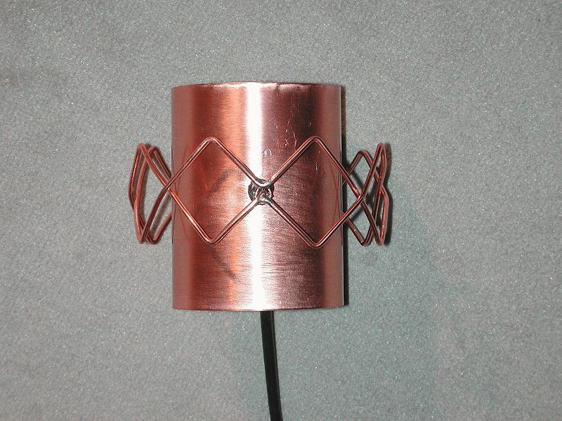
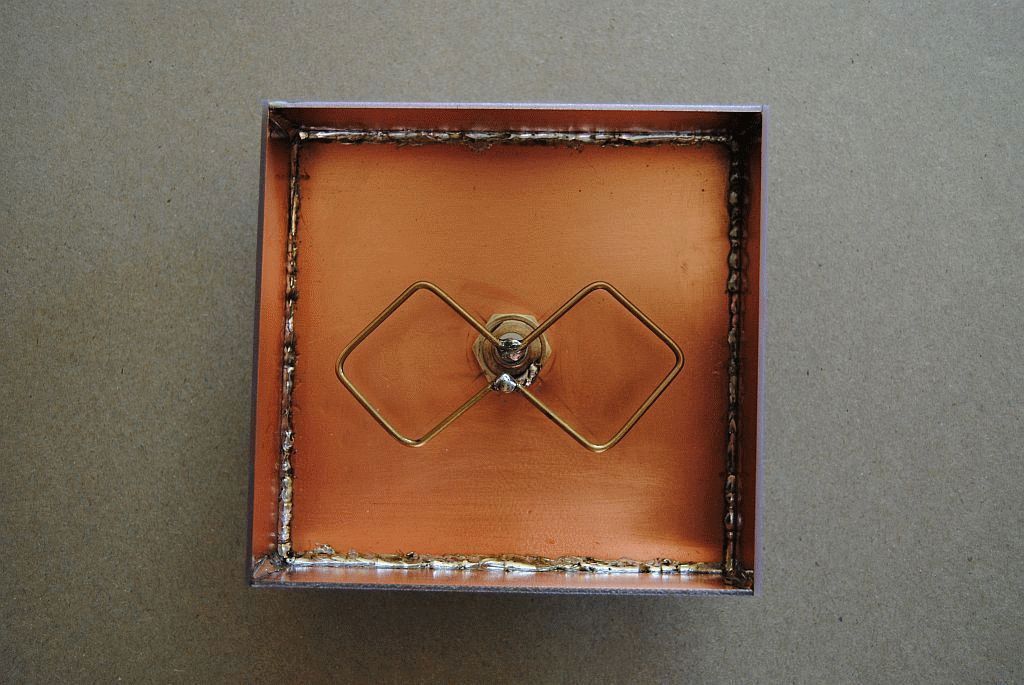
Below is an example of using a tea jar lid as a reflector. The size of such a screen is also not enough, the antenna gain is less than expected.
Reflector shape should only be flat. Also try to find plates that are as smooth as possible. Bends and scratches on the screen lead to the dispersion of high-frequency waves due to disruption of reflection in a given direction.
In the example discussed above, the sides on the lid are clearly unnecessary - they reduce the signal opening angle and create scattered interference.
Once the reflector plate is ready, you have two ways to assemble the emitter on it.
- Install the copper tube using soldering.
To fix the double biquadrat, it was necessary to additionally make two stands from a ballpoint pen.
- Secure everything to the plastic tube using hot glue.
We take a plastic box for discs for 25 pieces.
Cut off the central pin, leaving a height of 18 mm.
Use a file or file to cut four slots in the plastic pin.
We align the slots to the same depth
We install the homemade frame on the spindle, check that its edges are at the same height from the bottom of the box - about 16 mm.
Solder the cable leads to the emitter frame.
Taking a glue gun, we attach the CD to the bottom of the plastic box.
We continue to work with a glue gun and fix the emitter frame on the spindle.
We fix the cable on the back of the box with hot glue.
Connecting to a router
Those who have experience can easily solder to the contact pads on the circuit board inside the router.
Otherwise, be careful, thin traces may come off the printed circuit board when heated for a long time with a soldering iron.
You can connect to an already soldered piece of cable from a native antenna via an SMA connector. You shouldn't have any problems purchasing any other N-type RF connector from your local electronics store.
Antenna tests
Tests have shown that an ideal biquad gives a gain of about 11–12 dBi, and this is up to 4 km of directional signal.
The CD antenna gives 8 dBi, since it can pick up a WiFi signal at a distance of 2 km.
Double biquadrate provides 14 dBi - slightly more than 6 km.
The opening angle of antennas with a square emitter is about 60 degrees, which is quite enough for the yard of a private house.
About the range of Wi-Fi antennas
From a native router antenna of 2 dBi, a 2.4 GHz signal of the 802.11n standard can spread over 400 meters within line of sight. Signals of 2.4 GHz, old standards 802.11b, 802.11g, travel worse, having half the range compared to 802.11n.
Considering a WiFi antenna to be an isotropic emitter - an ideal source that distributes electromagnetic energy evenly in all directions, you can be guided by the logarithmic formula for converting dBi to power gain.
Isotropic decibel (dBi) is the antenna gain, determined as the ratio of the amplified electromagnetic signal to its original value multiplied by ten.
AdBi = 10lg(A1/A0)
Conversion of dBi antennas into power gain.
| A,dBi | 30 | 20 | 18 | 16 | 15 | 14 | 13 | 12 | 10 | 9 | 6 | 5 | 3 | 2 | 1 |
| A1/A0 | 1000 | 100 | ≈64 | ≈40 | ≈32 | ≈25 | ≈20 | ≈16 | 10 | ≈8 | ≈4 | ≈3.2 | ≈2 | ≈1.6 | ≈1.26 |
Judging by the table, it is easy to conclude that a directional WiFi transmitter with a maximum permissible power of 20 dBi can distribute a signal over a distance of 25 km in the absence of obstacles.
The well-known and very popular wifi antenna Biquad or Zigzag Kharchenko, as well as the Trevor Marshall antenna, have excellent characteristics and ease of assembly. There are many modifications of such a wifi antenna, but I suggest sticking with a regular biquad antenna as it has an excellent ratio of work + materials / gain.
To start making the antenna, we need to prepare the materials:
We cut out a reflector measuring 110 x 110 mm from PCB and drill a hole in the center equal to the outer diameter of the copper tube. The tube should be selected so that the existing cable fits tightly into it with an evenly laid outer braid and a length of 5 cm.
We tin the hole and prepare the tube; depending on the diameter of the wire + 0.5 mm, we grind off half the radius of the upper part.

We insert the tube into the PCB so that the top of the tube is 16mm above the reflector. I think there is no need to say that everything is done carefully and as accurately as possible. Now let's bend the second part of the antenna from the wire. Let's prepare a wire 244 mm long and make notches every 30.5 mm. Now all that remains is to bend the wire according to the pictures below.


It remains to connect the two parts of the wifi antenna. We solder the free ends of the wire to the highest point of the tube, and in the section there remains a whole part to which the central core of the RG-6U cable is soldered.

Insert the cable and solder it.


Biquad assembled.
You can do without a tube by using a special N-type connector, this is everyone’s business.

In conclusion, I will say that this antenna is an excellent replacement for the “can”. The gain of this antenna is around 6-8dbi. Due to its small dimensions, it can be used as a parabolic mirror feed, which will give a minimum of 19 dB of gain.
With DVB-T2 support, naturally he needed an antenna, which of course he had to make himself. We will talk further about how to make an antenna for DVB-T2 with your own hands.
To begin with, I decided to test the Kharchenko biquadrat antenna, or “eight” in common parlance. For manufacturing we need copper or aluminum wire with a diameter of 2-5 mm. I had a 2.5 square VVG on hand and I decided to try to make an antenna for DVB-T2 from it.
Antenna calculation
Let's find out our frequencies of both DVB-T2 packages in our area. To do this you can go to the website of the CETV Interactive Map and see which tower is closer to you, one or both channel packages broadcast and at what frequencies. In our suburbs of St. Petersburg, these are 586 MHz and 666 MHz.
Now knowing the packet frequencies, we need to calculate the length of the square side of our DVB-T2 antenna. It is equal to a quarter of the wavelength.
That is, for our 586 MHz: 300000000/586000000=0,51 meter. Quarter wavelength respectively 0,51/4=0,127 meters or 12,7 cm.
For the second multiplex 666 MHz we calculate similarly and get 11,2 cm.
We are interested in L1. H and B for antenna with reflector (array), amplifies the signal. I did it without him.
Now, if we make an antenna for two packages of DVB-T2 channels, we determine the average length. That is, we add up our lengths and divide in half.
L1=(12.7+11.2)/2=11.95 round up to 12 cm.
Antenna assembly for DVB-T2
Everything should be clear here. We take our segment VVG or whatever you have. To determine the approximate length of wire required to assemble the antenna, you can L1 * 8 and throw a couple of centimeters. 12*8+2=98 cm was needed to make my antenna.
If you have thick wire 4-5 mm in diameter, then most likely you will not be able to do without a vice. I had enough pliers.
We strip the wire from insulation. Then use pliers to bend the biquadrat. Let's look at the photos. All angles are 90 degrees.

Then we solder the 75 Ohm television cable. We solder the core to one square, the braid to another.

The signal at high frequencies propagates over the surface of the conductor, so it is better to paint the antenna after assembly. I used leftover acrylic exterior paint. It is better to fill the soldering area with hot glue or sealant.
We secure the wire from the soldering point with ties (straps) along the sides of the square, as in the photo. This mandatory action is antenna matching.
Testing a homemade antenna on a homemade TV
So a biquadrate gives a signal amplification of about 6 dB, and the distance to the tower is 26 km in a straight line. Although the CETV website states that we are in the zone of a reliable signal, I doubted it and prepared what was done a long time ago.
I went up to the second floor of the house and pulled the antenna onto the scaffolding. He pointed towards the tower and turned on the TV. The TV confidently accepted both digital TV packages.
I brought the homemade antenna into the house, the TV continued to confidently show perfectly.

Then I brought my homemade TV into the change house, and hung the antenna inside the change house on the door. The TV continued to receive the signal reliably.
You can also make a Kharchenko biquad antenna for 3G, 4G or Wi-Fi, you just need to convert it to the appropriate frequency.


