Laser signaling on one transistor circuit. Simple DIY laser stretch alarm
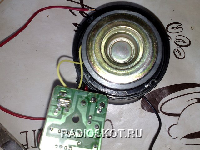
The idea of creating a laser alarm system was not new, but I just couldn’t find the time to assemble it. And now the weekend has finally arrived. A ready-made, simple car alarm was purchased at the store for $3. A compact piezoelectric head, inside of which the electrical alarm circuit itself is assembled.
When connected to a power source, the alarm makes a very high-pitched sound that resembles a police car.
So, the task was to make a sensor for an alarm. The transmitter is a laser diode. A simple red laser pointer ($1) was also purchased from the store, then the diode with optics was removed from the factory body of the device.
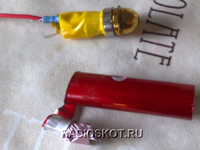
The laser button was unsoldered.

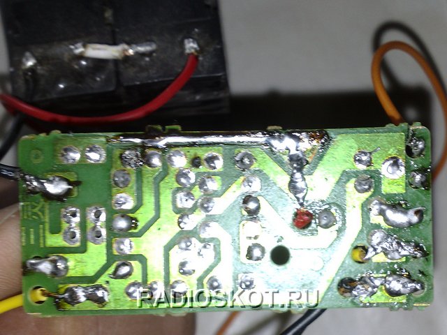
The minus of the laser diode is connected directly to the power source, and the plus is connected to the power source through a 30 ohm limiting resistor. The power source is a switching power supply from a DVD player, since the unit produces the voltage we need 6 volts.

The photodiode is used from a KODAK camera. The circuit is designed in such a way that in the presence of light, the photodiode does not allow the transistors to open, since its resistance is greater than the resistance of the 100K resistor, therefore current will flow through the photodetector. See the figure for the electrical circuit of a simple alarm (click to enlarge).

As soon as the lighting weakens or disappears altogether, the resistance of the photodiode increases and current begins to flow through the 100K resistor to the base of the first transistor and the junction opens, after which the second transistor opens to the collector of which the alarm is connected. After the alarm is triggered, the relay instantly turns off the laser diode, this is done so that after the lighting is present, the alarm will not turn off until you turn it off yourself.
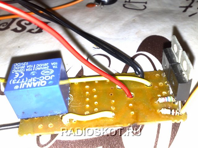
Any relay will do; I used a relay from an imported voltage stabilizer without any modifications.
It must be taken into account that the photo and laser diode must be at the same level so that the laser beam illuminates the photodiode; the latter must be in a dark case, since sunlight interferes with the correct operation of the device. Sensitivity to light depends on the value of the 100K resistor; as its resistance decreases, the sensor will be more sensitive.

The distance between the laser diode and the photodetector can reach several meters. When an object passes through the sensor activation zone, for a moment the laser beam falls on its body and does not illuminate the photodiode, at this moment an alarm is triggered and the laser is simultaneously turned off so that it does not illuminate the photoresistor later. This sensor can be used as a sensor to turn on the yard light, you just need to install a second relay instead of the alarm, which will turn on the light.
Discuss the article ALARM ELECTRICAL DIAGRAM
The consumer market for security systems is overflowing with various devices that can be used to effectively protect property and prevent “uninvited guests” from entering your home, apartment or garage. Among the many security systems, a special place is given to laser alarm systems, which are difficult to hack and bypass. The presence of such devices guarantees a high level of security of the protected object, using for this purpose the innovative capabilities of devices built on the basis of lasers. Systems of this kind are quite complex, which is reflected in their cost, which is sometimes several times higher than conventional systems. But you should not refuse to install a laser security system if you do not have the required funds to purchase it. For any user who has at least a little knowledge of electronics, there is an alternative option - this is a do-it-yourself laser alarm. It turns out that using several devices and components that are purchased for a nominal cost, you can create an effective laser alarm.
Scope of laser signaling
Due to its high efficiency, laser signaling has a fairly wide practical application. It can be installed both indoors and along the perimeter of the protected facility. This type of security complex is installed:
- in private houses and cottages;
- in apartments;
- in the offices of companies and enterprises;
- in banking institutions.
This type of alarm, given its high cost, should be installed at those facilities where valuables, jewelry or large financial assets are stored. In such cases, the use of laser security systems is justified and cost-effective.
How does laser alarm work?
The main elements of a security device are a source of laser radiation and a photodetector that receives this radiation. When a laser beam hits a sensitive photocell, its electrical resistance is several ohms. When the laser beam is interrupted, there will be a sharp increase in the resistance of the photocell, which, through the relay, causes an effect on external actuators that trigger the alarm.
Advantages
- The laser security system is highly mobile - its modules can be moved from place to place and located in different places;
- lasers can easily be hidden in a protected object - thanks to this, the criminal may not even suspect that the alarm has gone off until security officials arrive;
- elements of the laser security system do not spoil the appearance of the object and easily fit into any interior;
- the alarm system can work with sound sirens, without them, with notification to the central control panel of the security company;
- Do-it-yourself laser signaling can be created quite simply from improvised means.
Flaws
The disadvantages of this type of security systems include:
- high price of the kit;
- complexity of installation and configuration.
Necessary components for DIY laser signaling
If you are thinking about how to make a laser alarm at home, then you should purchase several components with the help of which you will create your own security system. For a simple laser alarm you will need:
- laser pointer – will play the role of a laser beam generator;
- photocell - a device with a replaceable resistance that changes when exposed to light;
- relay - it will be used to switch external actuators in the form of sound sirens, etc.;
- installation accessories;
- body parts;
- switching conductors;
- tools and materials for soldering.
All of the listed parts can be purchased at any radio market and store, and some of them can remain at home as components for various household appliances.
Variant of a simple laser signaling circuit
Below is an alarm on a laser pointer, a circuit that can be built using a laser emitter and an NE555 timer, which will control the operation of the alarm.

This circuit uses a photoresistor as a receiver-detector of a laser beam, which, when irradiated by a laser, has a small resistance, and when the beam disappears, its electrical resistance increases sharply. As the resistance increases, the microcircuit turns on an external device in the form of an audible siren.
Collection process
When creating a laser alarm with your own hands, the circuit may have a regular laser pointer or a children's toy laser as an emitter. Such emitters are powered by three small batteries, which are not enough for long-term operation. Therefore, the operating voltage for the laser should be supplied from a power supply of the appropriate rating. If this is not at hand, you can upgrade any low-voltage unit by adding a resistor to its circuit, which allows you to reduce the output voltage to the required value.
A three-pin relay system can be used as a relay, which turns off the laser and turns on the external siren. You can purchase a relay ready-made or make it yourself by remaking the relay assembly of some unnecessary device.
A wired communication line is connected to the relay contacts, which connects the sound siren with a photocell, which, when its resistance increases, ensures that the relay operates. In addition to the siren, the power line of the laser itself is also switched on via a relay. This is done so that if the alarm is triggered when the laser beam is interrupted, it will not turn off again when the object blocking it does not leave the overlap zone. In this case, the siren will sound until the alarm is turned off using a special button.
Installation at home
Note!
Installation of laser alarm systems at home should be carried out in those places that are most dangerous for penetration. For example, entrance doors or balcony doors - if the house is one-story or the apartment is located on the ground floor.
When installing, you should adhere to the rules that the laser signaling circuit must have the correct geometry. In this case, the security complex will work correctly and provide the required security.
The laser beam emitter and the photodetector must be located opposite each other on the same line so that the beam hits the center of the photocell. The light-sensitive element should be placed in a black tube to prevent it from being exposed to external light.


The button that turns the alarm on/off and the wiring to it should be located and routed covertly so that an attacker cannot turn it off on his own.
If you place a series of mirrors in a certain geometry between the emitter and the photodetector, you can get an excellent security device - a laser stretcher of this type will cover a fairly large area. If the laser beam is interrupted anywhere, an alarm will be triggered.
Conclusion
The use of inexpensive elements that can be purchased for a nominal price allows you to create highly effective security systems that are able to respond to any movement in the protected area. Therefore, it is not always necessary to spend a lot of money in order to be able to use modern security technologies; it is better to think a little about how to make a laser alarm yourself and implement this task using improvised means.
Laser radiation has found wide application in professional security systems. But from a radio amateur point of view, we are most interested in red laser pointers. Since the pointer has low radiation power, it is safe for people and animals, but laser radiation should not be directed directly into the eyes; this can cause dangerous eye disease.

The principle of operation of laser signaling is as follows: when an object enters the area of effect of the beam, the laser stops illuminating the photodetector. The resistance of the latter increases sharply and the relay turns off. The relay contacts also turn off the laser. This is a variant of the simplest scheme.
When a laser beam acts on a photoresistor, its resistance tends to zero, and when the laser is turned off, its resistance increases sharply and significantly. The photoresistor must be placed in a closed housing.
A ready-made module with a red emitter from a cheap Chinese pointer is used as a laser. The laser head is connected to the power source through a 5 ohm resistance. Active beam area from 10 to 100 meters.
I propose for consideration a laser signaling circuit, the basis of which is a comparator based on the TL072 operational amplifier. The reference voltage is formed by a voltage divider across resistances R2 and R3 and is supplied to the third pin of the TL072 microcircuit, and the compared voltage is sent to the second pin from the divider R1 and VD1.
At the moment the laser beam is interrupted, the voltage at the second terminal of the comparator decreases sharply relative to the third terminal, as a result of which a signal appears at the output of the op-amp that can control a siren or other actuator.

Resistance R4 is needed to protect against spontaneous operation if both inputs of the op-amp have equal voltage. Capacitance C1 protects the operation of the device from short-term interruption of the beam, for example, from insects.
The laser head housing must be lightproof. It can be glued together from black polystyrene. To avoid side illumination, it is recommended to glue a hood to the “window” of the photodiode. It can be made in the form of a square “well” from the same polystyrene. The photocell can be covered with a red light filter; it will slightly attenuate the laser radiation. To protect against strong electrical interference, the head is placed in a metal shield.
This scheme was described in detail in the magazine Radio No. 7 for 2002; you can download and read the article by clicking on the green arrow.
This circuit works as a security system and is a sensor for an attacker to cross a laser beam. The circuit consists of two main parts: a photo relay (VT1, VT2) and a time relay (VT3, VT4).

If the laser beam hits the photoresistor, then relay KV1 is turned off, and if the beam is interrupted, the relay will operate, its contact KV1.1 will turn on the time relay and return to its initial state. The time relay works according to the following algorithm. At the initial moment, when contact KV1.1 is open, the voltage on capacitor C1 tends to zero, and transistors VT3 and VT4 are closed, no current passes through the winding of relay KV2 and its contacts are open. When relay KV1 is triggered, capacitor C1 charges and immediately begins to discharge through the emitter junction of the third transistor and resistance R8, while transistors VT3 and VT4 open, relay KV2 turns on and connects the actuator with its contacts. At the end of the capacitor discharge process, the circuit returns to its initial state. Resistance R6 can be used to adjust the time delay.
This light alarm circuit is activated when the light level of the sensor suddenly drops, triggering an audible alarm. The device does not work when the brightness changes smoothly. To increase battery life, the audible alarm sounds from one to ten seconds, the sound time can be adjusted using the building resistance R5.

It is advisable to use laser radiation as a light source, but in extreme cases, ordinary lighting will do, but the circuit will work much worse. The sensitivity of the circuit can be changed by resistance R1. The light sensor is an ordinary photoresistor, the resistance of which is minimal when illuminated and maximum when darkened. Since the 555 timer chip has low power consumption, the alarm circuit consumes about 0.5mA in standby mode.
This practically simplest option consists of two circuits: a radiation circuit and a beam reception circuit. The receiver circuit includes an electromagnetic relay for connecting an external alarm.

The laser emitter circuit consists of a red Laser LED with a wavelength of 650 nm and a power of 5 mW. LD1 is powered from a 5 V source. Two auxiliary elements are connected in series with it: semiconductor diode D1 (1N4007) and resistance R1 with a nominal value of 62 Ohms. LD1 can be borrowed from Laser pointers.
The receiver circuit consists of a photoresistor that drives the relay using thyristor T1 (BT169). D2 (1N4007) protects the circuit from the back EMF pulse of the relay coil when thyristor T1 turns off.
An example of installing a laser tripwire alarm is shown in the left corner of the figure above.
The design is also based on the idea of using a red laser head from a laser pointer as a light source.

To eliminate the possibility of false triggering, the circuit has a time delay. If it is necessary to increase it, it is necessary to add capacitance C1 or increase the value of variable resistances R2 and R3. Instead of the NE555 timer, you can take its domestic analogue KR1006VI1. To prevent direct sunlight from entering the phototransistor, it is advisable to place it in a tube of a suitable diameter depending on the body of the photocell and a length of at least 25 cm. We cover the end with transparent glass to protect it from various living creatures. The inner surface of the tube can be painted dark.
The proposed design may be useful for protecting non-permanent openings - windows, passage doors - or installed along the perimeter of an open object. The operating principle is triggered when the laser beam is interrupted by an intruder. Despite its simplicity, the system turned out to be quite reliable and economical, and the red laser operating in short pulse mode is practically invisible to the intruder.
Figure 1. Laser security system transmitter diagram
The transmitter, the diagram of which is shown above, consists of a short pulse generator and a current amplifier loaded onto a laser pointer, which is easy to find in almost any stall. The generator is assembled using elements DD1.1, DD1.2 and, with the ratings of the frequency-setting circuit indicated in the diagram, operates at a frequency of about 5 Hz. Next, the signal goes to the differentiating circuit C2R3, which generates short pulses with a duration of about 10 μs. This not only makes the device economical (one six-volt battery type 476 is enough for more than a year of continuous operation of the transmitter), but also invisible to the intruder.
Next, the pulses are equalized in shape and amplitude by elements DD1.3, DD1.4 and are sent to an amplifier assembled on transistor VT1. The amplifier is loaded onto a laser pointer, which is modified - the batteries are removed and the cone-shaped tip is removed. Resistor R7, connected in series with a resistor “imprinted” into the laser flashlight board itself (its nominal value is about 50 Ohms), is current-limiting for the laser LED, toggle switch SA1 turns on the continuous operating mode of the emitter, necessary for adjusting the transmitter-receiver system.
For greater economy and frequency stability, the DD1 microcircuit is powered by a voltage reduced to 3-4 V, the excess is suppressed by resistor R6. The average current consumption by the transmitter does not exceed 10 μA; the LED consumes about 20 mA per pulse, so there is no power switch. The transmitter remains operational (of course, with a decrease in range) when the supply voltage is reduced to 4.5 V.

The receiver, the circuit of which is shown in Figure 2, is assembled on an integrated circuit DA1, the sensitive element is a photodiode FD263-01. When replacing it, you need to take into account the length of the illumination pulses - the response time of the LED to illumination should be 5-10 times lower than the laser pulse duration.
In its place, for example, FD320, FD-11K, FD-K-142, KOF122 (A, B) and many others will be able to work. In response to each transmitter flash, the receiver generates a high-level CMOS amplitude pulse at the output. It can be used for further processing. To exclude external illumination, the photodiode must be installed in an opaque tube that acts as a hood.
Setting up the system comes down to its alignment. This is done visually, aiming the laser beam at the photodetector as accurately as possible. To do this, switch SA1 to switch the transmitter to continuous radiation. After completing the adjustment, both the receiver and the transmitter must be firmly secured. In principle, such a system does not require “micron” adjustment. During the experiments, it worked reliably when the photodetector, spaced 50 m from the transmitter, was located in a circle of radiation scatter with a diameter of 30 cm.
Based on materials from “Radio” No. 7, 2002.
This type of alarm is one of the components of modern security systems. Their advantage is their reliability - they are practically unhackable and impossible to bypass. Thanks to laser signaling, the level of security of any object, in comparison with traditional methods and devices, increases.
Laser security systems have many advantages:
- Mobility: modules are easily transported from place to place, they can be located in different places;
- Lasers are easy to hide so that the criminal does not know about their presence until security officers appear;
- The elements that are part of the security system are easily combined with any interior and do not spoil it with their presence;
- Ability to work with sirens, with signal output to the remote control.
Their disadvantages include high cost; they are difficult to install and configure.
The basis of the alarm is a laser, which is included in the security system. The latter have a fairly high complexity, which is why they are expensive. You shouldn’t give up on them - you need to try to make a laser alarm with your own hands. As the developments of craftsmen show, this requires several devices and components that can be purchased quite cheaply. The result is an effective laser-based alarm system.
Homemade alarms use a laser and a photodetector. A beam emerges from the laser and is received by a photodetector. In this case, the resistance of the latter is close to zero. If the beam is blocked by something, the resistance of the photocell increases rapidly. This leads to an imbalance of the electronic circuit to which both devices are connected, to the activation of actuators and to the activation of an alarm.
If you want to make a laser alarm with your own hands, you should purchase: a laser pointer that will generate a laser beam; a photocell whose resistance changes under the influence of light flux; a relay that will connect, for example, a sound siren. A system cannot be made without tools and materials for soldering, wires, housing parts, and installation accessories.
The laser alarm circuit can be built based on the NE555 timer, which will control its operation.
The “positive” circuit from the power source is supplied to the “plus” of the sound siren; “negative” – to the 1st output of the timer. A jumper is installed between them through resistor R2 and photoresistor R3. From the jumper between the last elements there is a tap to the 6th output of the timer.
Further along the “positive” circuit, taps are arranged: through resistor R1 to the 2nd output of the timer and from it, through a breaker, to the “minus” of the siren; to the 4th, then to the 8th timer output. In addition, the 3rd output of the timer is connected to the breaker switch.
When a laser pointer beam falls on a photoresistor, its resistance is insignificant, therefore electric current flows through the first jumper of the circuit through resistor R2 and photoresistor R3. When the beam increases, the resistance of the photoresistor increases greatly and the flow of current through the specified jumper stops - it will go to the timer and from it to the siren, which with its sound will notify that someone has crossed the pointer beam.


