Infrared motion sensors. Motion sensor on MK PIC and PIR sensor Infrared motion sensor arduino
The Arduino motion sensor allows you to track the movement of objects that emit heat (people, animals) in a closed area. Such systems are often used in domestic conditions, for example, to turn on lighting in the entrance. In this article we will look at connecting PIR sensors in Arduino projects: passive infrared sensors or pyroelectric sensors that respond to movement. Small dimensions, low cost, ease of operation and lack of connection difficulties allow the use of such sensors in various types of alarm systems.
The design of a PIR motion sensor is not very complicated - it consists of a pyroelectric element that is highly sensitive (a cylindrical part with a crystal in the center) to the presence of a certain level of infrared radiation in the action area. The higher the temperature of an object, the greater the radiation. A hemisphere is installed on top of the PIR sensor, divided into several sections (lenses), each of which ensures that the thermal energy radiation is focused on different segments of the motion sensor. Most often, a Fresnel lens is used as a lens, which, due to the concentration of thermal radiation, allows you to expand the sensitivity range of the Arduino infrared motion sensor. 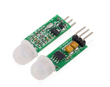
The PIR sensor is structurally divided into two halves. This is due to the fact that for an alarm device it is the presence of movement in the sensitivity zone that is important, and not the level of radiation itself. Therefore, the parts are installed in such a way that when one higher level of radiation is detected, a signal with a high or low value will be sent to the output.
The main technical characteristics of the Arduino motion sensor are:
- The detection zone for moving objects is from 0 to 7 meters;
- Tracking angle range – 110°;
- Supply voltage – 4.5-6 V;
- Operating current – up to 0.05 mA;
- Temperature range – from -20° to +50°С;
- Adjustable delay time from 0.3 to 18 s.
The module on which the infrared motion sensor is installed includes additional electrical wiring with fuses, resistors and capacitors.
The principle of operation of a motion sensor on Arduino is as follows:
- When the device is installed in an empty room, the radiation dose received by each element is constant, as is the voltage;
- When a person appears in a room, he first enters the viewing area of the first element on which a positive electrical impulse appears;
- When a person moves around the room, thermal radiation moves along with him, which hits the second sensor. This PIR element already generates a negative pulse;
- Multidirectional pulses are recorded by the electronic circuit of the sensor, which concludes that there is a person in the field of view of the Pir-sensor Arduino.
 For reliable protection from external noise, temperature and humidity changes, the elements of the Pir sensor on Arduino are installed in a sealed metal case. On the top of the case in the center there is a rectangle made of material that transmits infrared radiation (most often silicone-based). Sensing elements are installed behind the plate.
Connection diagram of the motion sensor to Arduino
 Connecting a Pir sensor to Arduino is not difficult. Most often, modules with motion sensors are equipped with three connectors on the back. The pinout of each device depends on the manufacturer, but most often there are corresponding inscriptions near the outputs. Therefore, before connecting the sensor to Arduino, you need to familiarize yourself with the symbols. One output goes to ground (GND), the second provides the necessary signal from the sensors (+5V), and the third is a digital output from which data is taken.
Connecting the Pir sensor:
- “Ground” – to any of the GND Arduino connectors;
- Digital output – to any digital input or output of Arduino;
- Power supply – +5V on Arduino.
The diagram for connecting the infrared sensor to Arduino is shown in the figure.
Example program
A sketch is a program code that helps check the functionality of the motion sensor after it is turned on. His simplest example has many disadvantages:
- Probability of false alarms due to the fact that it takes one minute for the sensor to self-initialize;
- Lack of executive-type output devices - relays, sirens, LED indicators;
- A short time interval of the signal at the sensor output, which must be delayed at the software level in the event of movement.
These disadvantages are eliminated by expanding the functionality of the sensor.
The simplest type of sketch, which can be used as an example of working with a motion sensor on Arduino, looks like this:
#define PIN_PIR 2 #define PIN_LED 13 void setup() ( Serial.begin(9600); pinMode(PIN_PIR, INPUT); pinMode(PIN_LED, OUTPUT); ) void loop() ( int pirVal = digitalRead(PIN_PIR); Serial. println(digitalRead(PIN_PIR)); //If motion is detected if (pirVal) ( digitalWrite(PIN_LED, HIGH); Serial.println("Motion detected"); delay(2000); ) else ( //Serial.print(" No motion"); digitalWrite(PIN_LED, LOW); ) )
Possible project options using the sensor
PIR sensors are indispensable in those projects where the main function of the alarm is to determine the presence or absence of a person within a certain work space. For example, in places or situations such as:
- Turning on the light in the entrance or in front of the front door automatically when a person appears in it;
- Turning on the lighting in the bathroom, toilet, corridor;
- An alarm is triggered when a person appears, both indoors and in the local area;
- Automatic connection of security cameras, which are often equipped with security systems.
PIR sensors are easy to use and do not cause difficulties when connecting, have a large sensitivity zone and can also be successfully integrated into any of the Arduino software projects. But it should be borne in mind that they do not have the technical ability to provide information about how many objects are in the coverage area, and how close they are to the sensor, and can also be triggered by pets.
The main sensitive element of motion and presence sensors is a pyroelectric infrared sensor. Pyroelectricity is the electrical potential that arises
in the material under the influence of infrared (IR) radiation.
A sensor that uses a material with these properties can respond to heat emitted by the human body. The PIR sensor (Pyroelectric InfraRed) has a circular radiation pattern (360°) with a rotation angle of 120°.
Special circuit solutions made it possible to create various infrared motion sensors to turn on lights and record the movement of people.
PIR sensor coverage areas
The product range of B.E.G. There are motion and presence sensors of various designs and purposes:
- for external use;
- for internal use;
- for wall mounting;
- for ceiling mounting
- designer sensors.
One of the main parameters of IR motion sensors is the coverage area. Ceiling sensors usually have a circular coverage area (360°). PIR wall motion sensors, depending on the model, have a coverage range from 120° to 280°.
In specific conditions, it is sometimes necessary to use a sensor with a non-standard viewing angle.
In such cases, closing plates (curtains) are used. They exclude heat sources (interference) or areas of the room from the detection zone.
The range of the sensor depends on how the person moves in relation to the sensor. If it moves in a direction perpendicular to the sensor, then the sensor has maximum range.
If the movement is towards the sensor (frontally), the coverage area is reduced by almost half. Sensors have a minimum range if movement occurs directly under the sensor.
PIR presence sensors from B.E.G. high sensitivity zone, and they respond to the slightest movements. The sensitivity of the sensor is adjustable.
When implementing a project, it is important to ensure that the sensor coverage areas cover the entire area to be monitored. To do this, several sensors are used with overlapping coverage areas, avoiding “dead” zones. To eliminate omissions and false positives, time delays are applied.

How to position PIR sensors correctly
A wall-mounted PIR motion sensor for outdoor use is installed at the entrance to the building.
There must be a path to the entrance in its area of effect. The sensor is the first to greet the visitor, enhancing the image of the establishment.
In corridors, special attention is paid to entrances. Sensors must be installed so that a person does not find himself in the dark even for a short time. Special ceiling motion sensors with a narrow detection range and long range have been developed for corridors.
Staircases are considered high-risk areas. Here, people should not fall due to insufficient lighting. Motion sensors are installed on the ceiling or on the wall of the landing like wall switches.

The peculiarity of lighting in an office is that in one room it is necessary to provide different illumination at different workplaces. It is necessary to take into account the intensity of natural light and be able to turn off the lighting in empty areas.
Therefore, each workplace needs its own lighting control scheme. Ceiling PIR presence sensors with the ability to expand the detection range can cope with this task.
In a school classroom or university auditorium, lighting is carried out taking into account daylight. The room is divided into zones in such a way as to ensure uniform illumination using adjustable artificial lighting.
Particular attention is paid to the area near the board. Those present must have a clear view of the teacher and the board, so reliable lighting and, preferably, additional manual control are necessary. In such rooms, ceiling presence sensors are used.

When automating the lighting of conference rooms and meeting rooms, an approach similar to that described above is used. In a store, pharmacy, or service enterprise, a motion sensor with a sound signal is installed near the entrance so that the staff pays attention to the entering visitor.
A large gym is divided into zones with independent control from ceiling sensors. It is also important to provide manual control: this will make it possible to provide lighting only where classes are taking place.
In an underground garage, it is necessary to ensure reliable control of the entrance areas and main passages. Possible “dead” zones are compensated by time delays. Only ceiling sensors are used here.
General requirements for installing PIR sensors
The range of PIR sensors depends on the direction of movement of the IR radiation sources. If, due to the large number of communications, it is impossible to install motion sensors on the ceiling, then they are placed on columns and walls.
The range of sensors should not be limited by trees, furniture and partitions (including glass). The optimal installation height for ceiling sensors is 2.5-3 meters, and wall switches from 1.1 to 2.2 meters. Sensors for high ceilings are placed at heights of up to 16 meters.
The range of PIR sensors is wide. They differ in purpose, technical parameters and design. To apply them with maximum efficiency at a specific site, it is better to use the services of professionals.
To B.E.G. Our specialists will give all the necessary advice. And to our blog so as not to miss useful materials about motion and presence sensors.
Hello everyone, today we will look at a device called a motion sensor. Many of us have heard about this thing, some have even dealt with this device. What is a motion sensor? Let's try to figure it out, so:
Motion sensor or displacement sensor - a device (device) that detects the movement of any objects. Very often these devices are used in security, alarm and monitoring systems. There are a great many forms of factors of these sensors, but we will consider the motion sensor module for connection to boards Arduino,and specifically from the company RobotDyn. Why this company? I don’t want to advertise this store and its products, but it was the products of this store that were chosen as laboratory samples due to the high-quality presentation of their products to the end consumer. So, we meet - motion sensor(PIR Sensor) from RobotDyn:


These sensors are small in size, consume little power and are easy to use. In addition, RobotDyn motion sensors also have silk-screened contacts, this is of course a small thing, but very pleasant. Well, those who use the same sensors, but only from other companies, should not worry - they all have the same functionality, and even if the contacts are not marked, the pinout of such sensors is easy to find on the Internet.
Main technical characteristics of the motion sensor (PIR Sensor):
Sensor operating area: from 3 to 7 meters
Tracking angle: up to 110 o
Operating voltage: 4.5...6 Volts
Current consumption: up to 50 µA
Note: The standard functionality of the sensor can be expanded by connecting a light sensor to the IN and GND pins, and then the motion sensor will only work in the dark.
Initializing the device.
When turned on, the sensor takes almost a minute to initialize. During this period, the sensor may give false signals; this should be taken into account when programming a microcontroller with a sensor connected to it, or in actuator circuits if the connection is made without using a microcontroller.
Detection angle and area.
The detection(tracking) angle is 110 degrees, the detection distance range is from 3 to 7 meters, the illustration below shows it all:

Adjustment of sensitivity (detection distance) and time delay.
The table below shows the main adjustments of the motion sensor; on the left there is a time delay regulator, respectively, in the left column there is a description of the possible settings. The right column describes the detection distance adjustments.

Sensor connection:
- PIR Sensor - Arduino Nano
- PIR Sensor - Arduino Nano
- PIR Sensor - Arduino Nano
- PIR Sensor - for light sensor
- PIR Sensor - for light sensor
A typical connection diagram is shown in the diagram below; in our case, the sensor is shown conventionally from the rear side and connected to the Arduino Nano board.

Sketch demonstrating the operation of the motion sensor (we use the program):
/* * PIR Sensor -> Arduino Nano * PIR Sensor -> Arduino Nano * PIR Sensor -> Arduino Nano */ void setup() ( //Establish a connection to the port monitor Serial.begin(9600); ) void loop() ( //Read the threshold value from port A0 //usually it is higher than 500 if there is a signal if(analogRead(A0) > 500) ( //Signal from the motion sensor Serial.println("There is movement!!!"); ) else ( / /No signal Serial.println("Everything is quiet..."); ) )
The sketch is a common test of the operation of the motion sensor; it has many disadvantages, such as:
- Possible false alarms, the sensor requires self-initialization within one minute.
- Rigid binding to the port monitor, no output actuators (relay, siren, LED indicator)
- The signal time at the sensor output is too short; when motion is detected, it is necessary to programmatically delay the signal for a longer period of time.
By complicating the circuit and expanding the functionality of the sensor, you can avoid the above-described disadvantages. To do this, you will need to supplement the circuit with a relay module and connect a regular 220-volt lamp through this module. The relay module itself will be connected to pin 3 on the Arduino Nano board. So the schematic diagram:

Now it's time to slightly improve the sketch that tested the motion sensor. It is in the sketch that a delay in turning off the relay will be implemented, since the motion sensor itself has too short a signal time at the output when triggered. The program implements a 10-second delay when the sensor is triggered. If desired, this time can be increased or decreased by changing the value of the variable DelayValue. Below is a sketch and video of the entire assembled circuit in action:
/* * PIR Sensor -> Arduino Nano * PIR Sensor -> Arduino Nano * PIR Sensor -> Arduino Nano * Relay Module -> Arduino Nano */ //relout - pin (output signal) for the relay module const int relout = 3; //prevMillis - variable for storing the time of the previous program scanning cycle //interval - time interval for counting seconds before turning off the relay unsigned long prevMillis = 0; int interval = 1000; //DelayValue - the period during which the relay is kept in the on state int DelayValue = 10; //initSecond - Initialization loop iteration variable int initSecond = 60; //countDelayOff - time interval counter static int countDelayOff = 0; //trigger - motion sensor trigger flag static bool trigger = false; void setup() ( //Standard procedure for initializing the port to which the relay module is connected //IMPORTANT!!! - in order for the relay module to remain in the initially off state //and not trigger during initialization, you need to write //the value HIGH to the input/output port , this will avoid false “clicking”, and will //preserve the state of the relay as it was before the entire circuit was put into operation pinMode(relout, OUTPUT); digitalWrite(relout, HIGH); //Everything is simple here - we wait until 60 ends cycles (initSecond variable) //lasting 1 second, during which time the sensor “self-initializes” for(int i = 0; i< initSecond; i ++) { delay(1000); } } void loop() { //Считать значение с аналогового порта А0 //Если значение выше 500 if(analogRead(A0) >500) ( //Set the motion sensor trigger flag if(!trigger) ( trigger = true; ) ) //While the motion sensor trigger flag is set while(trigger) ( //Execute the following instructions //Save in the currMillis variable //the value of milliseconds elapsed since the start //of program execution unsigned long currMillis = millis(); //Compare with the previous value of milliseconds //if the difference is greater than the specified interval, then: if(currMillis - prevMillis > interval) ( //Save the current value of milliseconds to a variable prevMillis prevMillis = currMillis; //Check the delay counter by comparing it with the value of the period //during which the relay should be kept in the ON state if(countDelayOff >= DelayValue) ( //If the value is equal, then: //reset the sensor activation flag movement trigger = false; //Reset the delay counter countDelayOff = 0; //Turn off the relay digitalWrite(relout, HIGH); //Abort the cycle break; ) else ( //If the value is still less, then //Increment the delay counter by one countDelayOff++; //Keep the relay in the on state digitalWrite(relout, LOW); ) ) ) )
The program contains the following structure:
unsigned long prevMillis = 0;
int interval = 1000;
...
unsigned long currMillis = millis();
if(currMillis - prevMillis > interval)
{
prevMillis = currMillis;
....
// Our operations are enclosed in the body of the structure
....
}
To clarify, it was decided to comment separately on this design. So, this design allows you to perform a parallel task in the program. The body of the structure operates approximately once per second, this is facilitated by the variable interval. First, the variable currMillis the value returned when calling the function is assigned millis(). Function millis() returns the number of milliseconds that have passed since the beginning of the program. If the difference currMillis - prevMillis greater than the value of the variable interval then this means that more than a second has already passed since the start of the program execution, and you need to save the value of the variable currMillis into a variable prevMillis then perform the operations contained in the body of the structure. If the difference currMillis - prevMillis less than the variable value interval, then a second has not yet passed between program scanning cycles, and the operations contained in the body of the structure are skipped.
Well, at the end of the article, a video from the author:
Please enable javascript for comments to work.
PIR (passive infrared) sensors allow you to detect movement.
Very often used in alarm systems. These sensors are small in size, inexpensive, consume little energy, are easy to operate, and are practically not subject to wear. In addition to PIR, such sensors are called pyroelectric and infrared motion sensors.
Pyroelectric motion sensor - general information
PIR motion sensors essentially consist of a pyroelectric sensing element (a cylindrical piece with a rectangular crystal in the center) that detects the level of infrared radiation. Everything around us emits a small level of radiation. The higher the temperature, the higher the radiation level. The sensor is actually divided into two parts. This is due to the fact that what is important to us is not the level of radiation, but the immediate presence of movement within its sensitivity zone. The two halves of the sensor are set up so that if one half picks up more radiation than the other, the output will generate a high or low value.
The module itself, on which the motion sensor is installed, also consists of additional electrical wiring: fuses, resistors and capacitors. Most inexpensive PIR sensors use the inexpensive BISS0001 ("Micro Power PIR Motion Detector IC") chips. This chip senses an external radiation source and performs minimal signal processing to convert it from analog to digital.
One of the basic models of pyroelectric sensors of this class looks like this:

Newer models of PIR sensors have additional outputs for additional configuration and installed connectors for signal, power and ground:

PIR sensors are great for projects where it is necessary to detect the presence or absence of a person within a certain workspace. In addition to the advantages of such sensors listed above, they have a large sensitivity zone. However, please note that pyroelectric sensors will not give you information about how many people are around or how close they are to the sensor. In addition, they can also work on pets.
General technical information
These specifications apply to PIR sensors sold in the Adafruit store. The operating principle of similar sensors is similar, although the technical characteristics may differ. So before working with a PIR sensor, familiarize yourself with its datasheet.
- Shape: Rectangle;
- Price: About $10.00 at Adafruit;
- Output signal: digital pulse high (3V) when there is movement and digital signal low when there is no movement. The pulse length depends on the resistors and capacitors on the module itself and varies in different sensors;
- Sensitivity range: up to 6 meters. Viewing angle 110° x 70°;
- Power: 3V - 9V, but the best option is 5 volts;
>To order from Aliexpress:
Operating principle of pyroelectric (PIR) motion sensors
PIR sensors are not as simple as they might seem at first glance. The main reason is the large number of variables that affect its input and output signals. To explain the basic workings of PIR sensors, we use the figure below.
The pyroelectric motion sensor consists of two main parts. Each part includes a special material that is sensitive to infrared radiation. In this case, the lenses do not particularly affect the operation of the sensor, so we see two sensitivity areas of the entire module. When the sensor is at rest, both sensors detect the same amount of radiation. For example, this could be radiation from a room or the outdoor environment. When a warm-blooded object (human or animal) passes by, it crosses the sensitivity zone of the first sensor, resulting in two different radiation values being generated on the PIR sensor module. When a person leaves the sensitivity zone of the first sensor, the values are leveled off. It is the changes in the readings of the two sensors that are recorded and generate HIGH or LOW pulses at the output.

PIR sensor design
The sensitive elements of the PIR sensor are installed in a sealed metal housing, which protects from external noise, temperature changes and humidity. The rectangle in the center is made of a material that transmits infrared radiation (usually a silicone-based material). Behind this plate two sensitive elements are installed.
Figure from Murata datasheet:

Figure from the RE200B datasheet:

The figure from the RE200B datasheet shows two sensitive elements:

The figure above shows the internal connection diagram.
Lenses
Infrared motion sensors are almost identical in structure. The main differences are sensitivity, which depends on the quality of the sensitive elements. In this case, optics plays a significant role.
The picture above shows an example of a plastic lens. This means that the sensitivity range of the sensor is two rectangles. But, as a rule, we need to provide large viewing angles. To do this, you can use lenses similar to those used in cameras. In this case, the lens for the motion sensor should be small, thin and made of plastic, although it adds noise to the measurements. That's why most PIR sensors use Fresnel lenses (picture from Sensors Magazine):

Fresnel lenses concentrate radiation, significantly expanding the sensitivity range of pyro sensors (picture from BHlens.com)

Figure from Cypress appnote 2105:

We now have a significantly larger sensitivity range. At the same time, we remember that we have two sensitive elements and we need not so much two large rectangles, but a large number of small sensitivity zones. To do this, the lens is divided into several sections, each of which is a separate Fresnel lens.
In the figure below you can see the individual sections - Fresnel lenses:

In this macro shot, notice that the texture of the individual lenses is different:

As a result, a whole set of sensitive areas is formed that interact with each other.
Pictures from the NL11NH datasheet:


Below is another drawing. Brighter, but less informative. Also, note that most sensors have a viewing angle of 110 degrees, not 90.
Figure from IR-TEC:

Connecting a PIR motion sensor

Most infrared motion sensor modules have three connectors on the back. Pinout may vary, so please check before connecting! Usually, corresponding inscriptions are made next to the connectors. One connector goes to ground, the second produces the signal we are interested in from the sensors, the third is ground. The supply voltage is usually 3-5 volts, DC. However, sometimes there are sensors with a supply voltage of 12 volts. Some large sensors do not have a separate signal pin. Instead, a relay is used with ground, power and two switches.
To prototype your device using an infrared motion sensor, it is convenient to use a circuit board, since most of these modules have three connectors, the distance between which is calculated exactly for the breadboard holes.

In our case, the red cable corresponds to power, black to ground, and yellow to signal. If you connect the cables incorrectly, the sensor will not be damaged, but will not work.
PIR motion sensor testing


Assemble the circuit according to the picture above. As a result, when the PIR sensor detects movement, a HIGH signal will be generated at the output, which corresponds to 3.3 V, and the LED will light up.
Please note that the pyroelectric sensor must “stabilize”. Install batteries and wait 30-60 seconds. During this time the LED may flash. Wait until the flashing stops and you can start waving your arms and walking around the sensor and watching the LED light up!
Configuring Sensor Restart
The pyroelectric motion sensor has several settings. We'll look at "restart" first.
After connecting, look at the back of the module. The connectors should be installed in the upper left corner of the L, as shown in the figure below.


Please note that with this connection option, the LED does not light constantly, but turns on and off when you move near it. This is the non-retriggering option.

Now install the connector in position H. After testing, it turns out that the LED is constantly on if someone moves within the sensor's sensitivity zone. This is the "restart" mode.
The picture below is from the datasheet of the BISS0001 sensor:

For most cases, the "restart" mode (connector in position H as shown in the figure below) is better.

Adjusting sensitivity
Many infrared motion sensors, including those from Adafruit, have a small potentiometer to adjust the sensitivity. Rotating the potentiometer clockwise adds sensitivity to the sensor.
Changing pulse time and time between pulses
When we consider PIR sensors, two "delay" times are important. First time period -Tx: how long the LED remains on after motion is detected. On many pyroelectric modules this time is adjusted by a built-in potentiometer. The second period of time is Ti: how long is it guaranteed that the LED will not light up when there is no movement. Changing this parameter is not so easy; you may need a soldering iron for this.
Let's take a look at the BISS datasheet:
The Adafruit sensors have a potentiometer marked TIME. This is a 1 mega ohm variable resistor added to the 10 kilo ohm resistors. Capacitor C6 has a capacitance of 0.01 microfarat, so:
Tx = 24576 x (10 kOhm + Rtime) x 0.01 µF
When the Rtime potentiometer is in the "zero" - completely counterclockwise - position (0 megohm):
Tx = 24576 x (10k ohms) x 0.01 µF = 2.5 seconds (approx.) When the Rtime potentiometer is turned fully clockwise (1megaohm):
Tx = 24576 x (1010 kOhm) x 0.01 µF = 250 seconds (approx.)
In the middle RTime position, the time will be about 120 seconds (two minutes). That is, if you want to track the movement of an object once per minute, turn the potentiometer 1/4 turn.
For older/different PIR sensor models
If your sensor does not have potentiometers, you can make adjustments using resistors.

We are interested in resistors R10 and R9. Unfortunately, the Chinese can do a lot. Including confusing inscriptions. The figure above shows an example that shows that R9 is confused with R17. Track the connection using the datasheet. R10 is connected to pin 3, R9 - to pin 7.
For example:
Tx is = 24576 * R10 * C6 = ~1.2 seconds
R10 = 4.7K and C6 = 10 nanofarads
Ti = 24 * R9 * C7 = ~1.2 seconds
R9 = 470K and C7 = 0.1 microfarad
You can change the delay time by installing different resistors and capacitors.
Connecting a PIR motion sensor to Arduino
Let's write a program to read values from a pyroelectric motion sensor. Connecting a PIR sensor to a microcontroller is simple. The sensor produces a digital signal, so all you need to do is read the HIGH (motion detected) or LOW (no movement) signal from the Arduino pin.
Do not forget to install the connector in position H!
Apply 5 volt power to the sensor. Connect the earth with the earth. After this, connect the signal pin from the sensor to the digital pin on the Arduino. In this example, pin 2 is used.

The program is simple. Essentially, it monitors the state of pin 2. Namely: what signal is on it: LOW or HIGH. In addition, a message is displayed when the state of the pin changes: there is movement or there is no movement.
* PIR motion sensor check
int ledPin = 13; // initialize the pin for the LED
int inputPin = 2; // initialize the pin to receive a signal from the pyroelectric motion sensor
int pirState = LOW; // start the program, assuming there is no movement
int val = 0; // variable for reading pin state
pinMode(ledPin, OUTPUT); // declare LED as OUTPUT
pinMode(inputPin, INPUT); // declare the sensor as an INPUT
Serial.begin(9600);
val = digitalRead(inputPin); // read the value from the sensor
if (val == HIGH) ( // check if the read value matches HIGH
digitalWrite(ledPin, HIGH); // turn on the LED
if (pirState == LOW) (
// we just turned it on
Serial.println("Motion detected!");
pirState = HIGH;
digitalWrite(ledPin, LOW); // turn off the LED
if (pirState == HIGH)(
// we just turned it off
Serial.println("Motion ended!");
// we output the change to the serial monitor, not the state
Don't forget that you don't always need a microcontroller to work with a pyroelectric sensor. Sometimes you can get by with a simple relay.
HC-SR501 Space Sensor Overview
The HCSR501 motion (or presence) sensor module based on the pyroelectric effect consists of a 500BP PIR sensor (Fig. 1) with additional electrical isolation on the BISS0001 chip and a Fresnel lens, which is used to increase the viewing radius and amplify the infrared signal (Fig. 2). The module is used to detect the movement of objects emitting infrared radiation. The sensitive element of the module is a 500BP PIR sensor. Its operating principle is based on pyroelectricity. This is the phenomenon of the appearance of an electric field in crystals when their temperature changes.The operation of the sensor is controlled by the BISS0001 chip. There are two potentiometers on the board, with the first one you can adjust the object detection distance (from 3 to 7 m), with the second one you can adjust the delay after the first activation of the sensor (5 - 300 sec). The module has two modes – L and H. The operating mode is set using a jumper. Mode L – single actuation mode, when a moving object is detected, the OUT output is set to a high signal level for the delay time set by the second potentiometer. During this time, the sensor does not respond to moving objects. This mode can be used in security systems to send an alarm to the siren. In H mode, the sensor is triggered every time motion is detected. This mode can be used to turn on the lights. When the module is turned on, it is calibrated; the calibration duration is approximately one minute, after which the module is ready for operation. It is advisable to install the sensor away from open light sources.
Figure 1. 500BP PIR sensor

Figure 2. Fresnel lens
HC-SR501 Specifications
- Supply voltage: 4.5-20 V
- Current consumption: 50 mA
- Output voltage OUT: HIGH – 3.3 V, LOW – 0 V
- Detection interval: 3-7m
- Duration of delay after activation: 5 - 300 sec
- Viewing angle up to 120
- Blocking time until next measurement: 2.5 seconds.
- Operating modes: L - single triggering, H - triggering with each event
- Operating temperature -20 to +80C
- Dimensions 32x24x18 mm
Connecting an infrared motion sensor to Arduino
The module has 3 outputs (Fig. 3):- VCC - power supply 5-20 V;
- GND - ground;
- OUT - digital output (0-3.3V).

Figure 3. Pin assignment and setup of HC-SR501
Let's connect the HC-SR501 module to the Arduino board (Connection diagram in Fig. 4) and write a simple sketch that will signal with a sound signal and a message to the serial port when a moving object is detected. To record operations by the microcontroller, we will use external interrupts at input 2. This is an int0 interrupt.

Figure 4. Connection diagram for connecting the HC-SR501 module to the Arduino board
Let's upload the sketch from Listing 1 to the Arduino board and see how the sensor reacts to obstacles (see Fig. 5). Let's set the module to operating mode L. Listing 1 // Sketch for review of the HC-SR501 motion/presence sensor // site // contact for connecting the sensor output #define PIN_HCSR501 2 // trigger flag boolean flagHCSR501=false; // speaker connection pin int soundPin=9; // sound signal frequency int freq=587; void setup() ( // initialize the serial port Serial.begin(9600); // start interrupt processing int0 attachInterrupt(0, intHCSR501,RISING); ) void loop() ( if (flagHCSR501 == true) ( // Message in serial port Serial.println("Attention!!!"); // sound alarm for 5 seconds tone(soundPin,freq,5000); // reset the trigger flag flagHCSR501 = false; ) ) // interrupt processing void intHCSR501() ( // setting the sensor trigger flag flagHCSR501 = true; )

Figure 5. Serial port monitor output
Using potentiometers, we experiment with the duration of the signal at the OUT output and the sensitivity of the sensor (object fixation distance).
Usage example
Let's create an example of sending an SMS when a motion/presence sensor is triggered at a protected object. For this we will use a GPS/GPRS shield. We will need the following parts:- Arduino Uno board
- GSM/GPRS Shield
- NPN transistor, for example C945
- resistor 470 ohm
- speaker 8 Ohm 1W
- wires

Figure 6. Connection diagram
When the sensor is triggered, we call the procedure for sending sms with a text message Attention!!! to PHONE number. The contents of the sketch are presented in Listing 2. The GSM/GPRS shield in the SMS sending mode consumes current up to 2 A, so we use an external power supply of 12V 2A. Listing 2 // Sketch 2 for review of the HC-SR501 motion/presence sensor // sending sms when the sensor is triggered // site // contact for connecting the sensor output #define PIN_HCSR501 2 // trigger flag boolean flagHCSR501 false; // speaker connection pin int soundPin=9; // sound signal frequency int freq=587; // SoftwareSerial library #include
Frequently asked questions FAQ
1. The module does not work when the object moves- Check that the module is connected correctly.
- Adjust the trigger distance using the potentiometer.
- Adjust the signal duration delay using the potentiometer.
- Set the jumper to single operation mode L.
We also recommend
 Why do yucca leaves curl? Why do yucca leaves droop?
 Fertilizing watermelon: in a greenhouse, in open ground, during planting, after
 When to plant garlic for the winter in the Urals When to plant garlic in the Urals
 When to plant garlic in the Urals Planting spring garlic in the spring in the Urals
 Where to put a Christmas tree according to Feng Shui?
 Cauliflower and white cabbage seedlings: diseases and their treatment