Internal interaction with the customer during the design. Customer and Contractor - relationships as the basis for the success of the project
The general stages of interaction with the customer are the following points:
- - Preliminary communication with the customer: identifying the goals and objectives of the project, identifying the main requirements for the future system, preliminary acquaintance with the Customer's company, preliminary assessment of the timing and cost of the project, preparation and transfer of the Commercial Offer to the Customer.
- - Detailed survey and collection of customer requirements: determination of the composition of the project team, collection of requirements for the system, interviewing key users and technical specialists of the Customer, development and approval of the Terms of Reference.
- - Development and testing of the system: after the development of the system or a certain part of its functionality, a demonstration to the Customer is carried out. This is followed by the stage of detection and elimination of errors, if there are none, acceptance tests.
- - Trial operation of the system: deployment of the system on the Customer's side, user training, collection of comments and suggestions for improving the system, elimination of comments.
- - Industrial operation of the system: independent operation by the Customer, contacting the Company's support service (if necessary), collecting wishes for the development of the system.
An important form of interaction with the customer is the documentation developed during the implementation of the project in accordance with the requirements of GOST 34 and RUP.
Working groups are formed for specific project tasks. Synchronization of actions is carried out through the council of delegates from the working groups. Members of the working groups independently develop the principles of interaction in the group. Groups can involve members of other groups in solving problems. Successful forms of interaction both within groups and between groups can be adopted by new project participants
The world has long recognized that project management is a special area of management, the application of which gives tangible results. Professionals in this field are highly valued (in the US it is the third-highest-paying profession after lawyers and doctors), and project management methodology itself has become the de facto management standard in many thousands of enterprises and is used to varying degrees in almost all large corporations. Last year, ANSI project management standards were adopted, and a draft of ISO 10006 project management standards was developed.
Today, the process of creating complex software applications cannot be imagined without dividing into life cycle stages. Under the life cycle of the program, we mean the set of stages:
- Analysis of the subject area and creation of technical specifications (interaction with the customer)
- Program structure design
- Coding (a set of program code according to project documentation)
- Testing and Debugging
- Program implementation
- Program support
- Disposal
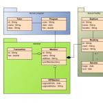
UML is a graphical language for visualization, description of parameters, design and documentation of various systems (programs in particular). Diagrams are created using special CASE tools such as Rational Rose (http://www-01.ibm.com/software/rational/) and Enterprise Architect (http://www.sparxsystems.com.au/). A single information model is built on the basis of UML technology. The above CASE tools are capable of generating code in various object-oriented languages, and also have a very useful reverse engineering feature. (Reverse engineering allows you to create a graphical model from the existing program code and comments to it.)
Consider the types of diagrams for visualizing the model (these are must-haves, although there are many more types):
Use Case Diagram
The designed system is represented as a set of entities or actors interacting with the system using so-called precedents. In this case, an actor (actor) or an actor is any entity that interacts with the system from the outside. In other words, each use case defines a certain set of actions that the system performs when talking to an actor. At the same time, nothing is said about how the interaction of actors with the system will be implemented.Class diagram (class diagram)
The class diagram serves to represent the static structure of the system model in the terminology of object-oriented programming classes. A class diagram can reflect, in particular, various relationships between individual entities of the subject area, such as objects and subsystems, and also describes their internal structure (fields, methods ...) and types of relationships (inheritance, implementation of interfaces ...). This diagram does not provide information about the time aspects of the system operation. From this point of view, the class diagram is a further development of the conceptual model of the designed system. At this stage, knowledge of the OOP approach and design patterns is essential.
State diagram (statechart diagram)
The main purpose of this diagram is to describe the possible sequences of states and transitions that together characterize the behavior of a model element during its life cycle. The state diagram represents the dynamic behavior of entities, based on the specification of their response to the perception of some specific events.
Sequence diagram
Appropriate interaction diagrams are used to model the interaction of objects in the UML language. Interactions of objects can be considered in time, and then a sequence diagram is used to represent the timing of the transmission and reception of messages between objects. Interacting objects exchange some information with each other. In this case, the information takes the form of complete messages. In other words, although the message has information content, it acquires the additional property of exerting a directed influence on its recipient.
Collaboration diagram
In the diagram of cooperation, the objects participating in the interaction are depicted in the form of rectangles, containing the name of the object, its class, and, possibly, attribute values. As in the class diagram, the associations between objects are indicated in the form of various connecting lines. In this case, you can explicitly specify the names of the association and the roles that objects play in this association.Unlike a sequence diagram, a collaboration diagram only depicts relationships between objects that play certain roles in an interaction.

Component Diagram
The component diagram, unlike the previously discussed diagrams, describes the features of the physical representation of the system. The component diagram allows you to determine the architecture of the system being developed by establishing dependencies between software components, which can be source, binary, and executable code. In many development environments, a module or component corresponds to a file. The dotted arrows connecting modules show dependency relationships similar to those that occur when compiling program source code. The main graphical elements of a component diagram are components, interfaces, and dependencies between them.
Deployment diagram
The deployment diagram is designed to visualize the elements and components of the program that exist only at the stage of its execution (runtime). In this case, only program instance components that are executable files or dynamic libraries are presented. Those components that are not used at runtime are not shown in the deployment diagram.A deployment diagram contains graphical representations of processors, devices, processes, and the relationships between them. Unlike logical representation diagrams, the deployment diagram is the same for the system as a whole, since it must fully reflect the features of its implementation. This diagram essentially completes the OOAP process for a particular software system, and its development is usually the last step in model specification.

This concludes our overview of diagrams in particular and design in general. It is worth noting that the design process has long become a software development standard, but often you have to deal with a beautifully written program, which, due to the lack of proper documentation, acquires unnecessary side functionality, crutches, becomes cumbersome and loses its former quality. =(
I am convinced that a programmer is primarily a coder - he should NOT communicate with the customer, should NOT think about the architecture of the system, should not invent an interface to the program, he should only code - implement algorithms, functionality, appearance, usability, but no more …. The designer, starting from abstract diagrams (describing the subject area) to diagrams representing the data structure, classes and processes of their interaction, must describe everything step by step in detail. That is, the complexity of the work and the salary of a designer should be an order of magnitude higher than that of a programmer == coder. Sorry for the rant....
1.1. Interaction with Customers (Main functions)
1.1.1. Order search
7.2.3.1. For product information
1.1.2. Pre-contract work with the Customer
Regulatory documents
2.2.1.2.1. Pre-contractual work with the Customer STP-1-01
ISO9000:2000 Quality Management System Requirements Clause 7
7.2.1.1. Customer requirements for products, including requirements for availability, delivery and maintenance
7.2.2.4. Determination of the ability to achieve compliance with certain requirements
// Analysis of product requirements / Processes related to the consumer / SALES OF PRODUCTS
1.1.3. Formation of Terms of Reference
Regulatory documents
2.2.1.2.2. The procedure for the analysis and conclusion of the contract STP-2-01 // Standards of the Enterprise Enterprise Ellat (STP) / Documents of the quality management system / Internal regulatory documents / Regulations
ISO9000:2000 Quality Management System Requirements Clause 7
7.2.1.2. Requirements not specified by the customer, but necessary for the intended or specified use // Definition of customer requirements / Customer related processes / PRODUCT SALES
7.2.1.3. Product-related obligations, including mandatory requirements and legal provisions // Definition of customer requirements / Customer related processes / PRODUCT SALES
// Analysis of product requirements / Processes related to the consumer / SALES OF PRODUCTS
7.2.2.2. Confirmation of consumer requirements prior to their acceptance, if the consumer does not provide a written statement of requirements // Analysis of product requirements / Processes related to the consumer / SALES OF PRODUCTS
7.2.2.3. Clarification of changes in the requirements of the contract or order that differ from those previously submitted (for example, by bidding or links) // Analysis of product requirements / Processes related to the consumer / SALES OF PRODUCTS
7.3.1.1. Determination of the stages of the design and/or development processes
7.3.2.2. Applicable legal and regulatory requirements
7.3.2.3. Applicable data derived from similar previous developments // Input data for design and development / Design and development / PRODUCT SALES
7.3.2.4. Other requirements important for design and development // Input data for design and development / Design and development / PRODUCT SALES
7.3.4.1. Assessing the ability to meet requirements
1.1.4. Conclusion of Agreements
Regulatory documents
2.2.1.2.3. Regulations on contractual work with the Customer (STP-3-01) // Enterprise Standards Ellat (STP) / Documents of the quality management system / Internal regulatory documents / Regulations
1.1.5. Monitoring the fulfillment of contractual obligations
Regulatory documents
2.2.1.2.3.2. The procedure for analyzing changes and making changes to the Contractual Documents // Regulations on contractual work with the Customer (STP-3-01) / Enterprise Standards Ellat (STP) / Documents of the quality management system / Internal regulatory documents / Regulations
2.2.1.2.4.1. Procedure for handling complaints and claims of the Customer
2.2.1.2.4.2. The procedure for eliminating the comments of the Customer // Regulations on corrective and preventive actions (STP-4-01) / Ellat Enterprise Standards (STP) / Quality management system documents / Internal regulatory documents / Regulations
ISO9000:2000 Quality Management System Requirements Clause 7
7.2.3.2. Processing requests, contracts, orders, including changes // Communication with the consumer / Processes related to the consumer / SALES OF PRODUCTS
1.2. Project Work Scheduling (Main Functions)
1.2.1. Clarification of the composition of the complex and scope of development
Regulatory documents
// Enterprise Standards Ellat (STP) / Documents of the quality management system / Internal regulatory documents / Regulations
ISO9000:2000 Quality Management System Requirements Clause 7
7.2.2.1. Definition of product requirements // Analysis of product requirements / Processes related to the consumer / SALES OF PRODUCTS
1.2.2. Project Quality Assurance Planning
Regulatory documents
2.2.1.2.5. Composition and procedure for developing a project quality assurance program (STP-5-01) // Enterprise Standards Ellat (STP) / Documents of the quality management system / Internal regulatory documents / Regulations
ISO9000:2000 Quality Management System Requirements Clause 7
- 7.1.1. Setting quality goals for a product, project or contract
7.1.3. Definition of review and approval activities and acceptance criteria // Planning of sales processes / SALES OF PRODUCTS
7.2.2.5. Fixing the results of the analysis and subsequent follow-up actions (see clause 5.5.7) // Analysis of product requirements / Processes related to the consumer / SALES OF PRODUCTS
7.3.1.2. Definition of review, verification and approval activities for each design and/or development stage // Design and development planning / Design and development / PRODUCTS SALES
1.2.3. Formation of private technical specifications for the development of the components of the complex
Regulatory documents
2.2.1.2.7. Project implementation technology. Stages and order of work (STP-7-01) // Enterprise Standards Ellat (STP) / Documents of the quality management system / Internal regulatory documents / Regulations
1.2.4. Project planning
Regulatory documents
// Enterprise Standards Ellat (STP) / Documents of the quality management system / Internal regulatory documents / Regulations
ISO9000:2000 Quality Management System Requirements Clause 7
7.1.2. Determination of the need for establishing processes and documentation, providing resources and infrastructure specific to the product // Planning of sales processes / SALES OF PRODUCTS
1.2.5. Coordination and operational control of work performance
Regulatory documents
2.2.1.2.4.3. Corrective Action Procedure // Regulations on corrective and preventive actions (STP-4-01) / Ellat Enterprise Enterprise Standards (STP) / Quality management system documents / Internal regulatory documents / Regulations
2.2.1.2.6. Regulation on work planning (STP-6-01) // Enterprise Standards Ellat (STP) / Documents of the quality management system / Internal regulatory documents / Regulations
ISO9000:2000 Quality Management System Requirements Clause 7
7.3.4.2. Identification of problems and development of proposals for follow-up actions // Design and Development Analysis / Design and Development / PRODUCT MAILING
7.3.7. Design and development change management
1.3. Development of design, software and operational documentation (Main functions)
1.3.1. Development of documentation for the hardware of the complex
Regulatory documents
2.2.1.2.7. Project implementation technology. Stages and order of work (STP-7-01) // Enterprise Standards Ellat (STP) / Documents of the quality management system / Internal regulatory documents / Regulations
2.3.3.3. Work plan for the hardware development and production department
1.3.2. Development of the software part of the complex
Regulatory documents
2.2.1.2.7. Project implementation technology. Stages and order of work (STP-7-01) // Enterprise Standards Ellat (STP) / Documents of the quality management system / Internal regulatory documents / Regulations
2.3.3.4. Work plan for software development and production department // Programs and action plans / Organizational and administrative documents of the company / Regulations
1.3.4. Analysis and approval of design results
Regulatory documents
2.2.1.2.7. Project implementation technology. Stages and order of work (STP-7-01) // Enterprise Standards Ellat (STP) / Documents of the quality management system / Internal regulatory documents / Regulations
ISO9000:2000 Quality Management System Requirements Clause 7
7.3.3.1. Conform to design and development input requirements
7.3.3.2. Provide appropriate information for manufacturing and service operations (see 7.5) // Design and development output / Design and development / PRODUCT MAILING
7.3.3.4. Determine the characteristics of the product that are essential for its safe and proper use. // Design and development output / Design and development / PRODUCT MAILING
7.3.5.1. Conformity of output data to input requirements // Design and Development Verification / Design and Development / PRODUCT SALES
7.3.6. Approval of design and development results // Design and development / SALES PRODUCTS
- Education, Development, Trainings
Keywords:
1 -1
Consider the full scheme of interaction with the customer on the example of website development. Graphically, the stages of interaction can be represented as the following figure:
Primary is call or e-mail, which are processed by the account manager. The manager talks about the services of the Beehive company, gives answers to all questions of interest and explains the further process of interaction to the customer.
* It is worth noting that the customer is allocated a personal manager for the entire period of his project, who is ready to answer all questions and help in solving all problems.
Next, the manager helps to complete brief form for the development of a website that contains the necessary clarifying questions on the subject of cooperation and adds a contact to the internal CRM system (Customer Relationship Management System).
The data is entered into the system to securely store all the necessary customer data and to ensure the quality development of the site as a whole.
Based on the completed brief, Beehive specialists prepare individual commercial offer with a description of the timing and cost of work and the manager sends it to the customer for consideration.
Next comes the process of agreeing on the terms of cooperation, the result of which is treaty. To speed up the start of work, the contract is signed by both parties and the parties exchange scanned copies of the contract. The originals of the contract are sent by registered mail (hereinafter, all paper copies are exchanged by mail or courier). After the party receives the original in paper form, one copy is sent back by post.
*The process from calling to signing the contract usually takes no more than 1-2 days.
After signing the contract and exchanging electronic scanned copies, the customer pays an advance, the amount of which is usually 50% of the total contract amount.
After receiving an advance payment and conducting an analysis of the subject area, the stage of development and approval begins terms of reference (TOR), where all the requirements for the site being developed are prescribed, schemes are given and a detailed prototype of the entire site is created. TK is a mandatory annex to the contract, approved by both parties and signed in the same way as the contract.
* It should be understood that the terms of reference is a very important document for both the contractor and the customer. It allows you to design and execute an Internet project with high quality and on time.
After all requirements are approved, the customer is sent list of necessary text and graphic materials, which the customer must provide before the start of the development stage (i.e. during the development of the design layout by the contractor, the customer collects and provides all the necessary materials). This list may include: a description of the company, with whom they cooperate, what awards and certificates they have, prices and price lists, a product catalog and description of goods, a description of services, contact information published on the site, etc.
Sometimes it is difficult for the customer to describe his services himself or there is simply no time for it. In this case, the contractor is ready to complete the work on writing the missing content for the site (pictures, texts, videos, etc.).
* Providing the customer with the necessary materials is critical because:
- it is necessary to correctly enter all the content provided by the customer into the layout of the site at once (it makes no sense to do extra work);
- the technological process of the performer is scheduled literally "by the minute" and we do not want to violate it and incur additional costs;
- filling an Internet project with test information also makes no sense (firstly, the amount of unnecessary work again increases; secondly, search engines can pessimize a hosted site with test content; thirdly, your potential customers may have a negative attitude towards the site, which contains obviously useless information);
- It is important for both you and us to complete the project professionally and on time.
* Dear customers, please do not delay the development of your own site and profit from it. Provide content on time! Otherwise, the project will be frozen until we receive information from you and, accordingly, the deadline for submitting the site has been postponed. If there is no time to collect and write information, order writing texts and photo processing to us, it's inexpensive.
In parallel, a working group for the project is created and the stage starts design layout development future site.
After the design layout is ready, it is sent to the customer for approval. Once approved, the mockup becomes a valid design.
* Depending on the complexity of the project, the customer may be given access to the project management system (for example, Redmine), where you can upload the necessary project resources, monitor the development stages and publish comments.
For further continuation of work, it is obligatory to receive from the customer all the necessary materials, the list of which was sent to the customer earlier.
As soon as the missing materials are received. An important site development stage in accordance with the approved TOR.
This stage includes a large number of types of work: this is a cross-browser layout of site layouts, development of the necessary design templates for the selected content management system (CMS), installation and configuration of the CMS itself, installation of the necessary modules and components, development of missing modules, a comprehensive study of website operation algorithms , filling the site with content, deploying the project on the technical domain and moving on to testing.
Testing of the Internet project is carried out by the contractor's specialists, all errors and comments are eliminated, the site is fine-tuned for work.
As soon as the work is completed and testing of the site on the technical domain is completed, the handover stage. Here, on the part of the customer, the fulfillment of the requirements of the TOR and the entire process of the functioning of the Internet project are checked.
After the customer makes a decision on the full compliance of the site with the requirements of the TOR, the site is transferred to the customer and the project is published on the hosting.
The result and confirmation of the delivery and acceptance of works is a workable site and an act of acceptance, which is signed by both parties. The signed act, together with the entire set of documents for accounting, is sent by mail.
After signing the acceptance certificate, the customer, in accordance with the contract, pays the remaining cost of the work.
After the final calculation, along with the documents and the website, the customer receives a user manual, a copy of the site on DVD and free technical support within 2-4 weeks from the date of acceptance of the site.
In this diagram, we tried to fully reflect all aspects of interactions from the initial call to the delivery of the project. For simple projects, some of the steps may be combined or omitted. But in any case, everything is reflected in the contract.
The scheme of work for the services "Comprehensive website development", as well as "Website promotion" structurally repeats the process of interaction between the customer and the contractor described above and therefore does not require a detailed description.
We hope that the described scheme of interaction is transparent and understandable. If you still have questions, please
| Project: | Distribution of queries to the electronic catalog by search indices and search terms |
|---|---|
| Project scope: | 13.02.2006 - 05.06.2006 |
| Customer: | Scientific Library of Petrozavodsk State University. | Responsible: | Gorshkova Galina Anatolyevna, head of the department of computer processing of documents and creation of catalogs. Email mail: . Slave. tel.: 719602. Library: cab. 102. Guryev Dmitry Borisovich, leading programmer of the RCNIT. Email mail: . Slave. tel.: 784775. Internet center. |
| Instructor: | Kulakov Kirill Alexandrovich Email: . Office phone: 711015. Room 215 |
| Information for the instructor: | Group number 13 |
| Related Documents: | Project Overview Project Plan Work Schedule (Gantt Chart) Requirements Specification Design Test Implementation Document Test Document Customer Engagement Developer Relations Reports Development Progress Glossary User Guide |
First meeting with the client.
At the first meeting, the development team was introduced to the customer. The customer, in turn, spoke about the scientific library of PetrSU.
The library operates on the basis of the automated system "Foliant". The electronic catalog is part of the library system. Catalog search is carried out using queries. The operator generates search strings that may contain a large number of search indexes and search terms. Each request is recorded in a log table. This table contains data on the time of the request, the address of the client who made the request, the request itself, the result of the request.
The customer needs to constantly monitor the log table and provide some statistics on the use of search indexes.
The initial requirements for the project being implemented were also presented. One of the requirements is the efficient compilation of statistics. That is, statistics should be displayed after a reasonable time after sending the request. Due to this requirement, developers were encouraged to use server-side procedures in PL/SQL.
Second meeting with the client.
The customer provided the developers with a login and password to enter the electronic catalog system, providing copies of two tables for work - a log table and a table of search indexes.
Guryev Dmitry Borisovich acquainted us in more detail with the work in the Oracle SQL*Plus DBMS client. The team got acquainted with the work of the electronic catalog.
The "Foliant" system works on the basis of the RusMark standard, which contains about 99 fields. Each library working with AIBS "Foliant" selects the fields and subfields that it will use. There are special GOSTs that describe the rules for storing library data. Since there are a large number of fields, we created a system of search indexes. There are service and public indexes.
Directory users are divided into internal and external. Each department or employee is assigned its own rights. Each record about an object is parsed into separate elements and is not stored as a whole.
Third meeting with the customer.
The customer has provided us with clear requirements in writing.
The customer is interested in the following statistics:
- The number of requests to the electronic catalog.
- For the last month by day.
- Monthly accounting for the current year.
- Accounting by years.
- Create a history of information.
- The number of requests.
- Number of lookup requests.
- The number of complex queries.
- The number of successful responses.
- Number of null responses. Use the following search indexes:
- Author
- Author rev. prod.
- Type of document.
- Geographic section.
- Enter date.
- Publication date.
- Title.
Fourth meeting with the client.
Specialist from the customer Guryev D.B. explained the intricacies of installing and configuring the SQL*Plus utility. The solution to the problem of launching the program was to install the SQL * Net package, also Guryev D.B. provided the exact names of the tables for developers, and also added another table at the disposal of the team. The specialist studied the architecture document and proposed to practically implement all types of architecture and choose the most optimal one. At the same time, it is desirable not to rebuild the log - table and, as much as possible, solving a specific problem, generalize the data from the log - table for further use in various local statistics.
Customer Gorshkova G.A. got acquainted with the document of requirements, having approved them.
Fifth meeting with the customer.
Guryev Dmitry Borisovich, a specialist from the customer's side, was invited to install the software necessary for working with the "Oracle" DBMS on the training server of PetrSU. Vadim Anatolyevich Ponomarev, who has administrative access to the PetrSU server, was also involved in this process from the side of the university.
We also recommend
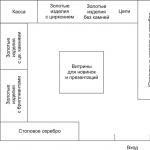 Placement and display of goods on the trading floor: rules and principles for the placement of goods Drawing up a layout for the placement of an assortment of goods of homogeneous groups
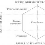 Communication strategy for brand promotion Communication brand idea
 Components of training - 稽古【Keiko】
 Role, style and way of consumption
 Customer and Contractor - relationships as the basis for the success of the project
 Encyclopedia of Marketing The main stages of marketing research