12 volt voltage indicator on LEDs. Voltage indicator, types, functions, instructions for use
In any technology, LEDs are used to display operating modes. The reasons are obvious - low cost, ultra-low power consumption, high reliability. Since the indicator circuits are very simple, there is no need to purchase factory-made products.
From the abundance of circuits for making a voltage indicator on LEDs with your own hands, you can choose the most optimal option. The indicator can be assembled in a couple of minutes from the most common radioelements.
All such circuits are divided into voltage indicators and current indicators according to their intended purpose.
Working with a 220V network
Let's consider the simplest option - phase checking.
This circuit is a current indicator light found on some screwdrivers. Such a device does not even require external power, since the potential difference between the phase wire and the air or hand is sufficient for the diode to glow.
To display the mains voltage, for example, to check the presence of current in the socket connector, the circuit is even simpler.

The simplest current indicator on 220V LEDs is assembled using capacitance to limit the current of the LED and a diode to protect against reverse half-wave.
DC Voltage Check
Often there is a need to ring the low-voltage circuit of household appliances, or check the integrity of a connection, for example, a wire from headphones.

As a current limiter, you can use a low-power incandescent lamp or a 50-100 Ohm resistor. Depending on the polarity of the connection, the corresponding diode lights up. This option is suitable for circuits up to 12V. For higher voltages, you will need to increase the limiting resistor.
Indicator for microcircuits (logic probe)

If there is a need to check the performance of a microcircuit, a simple probe with three stable states will help with this. If there is no signal (open circuit), the diodes do not light up. If there is a logical zero on the contact, a voltage of about 0.5 V appears, which opens transistor T1; if there is a logical one (about 2.4 V), transistor T2 opens.
This selectivity is achieved thanks to the different parameters of the transistors used. For KT315B the opening voltage is 0.4-0.5V, for KT203B it is 1V. If necessary, you can replace the transistors with others with similar parameters.
The device is an LED voltmeter (voltage indicator) of a 12V battery, using the well-known LM3914 microcircuit (datasheet).
I needed this device so that I knew when the car battery was fully charged from the charger. Because The charger was of an old type and did not have any dial or digital indicators for measuring voltage.
For the LED bar indicator, I chose an HDSP-4832 with 10 LEDs in three different colors: three red, four yellow and three green.
To correctly indicate voltage, you need to determine the lower and upper levels of the measured voltages, so that the first and last LEDs (strips) on the indicator light up, respectively, at these levels.
For a 12V car battery, the following ranges were selected: the first LED lit up at a voltage of 10V, and the last at a voltage of 13.5V, i.e. The voltage indication step was 0.35V per LED. Naturally, you can set other voltages using two trim resistors. This makes it possible to use this indicator to measure voltage, for example NiCd or NiMH batteries. The voltage limits in this case are set to V min = 0.9 * N cells and V max = 1.45 * N cells, where N cells is the number of battery “cans”. Plus, between the + and - batteries, a powerful resistor rated for a current of at least 0.5A must be placed to simulate a real load.
The LM3914 chip can operate in two modes: “dot” mode, in which only one LED lights up, and “bar” mode, in which several LEDs light up in increasing order. This circuit operates in “bar” mode; for this purpose, pin 9 of the microcircuit is connected to the positive of the power supply.
When operating in bar mode, the power consumption of the LM3914 increases accordingly. When all 10 LED segments are lit, the LM3914 consumes almost 10 times more than if only one LED (segment) was lit. To prevent burnout of the LM3914 m/s, it is necessary to ensure that the LED current does not exceed the maximum permissible.
The maximum power dissipation of the microcircuit should not exceed 1365 mW. And if we assume that the maximum input voltage is 14.4V, then the maximum possible current will be I = P/V = 1.365/14.4 = 94.8mA. That. the current of each indicator segment should not exceed 94.8/10=9.5mA. In the circuit, the resistance of resistor R3 (4.7 kOhm) sets the maximum current of the LEDs. The LED current is approximately 10 times greater than the current that passes through this resistor I R3 = 1.25 / 4700 = 266 μA. That. The current per LED is limited to 2.6 mA, which is much less than permissible.
Input stage: to take readings of the input voltage (and it also powers the circuit), the circuit uses a 1:2 voltage divider connected to pin 5 of the microcircuit. The divider consists of two resistors with a nominal value of 10 kOhm, etc. the voltage taken from the divider is in the range from 5V to 6.75V, while the input voltage will be from 10V to 13.5V. These same values will be used to calibrate the LM3914.
Schematic diagram of the indicator
The circuit consists of two elements: a separate control circuit and a separate indicator board. They are connected to each other using an 11-pin connector.
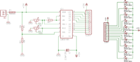
The main defining elements of the circuit:
R1 and R2 - voltage divider
R3 and R4 - limiting the LED current and setting the upper voltage limit
R5 - setting the lower voltage limit
I talked about R1, R2 and R3 above. Now let's look at R4, which sets the upper threshold (output 6 m/s):
At pins 6 and 7 of the microcircuit, it is necessary to set the voltage to 6.75V (which is the input voltage of 13.5V after the divider, if the battery is fully charged). Knowing the value of the current passing through R3, and also adding here the “error current” current from pin 8 of the microcircuit (120 μA), we can calculate the resistance of R4:
6.75V = 1.25V + R4(120uA+266uA)<=>
R4 = (6.75 - 1.25)/(386uA)<=>
R4 = 14.2 kOhm or more (we choose a 22 kOhm trimmer resistor)
With a 22 kOhm trimmer resistor, we can adjust the voltage on pin 7 in the range from 1.25V to 9.74V, which makes it possible to set the upper voltage limit from 2.5V to 19.5V.
Resistance R5 sets the lower voltage limit:
Substituting the following values into the formula V O = V I * R B /(R A + R B):
R A = 10 * 1K internal resistors LM3914
R B = R5
V I = upper voltage limit 6.75V
VO = lower voltage limit 5V
we get:
5 = 6.75 * R5/(R5 + 10K)
R5 = 28.5K or more (we choose a 100kOhm trim resistor)
Printed circuit board
As mentioned above, the device consists of two components; accordingly, 2 different printed circuit boards are used. This makes it possible to use a remote display, for example on a car panel.

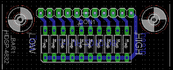
There was only one jumper on the printed circuit board (marked in red).

You can download the project in and printed circuit boards below
List of radioelements
| Designation | Type | Denomination | Quantity | Note | Shop | My notepad |
|---|---|---|---|---|---|---|
| IC1 | LED driver | LM3914 | 1 | To notepad | ||
| C1 | Electrolytic capacitor | 2.2 µF 25 V | 1 | To notepad | ||
| R1, R2 | Resistor | 10 kOhm | 2 | To notepad | ||
| R3 | Resistor | 4.7 kOhm | 1 | To notepad | ||
| R4 | Variable resistor | 22 kOhm | 1 | To notepad | ||
| R5 | Variable resistor | 100 kOhm | 1 | To notepad | ||
| BAR1 | Indicator | HDSP-4832 | 10 |
When carrying out even the most basic work with electricity, it is important to follow safety precautions. Even with extensive experience in this area, you should not take risks, as it is life-threatening. In order to check the presence of electric current, you must always have a voltage indicator on your household. The main advantage of this device is its ease of use and instant determination of the presence of current in the network.
If you look at the photo of the voltage indicator, you can see that this tool is a screwdriver with a built-in indicator.

Manufacturers offer many different types of indicators, but each has its own operating principle. Before use, you need to understand the rules and avoid mistakes.


Types of indicators
Screwdriver
The simplest and most common is a passive screwdriver indicator. With its help you can find out whether there is voltage in the circuit or not. The main advantage of this type of screwdriver is that the indicator shows the presence or absence of voltage after touching the contact.

There is a contact on the handle that must be clamped when we bring it to the conductor. The result of the current is shown by a neon lamp built into the handle.

Electricians rarely use this type of mains voltage indicator due to its low functionality. This type of indicator is more suitable for home use.

Active screwdriver
A more advanced indicator model is the active screwdriver. This type of screwdriver determines the presence of voltage in the network, as well as its integrity. The case contains a battery-powered circuit and an LED.

The main feature of this indicator is the possibility of contact and non-contact use, and is suitable for professional use.

Control
The most popular tester among electricians is a do-it-yourself voltage indicator - control. This is a design in the form of a light bulb inserted into a socket and wires, the edges of which are probes.

The control is convenient because it shows the presence of voltage and whether the power of the network is normal. The main advantage of this indicator is the ability to test three-phase circuits.

Multimeter
Another type of voltage indicator is a multimeter. This is a universal device that measures current, voltage, frequency, capacitance, etc. The multimeter measures to the nearest thousandths.


Universal probe
For professional use, electricians often choose a universal probe. This device is more multifunctional than the others. Thanks to the ability to determine phases, pros and cons, call, etc. This indicator is considered one of the main tools of an electrician.

Non-contact voltage indicator
A non-contact voltage indicator is also considered one of the safest. This type of indicator is equipped with three operating modes: non-contact use with high and low sensitivity and light notification. These three modes vary depending on the tasks being performed:
- Light notification - a signal is given by the glow of a light bulb. Detects the presence of current only upon contact.
- Non-contact notification with low sensitivity - the device detects the presence of current at a short distance.

Non-contact alert with high sensitivity – detects the presence of current over a long distance. This mode allows you to measure the voltage in wires plastered in the wall, as well as identify their route.

This screwdriver is a simplified multimeter. This is an excellent device with many functions and very easy to use. With its help, you can check the integrity of the circuit, determine the voltage at a distance, and also have light and sound indication.

To obtain more information about the electrical circuit, use a digital voltage indicator. This indicator on the display provides more detailed information by showing the digital value of the network voltage. With its help, you can control the voltage by setting maximum and minimum values. This device is installed to protect against voltage surges.


When choosing an indicator, it is important to know all the pros and cons. It is recommended to carry out work related to electricity with extreme caution, and check the presence of electricity in the network only using indicators.

Photo of voltage indicator


We also recommend
 A frozen miracle with your own hands: learning to make jewelry from epoxy resin DIY jewelry from epoxy resin
 How to make soda at home without much expense?
 Pedicab drawings dimensions
 We grow hops in the country How hops are harvested on an industrial scale
 How we build How we built the house ourselves
 Juicer. Types and device. Operation and application. How to choose. Centrifugal or auger juicer - what to choose How an old juicer works