Calculation of parallel connection of resistors calculator. How to calculate the resistance of resistors on a calculator
In practice, the problem of finding the resistance of conductors and resistors for various connection methods is often encountered. The article discusses how the resistance is calculated when the conductors are connected in parallel and some other technical issues.
Conductor resistance
All conductors have the property of preventing the flow of electric current, it is commonly called electrical resistance R, it is measured in ohms. This is the main property of conductive materials.
For conducting electrical calculations, specific resistance is used - ρ Ohm m / mm 2. All metals are good conductors, copper and aluminum are most widely used, and iron is used much less frequently. The best conductor is silver, it is used in the electrical and electronic industries. Alloys with high
When calculating the resistance, the formula known from the school physics course is used:
R = ρ · l/S, S - cross-sectional area; l - length.
If you take two conductors, then their resistance when connected in parallel will become less due to an increase in the total cross section.
and conductor heating
For practical calculations of the operating modes of conductors, the concept of current density is used - δ A / mm 2, it is calculated by the formula:
δ = I/S, I - current, S - section.
The current passing through the conductor heats it. The larger δ, the more the conductor heats up. For wires and cables, norms of permissible density have been developed, which are given in For conductors of heating devices, there are norms for current density.
If the density δ is higher than the permissible one, the conductor may be destroyed, for example, when the cable is overheated, its insulation is destroyed.
The rules regulate the calculation of conductors for heating.
Ways of connecting conductors
Any conductor is much more convenient to depict on the diagrams as an electrical resistance R, then they are easy to read and analyze. There are only three ways to connect resistances. The first way is the easiest - serial connection.
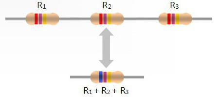
The photo shows that the total resistance is: R \u003d R 1 + R 2 + R 3.
The second way is more complicated - parallel connection. The calculation of resistance in parallel connection is carried out in stages. The total conductivity G = 1/R is calculated, and then the total resistance R = 1/G.

You can do it differently, first calculate the total resistance at R1 and R2, then repeat the operation and find R.
The third connection method is the most complex - a mixed connection, that is, all the considered options are present. The scheme is shown in the photo.

To calculate this circuit, it should be simplified; for this, resistors R2 and R3 are replaced with one R2.3. It turns out a simple scheme.
R2,3,4 = R2,3 R4/(R2,3 + R4).

The circuit becomes even simpler, it contains resistors that have a serial connection. In more complex situations, the same conversion method is used.
Types of conductors
In electronic engineering, during production, conductors are thin strips of copper foil. Due to their short length, their resistance is negligible, and in many cases it can be neglected. For these conductors, the resistance in parallel connection decreases due to the increase in cross section.
A large section of conductors is represented by winding wires. They are available in different diameters - from 0.02 to 5.6 mm. For powerful transformers and electric motors, rectangular copper bars are produced. Sometimes, during repairs, a large-diameter wire is replaced with several smaller ones connected in parallel.

A special section of conductors is represented by wires and cables, the industry provides the widest selection of grades for a variety of needs. Often you have to replace one cable with several, smaller sections. The reasons for this are very different, for example, a cable with a cross section of 240 mm 2 is very difficult to lay along a route with sharp bends. It is replaced with 2×120 mm 2 and the problem is solved.
Calculation of wires for heating
The conductor is heated by the flowing current, if its temperature exceeds the permissible value, the insulation is destroyed. PUE provides for the calculation of conductors for heating, the initial data for it are the current strength and the environmental conditions in which the conductor is laid. According to these data, the recommended conductor cross-section (wire or cable) is selected from the tables in the PUE.
In practice, there are situations when the load on the existing cable has greatly increased. There are two ways out - to replace the cable with another one, it can be expensive, or to lay another one parallel to it in order to relieve the main cable. In this case, the resistance of the conductor in parallel connection decreases, hence the heat generation decreases.
In order to correctly select the cross section of the second cable, they use the PUE tables, it is important not to make a mistake in determining its operating current. In this situation, the cooling of the cables will be even better than that of one. It is recommended to calculate the resistance for two cables in order to more accurately determine their heat dissipation.
Calculation of conductors for voltage loss
When the consumer R n is located at a large distance L from the energy source U 1, a rather large voltage drop occurs on the line wires. The consumer R n receives a voltage U 2 significantly lower than the initial U 1 . In practice, various electrical equipment connected to the line in parallel acts as a load.

To solve the problem, the resistance is calculated with the parallel connection of all equipment, so the load resistance R n is found. Next, determine the resistance of the line wires.
R l \u003d ρ 2L / S,
Here S is the cross section of the line wire, mm 2.
In every electrical circuit there is a resistor that has resistance to electric current. Resistors are of two types: fixed and variable. During the development of any electrical circuit and the repair of electronic products, it is often necessary to use a resistor with the required rating.
Although Resistors have different ratings, it may happen that it will not be possible to find the necessary one, or even no element at all can provide the required indicator.
The solution to this problem can be the use of serial and parallel connection. After reading this article, you will learn about the features of the calculation and selection of various resistance values.
Parallel connection: general information
 Often, in the manufacture of any device, resistors are used, which are connected in accordance with a serial circuit. The effect of using this assembly option is to increase the total resistance of the circuit. For this option of connecting the elements, the resistance they create is calculated as the sum of the ratings. If the assembly of parts is carried out according to a parallel scheme, then here need to calculate the resistance using the formulas below.
The parallel connection scheme is used in situations where the task is to reduce the total resistance, and, in addition, increase the power for a group of elements connected in parallel, which should be greater than when they are connected separately.
Resistance calculation
 In the case of connecting parts to each other, using a parallel circuit to calculate the total resistance, the following formula will be used:
R(gen)=1/(1/R1+1/R2+1/R3+1/Rn).
- R1-R3 and Rn are resistors connected in parallel.
 Moreover, if the circuit is created on the basis of only two elements, then the following formula should be used to determine the total nominal resistance:
R(total)=R1*R2/R1+R2.
- R(gen) - total resistance;
- R1 and R2 are resistors connected in parallel.
Video: Resistance Calculation Example
Universal calculation scheme With regard to radio engineering, attention should be paid to one important rule: if the elements connected to each other in a parallel circuit have the same score, then to calculate the total nominal value, it is necessary to divide the total value by the number of connected nodes:
- R(total) - the total value of the resistance;
- R is the value of the resistor connected in parallel;
- n is the number of connected nodes.
Particular attention should be paid to the fact that the final resistance in the case of using a parallel connection will definitely be less compared to the rating of any element connected to the circuit.
Calculation example
 For greater clarity, consider the following example: let's say we have three resistors, whose values are respectively 100, 150 and 30 ohms. If we use the first formula to determine the total face value, we get the following:
R(total)=1/(1/100+1/150+1/30)=
1 / (0.01 + 0.007 + 0.03) \u003d 1 / 0.047 \u003d 21.28 Ohm.
If you perform simple calculations, you can get the following: for a circuit that includes three parts, where the lowest resistance is 30 ohms, the resulting nominal value will be 21.28 ohms. This indicator will be less than the minimum value of the nominal value in the circuit by almost 30%.
Important nuances
 Usually, for resistors, parallel connection is used when the task is to create a resistance of greater power. To solve it, resistors will be required, which should have equal resistance and power indicators. With this option you can determine the total power as follows: the power of one element must be multiplied with the total number of all the resistors that make up the circuit, connected to each other in accordance with the parallel circuit.
Let's say if we use five resistors, whose nominal value is 100 ohms, and the power of each is 1 W, which are connected to each other in accordance with a parallel circuit, then the total resistance will be 20 ohms, and the power will be 5 watts.
If we take the same resistors, but connect them in accordance with the serial circuit, then the final power will be 5 W, and the total value will be 500 ohms.
Video: Correct connection of LEDs
The parallel circuit for connecting resistors is in great demand for the reason that the task often arises of creating such a rating that cannot be achieved using a simple parallel connection. Wherein the procedure for calculating this parameter is rather complicated where different parameters must be taken into account.
Here, an important role is played not only by the number of connected elements, but also by the operating parameters of the resistors - first of all, resistance and power. If one of the connected elements has an unsuitable indicator, then this will not effectively solve the problem of creating the required denomination in the circuit.
), today we will talk about possible ways to connect resistors, in particular about serial connection and about parallel.
Let's start by looking at a circuit whose elements are connected. successively. And although we will consider only resistors as circuit elements in this article, the rules regarding voltages and currents for different connections will be valid for other elements. So, the first circuit that we will disassemble looks like this:

Here we have a classic case serial connection- two resistors connected in series. But let's not get ahead of ourselves and calculate the total resistance of the circuit, but first we will consider all voltages and currents. So, the first rule is that the currents flowing through all conductors in a series connection are equal to each other:
And to determine the total voltage in a series connection, the voltages on individual elements must be summed up:
At the same time, for voltages, resistances and currents in this circuit, the following relations are valid:
Then the following expression can be used to calculate the total voltage:
But for the total voltage, Ohm's law also holds:
Here, is the total resistance of the circuit, which, based on two formulas for the total voltage, is equal to:
Thus, when resistors are connected in series, the total resistance of the circuit will be equal to the sum of the resistances of all conductors.
For example for the following chain:

The total resistance will be:
The number of elements does not matter, the rule by which we determine the total resistance will work in any case 🙂 And if all the resistances are equal in series connection (), then the total resistance of the circuit will be:
In this formula, it is equal to the number of elements in the chain.
We figured out the series connection of resistors, let's move on to parallel.

With a parallel connection, the voltages on the conductors are equal:
And for currents, the following expression is true:
That is, the total current branches into two components, and its value is equal to the sum of all components. Ohm's law:


Substitute these expressions in the formula for the total current:
And according to Ohm's law, the current:
Equate these expressions and get the formula for the total resistance of the circuit:

This formula can be written in a slightly different way:
Thus,when the conductors are connected in parallel, the reciprocal of the total resistance of the circuit is equal to the sum of the reciprocals of the resistances of the parallel-connected conductors.
A similar situation will be observed with a larger number of conductors connected in parallel:

In addition to parallel and series connections of resistors, there is also mixed connection. From the name it is already clear that with such a connection in the circuit there are resistors connected both in parallel and in series. Here is an example of such a circuit:

Let's calculate the total resistance of the circuit. Let's start with resistors and - they are connected in parallel. We can calculate the total resistance for these resistors and replace them in the circuit with a single resistor:

Everyone in this life has come across resistors. People with humanitarian professions, like everyone else, studied conductors of electric current and Ohm's law at school in physics lessons.
Students of technical universities and engineers of various manufacturing enterprises also deal with resistors. All these people, one way or another, faced the task of calculating the electrical circuit for various types of connection of resistors. This article will focus on the calculation of physical parameters that characterize the circuit.
Connection types
Resistor - passive element present in every electrical circuit. It is designed to resist electrical current. There are two types of resistors:
- Permanent.
- Variables.
Why solder conductors to each other? For example, if a certain electrical circuit needs a certain resistance. And among the nominal indicators, there is no need. In this case, it is necessary to select circuit elements with certain resistance values and connect them. Depending on the type of connection and the resistance of the passive elements, we will get some specific circuit resistance. It is called equivalent. Its value depends on the type of soldering of conductors. Exists three types of conductor connections:
- Sequential.
- Parallel.
- Mixed.
The value of the equivalent resistance in the circuit is considered quite easily. However, if there are a lot of resistors in the circuit, then it is better to use a special calculator that calculates this value. When doing the calculation manually, in order to avoid mistakes, you need to check whether you have taken the right formula.
Serial connection of conductors
 In a series soldering, the resistors go as if one after another. The value of the equivalent circuit resistance is equal to the sum of the resistances of all resistors. The peculiarity of schemes with such soldering is that current value constant. According to Ohm's law, the voltage in a circuit is equal to the product of current and resistance. Since the current is constant, to calculate the voltage across each resistor, it is enough to multiply the values. After that, it is necessary to add the voltages of all resistors, and then we will get the voltage value in the entire circuit.
The calculation is very simple. Since it is mainly development engineers who deal with it, it will not be difficult for them to calculate everything manually. But if there are a lot of resistors, then it is easier to use a special calculator.
An example of a serial connection of conductors in everyday life is a Christmas tree garland.
Parallel connection of resistors
With parallel connection of conductors the equivalent resistance in the circuit is calculated differently. A little more difficult than with sequential.
Its value in such circuits is equal to the product of the resistances of all resistors, divided by their sum. There are also other variations of this formula. Parallel connection of resistors always reduces the equivalent circuit resistance. That is, its value will always be less than the largest value of any of the conductors.
In such schemes voltage value constant. That is, the voltage value in the entire circuit is equal to the voltage values of each of the conductors. It is set by the voltage source.
The current in a circuit is equal to the sum of all the currents flowing through all the conductors. The value of the current flowing through the conductor. is equal to the ratio of the source voltage to the resistance of this conductor.
Examples of parallel connection of conductors:
- Lighting.
- Sockets in the apartment.
- Production equipment.
To calculate circuits with parallel connection of conductors, it is better to use a special calculator. If the circuit has a lot of resistors soldered in parallel, then you can calculate the equivalent resistance much faster with this calculator.
Mixed connection of conductors
 This type of connection consists of cascades of resistors. For example, we have a cascade of 10 conductors connected in series, followed by a cascade of 10 conductors connected in parallel. The equivalent resistance of this circuit will be equal to the sum of the equivalent resistances of these stages. That is, in fact, here is a serial connection of two cascades of conductors.
Many engineers are engaged in the optimization of various circuits. Its purpose is to reduce the number of elements in the circuit by selecting others with suitable resistance values. Complex schemes are divided into several small cascades, because it is much easier to do calculations.
Now, in the twenty-first century, it has become much easier for engineers to work. After all, a few decades ago, all calculations were made manually. And now programmers have developed special calculator to calculate the equivalent circuit resistance. It contains formulas that are used for calculations.
In this calculator, you can select the type of connection, and then enter the resistance values \u200b\u200binto special fields. After a few seconds, you will already see this value.
Parallel connection of resistors- one of two types of electrical connections, when both terminals of one resistor are connected to the corresponding terminals of another resistor or resistors. Often or in parallel in order to create more complex electronic circuits.
The parallel connection diagram is shown in the figure below. When resistors are connected in parallel, the voltage across all resistors will be the same, and the current flowing through them will be proportional to their resistance:
Resistors Parallel Formula
The total resistance of several resistors connected in parallel is given by the following formula:

The current flowing through a single resistor, according to, can be found by the formula:

Parallel connection of resistors - calculation
Example #1
When developing the device, it became necessary to install a resistor with a resistance of 8 ohms. If we look at the entire nominal range of standard resistor values, we will see that there is no resistor with a resistance of 8 ohms.
The way out of this situation is to use two resistors connected in parallel. The equivalent resistance value for two resistors connected in parallel is calculated as follows:

This equation shows that if R1 is equal to R2, then R is half the resistance of one of the two resistors. With R = 8 ohms, R1 and R2 should therefore be 2 × 8 = 16 ohms.
Now let's check by calculating the total resistance of the two resistors:

Thus, we obtained the required resistance of 8 ohms by connecting two 16 ohm resistors in parallel.
Calculation example No. 2
Find the total resistance R of three resistors connected in parallel:

The total resistance R is calculated by the formula:

This calculation method can be used to calculate any number of individual resistances connected in parallel.
One important point to remember when calculating resistors connected in parallel is that the total resistance will always be less than the value of the lowest resistance in that combination.
How to calculate complex resistor connections
More complex resistor connections can be calculated by grouping resistors systematically. In the figure below, you need to calculate the total resistance of a circuit consisting of three resistors:

For ease of calculation, we first group the resistors by parallel and series connection type.
Resistors R2 and R3 are connected in series (group 2). They, in turn, are connected in parallel with the resistor R1 (group 1).
The series connection of group 2 resistors is calculated as the sum of the resistances R2 and R3:

As a result, we simplify the circuit in the form of two parallel resistors. Now the total resistance of the entire circuit can be calculated as follows:

The calculation of more complex resistor connections can be performed using Kirchhoff's laws.
Current flowing in a circuit of resistors connected in parallel
The total current I flowing in a circuit of parallel resistors is equal to the sum of the individual currents flowing in all parallel branches, and the current in a single branch does not have to be equal to the current in neighboring branches.
Despite the parallel connection, the same voltage is applied to each resistor. And since the value of resistance in a parallel circuit can be different, then the amount of current flowing through each resistor will also be different (by the definition of Ohm's law).
Consider this using the example of two resistors connected in parallel. The current that flows through each of the resistors (I1 and I2) will be different from each other because the resistances of the resistors R1 and R2 are not equal.
However, we know that the current that enters the circuit at point "A" must leave the circuit at point "B".

Kirchhoff's first rule states: "The total current leaving the circuit is equal to the current entering the circuit."
Thus, the total current flowing in the circuit can be defined as:
Then, using Ohm's law, you can calculate the current that flows through each resistor:
Current flowing in R1 = U ÷ R1 = 12 ÷ 22 kΩ = 0.545 mA
Current flowing in R 2 \u003d U ÷ R2 \u003d 12 ÷ 47 kOhm \u003d 0.255 mA
So the total current will be:
I = 0.545 mA + 0.255 mA = 0.8 mA
This can also be verified using Ohm's law:
I = U ÷ R = 12 V ÷ 15 kΩ = 0.8 mA (same)
where 15 kΩ is the total resistance of two resistors connected in parallel (22 kΩ and 47 kΩ)
And in conclusion, I would like to note that most modern resistors are marked with colored stripes and you can find out its purpose.
Parallel Connection of Resistors - Online Calculator
To quickly calculate the total resistance of two or more resistors connected in parallel, you can use the following online calculator:
Summarize
When two or more resistors are connected so that both terminals of one resistor are connected to the corresponding terminals of the other resistor or resistors, they are said to be connected in parallel. The voltage across each resistor within a parallel combination is the same, but the currents flowing through them may differ from each other, depending on the value of the resistances of each resistor.
The equivalent or impedance of a parallel combination will always be less than the minimum resistance of the resistor included in the parallel connection.
We also recommend
 Optimal blades for a wind generator: type, shape, materials and DIY instructions
 We build a HF antenna a guide for beginner radio amateurs
 Domestic microwave transistors
 Homemade spot welding Simple timer for spot welding
 Homemade soldering stations
 Motion sensor on MK PIC and PIR sensor Infrared motion sensor arduino