Operating principle and connection diagram of a fluorescent lamp. Connection diagrams for fluorescent fluorescent lamps How to light a burnt out fluorescent lamp diagram
When choosing a modern method of lighting a room, you need to know how to connect a fluorescent lamp yourself.
The large surface area of the glow helps to obtain even and diffuse illumination.
Therefore, this option has become very popular and in demand in recent years.
Fluorescent lamps belong to gas-discharge lighting sources, characterized by the formation of ultraviolet radiation under the influence of an electrical discharge in mercury vapor with subsequent conversion into high visible light output.
The appearance of light is due to the presence on the inner surface of the lamp of a special substance called phosphor, which absorbs UV radiation. Changing the composition of the phosphor allows you to change the tint range of the glow. The phosphor can be represented by calcium halophosphates and calcium-zinc orthophosphates.

The principle of operation of a fluorescent light bulb
The arc discharge is supported by thermionic emission of electrons on the surface of the cathodes, which are heated by passing a current limited by the ballast.
The disadvantage of fluorescent lamps is represented by the inability to make a direct connection to the electrical network, which is due to the physical nature of the lamp glow.
A significant part of luminaires intended for installation of fluorescent lamps have built-in glow mechanisms or chokes.
Connecting a fluorescent lamp
 To correctly carry out independent connection, you need to choose the right fluorescent lamp.
Such products are marked with a three-digit code containing all the information about the quality of light or color rendering index and color temperature.
The first number of the marking indicates the level of color rendering, and the higher these indicators are, the more reliable color rendering can be obtained during the lighting process.
The designation of the lamp glow temperature is represented by digital indicators of the second and third order.
The most widely used is an economical and highly efficient connection based on an electromagnetic ballast, supplemented by a neon starter, as well as a circuit with a standard electronic ballast.
Connection diagrams for a fluorescent lamp with a starter
Connecting an incandescent lamp yourself is quite simple, due to the presence of all the necessary elements and a standard assembly diagram in the kit.
Two tubes and two chokes
 The technology and features of independent serial connection in this way are as follows:
- supply of phase wire to the ballast input;
- connecting the choke output to the first contact group of the lamp;
- connecting the second contact group to the first starter;
- connection from the first starter to the second lamp contact group;
- connecting the free contact to the wire to zero.
The second tube is connected in a similar way. The ballast is connected to the first lamp contact, after which the second contact from this group goes to the second starter. Then the starter output is connected to the second lamp pair of contacts and the free contact group is connected to the neutral input wire.
This connection method, according to experts, is optimal if there are a pair of lighting sources and a pair of connecting kits.
Connection diagram for two lamps from one choke
Independent connection from one choke is a less common, but completely uncomplicated option. This two-lamp series connection is economical and requires the purchase of an induction choke, as well as a pair of starters:
- a starter is connected to the lamps through a parallel connection to the pin output at the ends;
- sequential connection of free contacts to the electrical network using a choke;
- connecting capacitors in parallel to the contact group of the lighting device.

Two lamps and one choke
Standard switches belonging to the category of budget models are often characterized by sticking contacts as a result of increased starting currents, so it is advisable to use special high-quality versions of contact switching devices.
How to connect a fluorescent lamp without a choke?
Let's look at how fluorescent fluorescent lamps are connected. The simplest chokeless connection scheme is used even on burnt-out fluorescent lamp tubes and is distinguished by the absence of the use of an incandescent filament.
In this case, the power supply to the lighting device tube is due to the presence of an increased DC voltage through a diode bridge.

Switching on a lamp without a choke
This circuit is characterized by the presence of a conductive wire or a wide strip of foil paper, one side connected to the terminal of the lamp electrodes. For fixation at the ends of the bulb, metal clamps of the same diameter as the lamp are used.
Electronic ballast
The operating principle of a lighting fixture with electronic ballast is that electric current passes through a rectifier and then enters the buffer zone of the capacitor.
In electronic ballast, along with classic starting control devices, starting and stabilization occurs through a throttle. Power depends on high frequency current.

Electronic ballast
The natural complexity of the circuit is accompanied by a number of advantages compared to the low-frequency version:
- increasing efficiency indicators;
- elimination of flickering effect;
- reduction in weight and dimensions;
- absence of noise during operation;
- increasing reliability;
- long service life.
In any case, one should take into account the fact that electronic ballasts belong to the category of pulsed devices, so turning them on without sufficient load is the main cause of failure.
Checking the performance of an energy-saving lamp
Simple testing allows you to timely identify a breakdown and correctly determine the main cause of the malfunction, and sometimes even perform the simplest repair work yourself:

- Dismantling the diffuser and carefully examining the fluorescent tube in order to detect areas of pronounced blackening. Very rapid blackening of the ends of the flask indicates burnout of the spiral.
- Checking the filaments for breaks using a standard multimeter. If there is no damage to the threads, the resistance values can vary within 9.5-9.2Om.
If checking the lamp does not show malfunctions, then the lack of operation may be due to the breakdown of additional elements, including the electronic ballast and the contact group, which quite often undergoes oxidation and needs to be cleaned.
Checking the performance of the throttle is carried out by disconnecting the starter and shorting it to the cartridge. After this, you need to short-circuit the lamp sockets and measure the throttle resistance. If replacing the starter fails to achieve the desired result, then the main fault, as a rule, lies in the capacitor.
What causes danger in an energy-saving lamp?
Various energy-saving lighting devices, which have recently become very popular and fashionable, according to some scientists, can cause quite serious harm not only to the environment, but also to human health:- poisoning with mercury-containing vapors;
- lesions of the skin with the formation of a severe allergic reaction;
- increased risk of developing malignant tumors.
Flickering lamps often cause insomnia, chronic fatigue, decreased immunity and the development of neurotic conditions.
It is important to know that mercury is released from a broken fluorescent lamp bulb, so operation and further disposal must be carried out in compliance with all rules and precautions.
A significant reduction in the service life of a fluorescent lamp, as a rule, is caused by voltage instability or malfunctions of the ballast resistance, therefore, if the electrical network is of insufficient quality, it is suggested to use conventional incandescent lamps.
Video on the topic
Fluorescent lamps (FLLs) are widely used to illuminate both large areas of public premises and as household light sources. The popularity of fluorescent lamps is largely due to their economic characteristics. Compared to incandescent lamps, this type of lamp has high efficiency, increased light output and a longer service life. However, a functional disadvantage of fluorescent lamps is the need for a starting starter or a special ballast (ballast). Accordingly, the task of starting the lamp when the starter fails or is absent is urgent and relevant.
The fundamental difference between an LDS and an incandescent lamp is that the conversion of electricity into light occurs due to the flow of current through mercury vapor mixed with an inert gas in a bulb. Current begins to flow after breakdown of the gas by high voltage applied to the electrodes of the lamp.
- Throttle.
- Lamp bulb.
- Luminescent layer.
- Starter contacts.
- Starter electrodes.
- Starter housing.
- Bimetallic plate.
- Lamp filaments.
- Ultraviolet radiation.
- Discharge current.
The resulting ultraviolet radiation lies in the part of the spectrum invisible to the human eye. To convert it into a visible light flux, the walls of the bulb are coated with a special layer, a phosphor. By changing the composition of this layer, you can obtain different light shades.
Before the direct launch of the LDS, the electrodes at its ends are heated by passing a current through them or due to the energy of a glow discharge.
High breakdown voltage is provided by ballasts, which can be assembled according to a well-known traditional circuit or have a more complex design.
Starter operating principle
In Fig. Figure 1 shows a typical connection of an LDS with a starter S and a choke L. K1, K2 – lamp electrodes; C1 is a cosine capacitor, C2 is a filter capacitor. A mandatory element of such circuits is a choke (inductor) and a starter (chopper). The latter is often used as a neon lamp with bimetallic plates. To improve the low power factor due to the presence of inductor inductance, an input capacitor is used (C1 in Fig. 1).
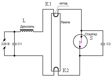
Rice. 1 Functional diagram of LDS connection
The LDS startup phases are as follows:
1) Warming up the lamp electrodes. In this phase, the current flows through the circuit “Network – L – K1 – S – K2 – Network”. In this mode, the starter begins to close/open randomly.
2) At the moment the circuit is broken by the starter S, the magnetic field energy accumulated in the inductor L is applied in the form of high voltage to the electrodes of the lamp. An electrical breakdown of the gas inside the lamp occurs.
3) In breakdown mode, the lamp resistance is lower than the resistance of the starter branch. Therefore, the current flows along the circuit “Network – L – K1 – K2 – Network”. In this phase, inductor L acts as a current-limiting reactor.
Disadvantages of the traditional LDS starting circuit: acoustic noise, flickering with a frequency of 100 Hz, increased start-up time, low efficiency.
Operating principle of electronic ballasts
Electronic ballasts (EPG) use the potential of modern power electronics and are more complex, but also more functional circuits. Such devices allow you to control the three startup phases and adjust the light output. The result is longer lamp life. Also, due to the lamp being powered with a current of a higher frequency (20÷100 kHz), there is no visible flicker. A simplified diagram of one of the popular electronic ballast topologies is shown in Fig. 2.

Rice. 2 Simplified circuit diagram of electronic ballasts
In Fig. 2 D1-D4 – mains voltage rectifier, C – filter capacitor, T1-T4 – transistor bridge inverter with transformer Tr. Optionally, the electronic ballast may contain an input filter, a power factor correction circuit, additional resonant chokes and capacitors.
A complete schematic diagram of one of the typical modern electronic ballasts is shown in Fig. 3.

Rice. 3 Diagram of BIGLUZ electronic ballasts
The circuit (Fig. 3) contains the main elements mentioned above: a bridge diode rectifier, a filter capacitor in the DC link (C4), an inverter in the form of two transistors with wiring (Q1, R5, R1) and (Q2, R2, R3), inductor L1, transformer with three terminals TR1, trigger circuit and lamp resonant circuit. Two windings of the transformer are used to turn on transistors, the third winding is part of the resonant circuit of the LDS.
Methods for starting LDS without specialized ballasts
When a fluorescent lamp fails, there are two possible reasons:
1) . In this case, it is enough to replace the starter. The same operation should be carried out if the lamp flickers. In this case, upon visual inspection, there are no characteristic darkening on the LDS flask.
2) . Perhaps one of the electrode threads has burned out. Upon visual inspection, darkening may be noticeable at the ends of the bulb. Here you can use known starting circuits to continue operating the lamp even with burnt-out electrode threads.
For emergency starting, a fluorescent lamp can be connected without a starter according to the diagram below (Fig. 4). Here the user plays the role of starter. Contact S1 is closed for the entire period of lamp operation. Button S2 is closed for 1-2 seconds to light the lamp. When S2 opens, the voltage on it at the moment of ignition will be significantly higher than the mains voltage! Therefore, extreme caution should be exercised when working with such a scheme.

Rice. 4 Schematic diagram of starting an LDS without a starter
If you need to quickly ignite an LVDS with burnt filaments, then you need to assemble a circuit (Fig. 5).

Rice. 5 Schematic diagram of connecting an LDS with a burnt filament
For a 7-11 W inductor and a 20 W lamp, the C1 rating is 1 µF with a voltage of 630 V. Capacitors with a lower rating should not be used.
Automatic circuits for starting an LDS without a choke involve using an ordinary incandescent lamp as a current limiter. Such circuits, as a rule, are multipliers and supply the LDS with direct current, which causes accelerated wear of one of the electrodes. However, we emphasize that such circuits allow you to run even an LDS with burnt-out electrode threads for some time. A typical connection diagram for a fluorescent lamp without a choke is shown in Fig. 6.

Rice. 6. Block diagram of connecting an LDS without a choke

Rice. 7 Voltage on the LDS connected according to the diagram (Fig. 6) before start-up
As we see in Fig. 7, the voltage on the lamp at the moment of starting reaches the level of 700 V in approximately 25 ms. Instead of an HL1 incandescent lamp, you can use a choke. Capacitors in the diagram of Fig. 6 should be selected within 1÷20 µF with a voltage of at least 1000V. Diodes must be designed for a reverse voltage of 1000V and a current of 0.5 to 10 A, depending on the lamp power. For a 40 W lamp, diodes rated for current 1 will be sufficient.
Another version of the launch scheme is shown in Fig. 8.

Rice. 8 Schematic diagram of a multiplier with two diodes
Parameters of capacitors and diodes in the circuit in Fig. 8 are similar to the diagram in Fig. 6.
One of the options for using a low-voltage power supply is shown in Fig. 9. Based on this circuit (Fig. 9), you can assemble a wireless fluorescent lamp on a battery.

Rice. 9 Schematic diagram of connecting LDS from a low-voltage power source
For the above circuit, it is necessary to wind a transformer with three windings on one core (ring). As a rule, the primary winding is wound first, then the main secondary (indicated as III in the diagram). Cooling must be provided for the transistor.
Conclusion
If the fluorescent lamp starter fails, you can use an emergency “manual” start or simple DC power circuits. When using circuits based on voltage multipliers, it is possible to start a lamp without a choke using an incandescent lamp. When operating on direct current, there is no flicker or noise from the LDS, but the service life is reduced.
If one or two filaments of the cathodes of a fluorescent lamp burn out, it can continue to be used for some time, using the above-mentioned circuits with increased voltage.
The fluorescent lamp was invented in the 1930s as a light source and became famous and widespread in the late 1950s.
Its advantages are undeniable:
- Durability.
- Maintainability
- Economical.
- Warm, cold and colored shade of glow.
A long service life is ensured by a properly designed start-up and operation control device by the developers.
Industrial fluorescent lampLDS (fluorescent lamp) is much more economical than a conventional incandescent light bulb, however, an LED device of similar power is superior to a fluorescent one in this indicator.
Over time, the lamp stops starting, blinks, “buzzes”, in a word, does not return to normal mode. Staying and working indoors becomes dangerous to a person’s vision.
To correct the situation, they try to turn on a known good LDS.
If a simple replacement does not produce positive results, a person who does not know how a fluorescent lamp works comes to a dead end: “What to do next?” We will look at what spare parts to buy in the article.
Briefly about the features of the lamp
LDS refers to gas-discharge light sources of low internal pressure.
The operating principle is as follows: the sealed glass case of the device is filled with inert gas and mercury vapor, the pressure of which is low. The inner walls of the flask are coated with phosphor. Under the influence of an electrical discharge occurring between the electrodes, the mercury composition of the gas begins to glow, generating ultraviolet radiation invisible to the eye. It, having an effect on the phosphor, causes a glow in the visible range. By changing the active composition of the phosphor, cold or warm white and colored light is obtained.
 Operating principle of LDS
Expert opinion
Alexey Bartosh
Ask a question to an expertBactericidal devices are designed in the same way as LDS, but the inner surface of the flask, made of quartz sand, is not coated with a phosphor. Ultraviolet light is emitted unhindered into the surrounding space.
Connection using electromagnetic ballast or electronic ballast
The structural features do not allow connecting the LDS directly to a 220 V network - operation from this voltage level is impossible. To start, a voltage of at least 600V is required.
Using electronic circuits, it is necessary to provide the required operating modes one after another, each of which requires a certain voltage level.
Operating modes:
- ignition;
- glow.
Triggering involves applying high voltage pulses (up to 1 kV) to the electrodes, causing a discharge to occur between them.
Certain types of ballasts, before starting, heat the spiral of electrodes. Incandescence makes it easier to start the discharge, while the filament overheats less and lasts longer.
After the lamp lights up, power is supplied by alternating voltage, and the energy-saving mode is activated.
 Connection using electronic ballasts
  connection diagram
 In devices produced by industry, two types of ballasts (ballasts) are used:
- electromagnetic ballast control device EmPRA;
- electronic ballast - electronic ballast.
The diagrams provide for various connections, they are presented below.
Scheme with electronic ballasts
 Connection using electronic ballasts
 The electrical circuit of a luminaire with electromagnetic ballasts (EMP) includes the following elements:
- throttle;
- starter;
- compensation capacitor;
- Fluorescent Lamp.
 connection diagram
 When power is supplied through the circuit: throttle – LDS electrodes, voltage appears at the starter contacts.
The bimetallic contacts of the starter, located in a gaseous environment, heat up and close. Because of this, a closed circuit is created in the lamp circuit: 220 V contact – choke – starter electrodes – lamp electrodes – 220 V contact.
The electrode threads, when heated, emit electrons, which create a glow discharge. Part of the current begins to flow through the circuit: 220V – choke – 1st electrode – 2nd electrode – 220V. The current in the starter drops, the bimetallic contacts open. According to the laws of physics, at this moment a self-induction EMF appears at the inductor contacts, which leads to the appearance of a high-voltage pulse at the electrodes. A breakdown of the gaseous medium occurs, and an electric arc occurs between opposite electrodes. The LDS begins to glow with an even light.
Subsequently, a choke connected in line ensures a low level of current flowing through the electrodes.
A choke connected to an alternating current circuit acts as an inductive reactance, reducing the efficiency of the lamp by up to 30%.
Attention! In order to reduce energy losses, a compensating capacitor is included in the circuit; without it, the lamp will work, but power consumption will increase.
Circuit with electronic ballasts
Attention! In retail, electronic ballasts are often found under the name electronic ballast. Sellers use the name driver to designate power supplies for LED strips.
 Appearance and design of electronic ballasts
 Appearance and design of an electronic ballast designed to turn on two lamps with a power of 36 watts each.
Expert opinion
Alexey Bartosh
Specialist in repair and maintenance of electrical equipment and industrial electronics.
Ask a question to an expertImportant! It is forbidden to turn on electronic ballasts without a load in the form of fluorescent lamps. If the device is designed to connect two LDS, it cannot be used in a circuit with one.
In circuits with electronic ballasts, the physical processes remain the same. Some models provide pre-heating of the electrodes, which increases the life of the lamp.
 Electronic ballast type
 The figure shows the appearance of electronic ballasts for devices of different power levels.
The dimensions allow the electronic ballast to be placed even in an E27 base.
 Electronic ballasts in the base of an energy-saving lamp
 Compact ESLs - one of the types of fluorescent ones - can have a g23 base.
 Table lamp with G23 base
  Functional diagram of electronic ballasts
 The figure shows a simplified functional diagram of electronic ballasts.
Circuit for connecting two lamps in series
There are lamps that are designed to connect two lamps.
In case of replacement of parts, assembly is carried out according to schemes that are different for electronic ballasts and electronic ballasts.
Attention! Schematic diagrams of ballasts are designed to operate with a certain load power. This indicator is always available in product passports. If you connect lamps of a higher rating, the inductor or ballast may burn out.
 Connection diagram for two lamps with one choke
 If the device body has the inscription 2X18, the ballast is designed to connect two lamps with a power of 18 watts each. 1X36 - such a choke or ballast is capable of turning on one LDS with a power of 36 W.
In cases where a choke is used, the lamps must be connected in series.
Two starters will start their glow. These parts are connected in parallel with the LDS.
Connection without starter
The electronic ballast circuit does not initially include a starter.
 Button instead of starter
 However, in circuits with a choke you can do without it. A spring-loaded switch connected in series - in other words, a button - will help you assemble a working circuit. Briefly turning on and releasing the button will provide a connection similar in effect to the starter.
Important! This starterless option will turn on only with intact filaments.
The throttleless option, which also lacks a starter, can be implemented in different ways. One of them is shown below.
 Luminescent What to do if a fluorescent lamp breaks
Widely used fluorescent lamps are not without drawbacks: during their operation, the buzzing of the choke can be heard, the power system has a starter that is unreliable in operation, and most importantly, the lamp has a filament that can burn out, which is why the lamp has to be replaced with a new one.
The fluorescent lamp becomes “eternal”
Shown here is a diagram that eliminates these shortcomings. There is no usual buzzing, the lamp lights up instantly, there is no unreliable starter, and, most importantly, you can use a lamp with a burnt-out filament. 
Capacitors C1, C4 must be paper, with an operating voltage of 1.5 times the supply voltage. It is advisable for capacitors C2, C3 to be mica.
Resistor R1 is necessarily a wire-wound one; its resistance depends on the power of the lamp.
Data for circuit elements depending on the power of fluorescent lamps are given in the table:
Diodes D2, D3 and capacitors C1, C4 represent a full-wave rectifier with doubling the voltage. The values of capacitances C1, C4 determine the operating voltage of lamp L1 (the larger the capacitance, the greater the voltage on the electrodes of lamp L1). At the moment of switching on, the voltage at points a and b reaches 600 V, which is applied to the electrodes of lamp L1. At the moment of ignition of lamp L1, the voltage at points a and b decreases and ensures normal operation of lamp L1, designed for a voltage of 220 V.
The use of diodes D1, D4 and capacitors C2, C3 increases the voltage to 900 V, which ensures reliable ignition of lamp L1 at the moment of switching on. Capacitors C2, C3 simultaneously help suppress radio interference.
Lamp L1 can work without D1, D4, C2, C3, but in this case the reliability of inclusion decreases.

Recently I looked at a whole box of burnt-out energy-saving lamps, mostly with good electronics, but burnt-out fluorescent lamp filaments, and I thought - I need to use all this stuff somewhere. As you know, LDS with burnt filaments must be powered with rectified mains current using a starterless starting device. In this case, the filaments of the lamp are bridged by a jumper and a high voltage is applied to it to turn on the lamp. There is an instantaneous cold ignition of the lamp, with a sharp increase in voltage across it, upon start-up without preheating the electrodes.
And although ignition with cold electrodes is a more difficult mode than ignition in the usual way, this method allows you to use a fluorescent lamp for lighting for a long time. As you know, igniting a lamp with cold electrodes requires increased voltage up to 400...600 V. This is realized by a simple rectifier, the output voltage of which will be almost twice as high as the input network 220V. An ordinary low-power incandescent light bulb is installed as a ballast, and although using a lamp instead of a choke reduces the efficiency of such a lamp, if we use incandescent lamps with a voltage of 127 V and connect it to the DC circuit in series with the lamp, we will have sufficient brightness.

Any rectifier diodes, for voltage from 400V and current 1A, you can also use Soviet brown KTs-shki. Capacitors also have an operating voltage of at least 400V.

This device works as a voltage doubler, the output voltage of which is applied to the cathode - the anode of the LDS. After the lamp is ignited, the device switches to full-wave rectification mode with an active load and the voltage is equally distributed between lamps EL1 and EL2, which is true for LDS with a power of 30 - 80 W, having an operating voltage on average of about 100 V. With this connection of the circuit, the luminous flux incandescent lamps will be approximately a quarter of the LDS flux.

A 40 W fluorescent lamp requires a 60 W, 127 V incandescent lamp. Its luminous flux will be 20% of the LDS flux. And for an LDS with a power of 30 W, you can use two 127 V incandescent lamps of 25 W each, connecting them in parallel. The luminous flux of these two incandescent lamps is about 17% of the luminous flux of an LDS. This increase in the luminous flux of an incandescent lamp in a combination luminaire is explained by the fact that they operate at a voltage close to the rated voltage, when their luminous flux approaches 100%. At the same time, when the voltage on an incandescent lamp is about 50% of the rated one, their luminous flux is only 6.5%, and the power consumption is 34% of the rated one.
We also recommend
 RBMK high-power channel reactor Basic principles of repair technology
 Chemical composition and classification of steels by purpose Brand composition of steels and classification by purpose
 Design of residential apartment buildings
 Project of a twelve-story panel residential building of a frameless system on prefabricated panel foundations for the climatic conditions of the city
 Pharmacognostic study of raspberry leaves of common raspberry. Distribution and habitat of common raspberry.
 Techniques for constructive solutions for buildings Reinforcement of slabs with a frame without crossbars